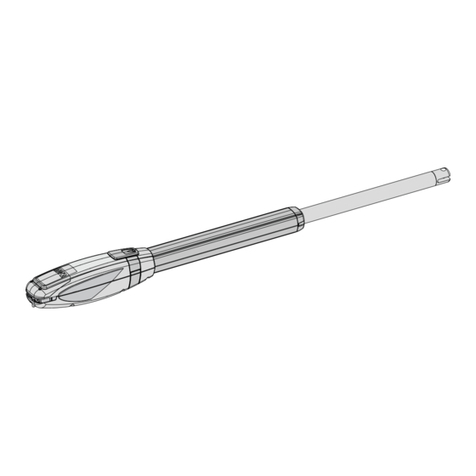
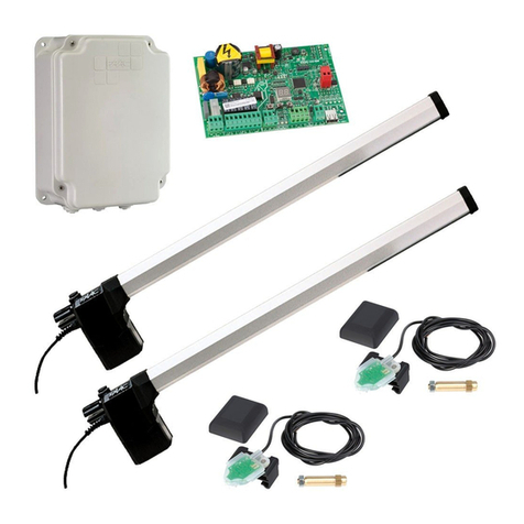
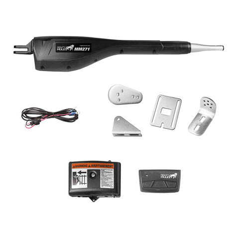
tau Stargate User manual

STARGATE
ITALIANPATENTAPPLICATIONN°VI97A000102ITALIANPATENTAPPLICATIONN°VI97A000102
EUROPEAN PATENTN°98111575.1EUROPEAN PATENTN°98111575.1
ISTRUZIONIDIMONTAGGIOISTRUZIONIDIMONTAGGIO
MONTAGEANWEISUNGENMONTAGEANWEISUNGEN
ASSEMBLYINSTRUCTIONSASSEMBLYINSTRUCTIONS
INSTRUCTIONS DE MONTAGEINSTRUCTIONS DE MONTAGE
INSTRUCCIONESPARA ELMONTAJEINSTRUCCIONESPARA ELMONTAJE
EDIZIONE 01-1999

I
D
GB
F
E
La Casa costruttrice si riserva il diritto di apportare modifiche o miglioramenti al prodotto senza alcun preavviso.
Eventuali imprecisioni o errori riscontrabili nella presente edizione, saranno corretti nella prossima edizione.
All’aperturadell’imballo verificare che ilprodotto sia integro.
Riciclare i materiali secondo la normativa vigente.
DieHerstellerfirmabehältsichdasRechtvor,ÄnderungenoderVerbesserungendesProduktesohneirgendeineVorankündigungvorzunehmen.
Eventuelle in diesem Handbuch feststellbare Ungenauigkeiten oder Fehler werden in der nächsten Ausgabe berichtigt werden.
Überprüfen Sie beim Öffnen der Verpackung, ob das Produkt unversehrt ist.
Recyclen Sie das Material gemäß der gültigen Vorschriften.
The manufacturer reserves the right to modify or improve them without prior notice.
Any inaccuracies or errors found in this manual will be corrected in the next edition.
Whenopeningthe packing please check that theproductis in excellent condition.
Pleaserecycle materials in compliancewith current regulations.
Le Constructeur se réserve le droit d’apporter des modifications ou des améliorations au produit sans aucun préavis.
Les éventuelles imprécisions ou erreurs trouvées dans cette édition seront corrigées dans la prochaine édition.
A l’ouverture de l’emballage, vérifier que le produit est intact.
Recyclerles matériaux selon laréglementation en vigueur.
Laempresa fabricante se reservael derecho a aportar modificaciones o mejorasen el producto sin aviso previo.
Posibles errores o imprecisiones que se detecten en este manual se corregirán en el próximo.
Cuandoabrael embalaje, compruebelaintegridaddelproducto.
Reciclar los materiales según las normativas vigentes
pag3pag3
pag4pag4
pag5pag5
pag6pag6
pag7pag7
pag8pag8
pag9pag9
pag10pag10
PAG12PAG12
CARATTERISTICHE TECNICHE, TECHNISCHE EIGENSCHAFTEN, TECHNICAL FEATURES, CARACTERISTIQUES TECHNIQUES,
CARACTERISTICAS TECNICAS.
SU CHE TIPO DI ANTA, AN WELCHEM TURTYP, ON WHAT TYPE OF GATE, SUR QUEL TYPE DE BATTANT, SOBRE QUE TIPO DE VERIA.
Fig, Abb.
MISURE PER L’INSTALLAZIONE, MAß FÜR INSTALLATION, DIMENSIONS FOR INSTALLATION, MESURES POUR INSTALLATION,
DIMENCIONES PARA LA INSTALACION. Fig, Abb.
MATERIALI PER L’INSTALLAZIONE, INSTALLATIONS MATERIALEN, TOOLS REQUIRED, OUTILS REQUIS, HERRAMIENTAS NECESARIAS.
Fig, Abb.
OPERAZIONI PRELIMINARI, EINLEITENDE EMPFEHJUNGEN, PRIOR CONSIDERATIONS, CONSIDERATIONS PRELIMINAIRES, CONSIDERACIONES
PRELIMINARES.
MONTAGGIO, MONTAGE, ASSEMBLY SECTION, PROCESSUS DE MONTAGE, SECCION DE MONTAJE.
FISSAGGIO DEL PROFILO E DELLA STAFFA, BEFESTIGUNG DES FÜHRUNGSPROFILS UND BÜGELS, SECURING THE TRACK SECTION AND
BRACKET, FIXATION DU GUIDE PROFIL ET PATTE, FIJACION DEL PERFIL DE GUIA J DE LA MORDAZA. Fig, Abb.
INSTALLAZIONE DEL MOTORIDUTTORE, INSTALLATION DER GETRIEBEMOTOR, ANCHORING THE MOTORGEAR INSTALLATION DE
MOTOREDUCTEUR, INSTALACION DEL MOTOREDUCTOR. Fig, Abb.
FISSAGGIO DEL TUBO, BEFESTIGUNG DER ARM, FIXING THE ARM, FIXATION DE LE BRAS, FIJACION DE EL BRAZO. Fig, Abb.
ALTRE OPERAZIONI, WEITERE ARBEITEN, OTHER OPERATIONS, AUTRES OPÉRATIONS, OTRAS OPERACIONES. Fig, Abb.
FISSAGGIO DELLA CENTRALINA, BEFESTIGUNG DER STEUERZENTRALE, FIXING THE CONTROL UNIT, FIXATION DE LA CEN-
TRALE, FIJACION DE LA CENTRALITA. Fig, Abb.
SBLOCCO MANUALE, VERWENDUNG DER MANUELLEN ENTRIEGELUNG, USE OF THE MANUAL UNLOCK, UTILISATION DU DEBLOCAGE
MANUEL, USO DEL DESBLOQUEO MANUAL. Fig, Abb.
ULTIME OPERAZIONI, LETZTE ARBEITEN, LAST OPERATIONS, DERNIÈRES OPÉRATIONS, ÚLTIMAS OPERACIONES. Fig, Abb.
LISTA RICAMBI, ERSATZTEILE, LIST OF SPARE PARTS, LISTE DES PIÈCES DE RECHANGE, LISTA DE RECAMBIOS. Fig, Abb.
USO, GEBRAUCH, USE, MODE D’EMPLOI, USO.
MANUTENZIONE, WARTUNG, MAINTENANCE, MAINTENANCE, MANTENIMIENTO.
RACCOMANDAZIONI GENERALI, ALLGEMEINE EMPFEHLUNGEN, GENERAL ADVICE, RECOMMANDATIONS DE CARACTERE GENERAL,
RECOMENDACIONES DE CARÁCTER GENERAL.
CENTRALINA MCP433, FUNKSTEUERZENTRALE MCP433, CENTRAL UNIT MCP433, CENTRALE MCP433, CENTRAL MCP433.
Fig, Abb.
AVETE BISOGNO DI ALTRI PRODOTTI ?...ECCO LA SOLUZIONE!, BRAUCHEN SIE NOCH ANDERE PRODUKTE ? . HIER IST DIE LÖSUNG!, DO
YOU NEED SOMETHING ELSE?...THAT’S SOLUTION!,
VOUS AVEZ BESOIN D’AUTRES PRODUITS?... VOICI LA SOLUTION!
NECESITA OTROS PRODUCTOS? ... ¡ESTA ES LA SOLUCIÓN!
1 2 3 4 5 6
7 8
9
11 19
20 22 23
24 25
26 30
22
31
32
35 36 37
pag.2
INDICEINDICE
VERZEICHNISVERZEICHNIS
CONTENTSCONTENTS
INDEXINDEX
INDICEINDICE

12Vdc
3200 giri/min ± 7%
70Kg
4.2W
0.35A
-20°C +60°C
1/16
1m
70Kg
1,9 Kg
ALIMENTAZIONE - STROMSPEISUNG - POWER - ALIMENTATION -ALIMENTACIÓN
MOTORE-MOTOR -ELECTRICAL MOTOR - MOTEUR - MOTOR
VELOCITA MOTORE (a vuoto) -MOTORGESCHWINDIGKEIT - MOTOR SPEED
VITESSE MOTEUR - VELOCIDAD MOTOR
SPINTA ASSIALE -LÄNGSSCHUB - AXIAL THRUST -POUSSÈE AXIALE - EMPUJE AXIAL
POTENZA NOMINALE RESA -AUFGENOMMENENENNLEISTUNG- ABSORBED RATED
OUTPUT -PUISSANCEABSORBÉE-POTENCIANOMINALABSORBIDA
CORRENTE NOMINALE -AUFGENOMMENER NENNSTROM- ABSORBED RATEDCURRENT
CUORANT ABSORBÉ - CORRIENTE NOMINAL
TEMPERATURA DI ESERCIZIO -BETRIEBSTEMPERATUR-OPERATINGTEMPERATURE
TEMPÉRATUREDEFONCTIONNEMENT-TEMPÉRATUREDEFONCTIONNEMENT
RAPPORTO DI RIDUZIONE - ÜBERSETZUNGSVERHÄLTNIS - REDUCTION RATIO-RAPPORT
DE RÉDUCTION - RELACIÓN DE REDUCCIÓN
LUNGHEZZA MAX ANTA- MAX FLÜGELLÄNGE - MAX GATELENGTH-LONGEURMAX
BATTANT - LONGITUD MÀX HOJA PUERTA
PESO MAX ANTA -MAXIMALE GEWICHT DES FLÜGEL- MAX GATE WEIGHT - POIDS MAX
BATTANT - PESO MÀX HOJA PUERTA
PESO MOTORIDUTTORE -GEWICHT - WEIGHT - POIDS - PESO
12Vcc
I-CARATTERISTICHE TECNICHE-CARATTERISTICHE TECNICHE D-TECHNISCHEEIGENSCHAFTEN-TECHNISCHEEIGENSCHAFTEN GB-TECHNICALFEATURES-TECHNICALFEATURES
F-CARACTERISTIQUESTECHNIQUES-CARACTERISTIQUESTECHNIQUES E-CARACTERISTICASTECNICAS-CARACTERISTICASTECNICAS
I
D
GB
F
E
Perla installazione rispettare lemisure riportatenellatabella a fianco erelative
alle fig.7 e 8. Per altre misure adottare altri tipi di automazione come riportato
allafinediquestomanuale.
Fürdie Installation die Maßein dernebenstehendenTabelle einhalten, die sichauf
dieAbb.++und++beziehen. FürandereMaße sindandere Automatisierungen
anzuwenden, wie am Ende dieser Anleitung angegeben.
To install, please observe the measurements given in the table by the side and
relativetoFigs.7 and8.For othermeasurementsuse othertypesof automationsas
shownat the end ofthis manual.
Pourl’installation, respecter lesmesuresdonnéesdansletableau ci-contre et
relatives aux figures 7 ou 8. En cas de mesures différentes, adopter d’autres
types d’automatisation suivant les indications figurant à la fin de ce manuel.
Para la instalación, respete las medidas indicadas en la tabla de al lado y referidas
alas figs. 7 y8. Para otras medidas,adopte otros tipos deautomatización,como
indicadoalfinaldeestemanual.
ANTAANTA
TORETORE
GATEGATE
PORTAILPORTAIL
VERIAVERIA
A (mm)A (mm) B (mm)B (mm)
80x80
90x90
100x100
120x120
150x150
160x160
155
85
90
110
140
150
150/180
140
145
155
150
135
200
200
185
165
150
MAX
1mx70Kg
90°
D(mm)D (mm) G (mm)G (mm) X°X°
FORON°FORON°
LOCH N°LOCH N°
HOLE N°HOLE N°
TROUN°TROUN°
FORON°FORON°
1
1
1
1
2
3
1 2
I-SUCHE TIPO DIANTA-SUCHE TIPO DIANTA D-AN WELCHEM TURTYP-AN WELCHEM TURTYP GB -ON WHAT TYPE OF GATE-ON WHAT TYPE OF GATE F-SURQUELTYPEDE-SURQUELTYPE DE
BATTANTBATTANT E-SOBREQUE TIPO DE VERIA-SOBREQUE TIPO DE VERIA
3
4 5
I
D
GB
F
E
Nelle figure indicate sono rappresentati i tipi di impianto che si possono automatizzare usando uno Stargate.
In den Abbildungen sind die Anlagentypen dargestellt, die mit Stargate automatisiert werden können.
The Figures show the types of plants that can be automated using one Stargate.
Les figures indiquées illustrent les types d’installation qui peuvent être automatisées en utilisant un dispositif Stargate.
Enlasfiguras indicadas están representados los tiposdeequipos que se pueden automatizar usandounStargate.
7 8
I-MATERIALI PER L’INSTALLAZIONEMATERIALI PER L’INSTALLAZIONE D-INSTALLATIONS-INSTALLATIONS GB-TOOLS REQUIRED-TOOLS REQUIRED F-OUTILSREQUIS-OUTILSREQUIS
E--HERRAMIENTHERRAMIENTASNECESARIASASNECESARIAS
IDGB FE
11
22
33
44
55
66
77
88
99
1010
1111
9
6
pag.3
I-MISUREPER L’INSTALLAZIONE-MISUREPER L’INSTALLAZIONE D-MAß FÜR INSTALLATION-MAß FÜR INSTALLATION GB-DIMENSIONSFORINSTALLATION-DIMENSIONSFORINSTALLATION
F-MESURESPOURINSTALLATION-MESURESPOURINSTALLATION E-DIMENCIONESPARALAINSTALACION-DIMENCIONESPARALAINSTALACION
motoriduttore
profilo PS attacco
motoriduttore
tubo
tappo
tappo
dadoautobloccanteM6/8
vite TCEI M8x35
ViteTCEI M6x20
Getriebemotor
Verankerungsplatte
Getriebemotor
arm
pfropfen
pfropfen
Selbstsichernde Mutter
VerzinktSchraube
VerzinktSchraube
Entriegelungsschlüssel
viteautoperforante
staffaattaccobraccio
chiave di sblocco
Anschlussbügel fur arm
Selbstsichernde Schraube
gearmotor
PS section gearmotor
connection
arm
cap
cap
self-locking hexagon nut
screw TCEI
screw TCEI
unlock key
armbracket
self-perforatingscrew
Motoréducteur
Plaque d’ancrage
motoréducteur
bras
bouchon
bouchon
crou E autobloquant
vis TCEI
vis TCEI
clè pour deblocage
patte de fixation bras
vis autoperforateur
Motoreductor
Placha de anclaje
motoreductor
brazo
tapòn
tapòn
tuerca E de seguridad
tornillos
tornillos
llave de desbloqueo
abrazadera de unión brazo
tornillos autoperforadores

FASI,ABSCHNITT,PHASES,PHASES,OPERACIONESFASI,ABSCHNITT,PHASES,PHASES,OPERACIONES
I
--MONTMONTAAGGIOGGIO D--MONTMONTAAGEGE GB-ASSEMBLYSECTIONASSEMBLYSECTION F-PROCESSUSDEMONTAGEPROCESSUSDEMONTAGE
E
-SECCIONDEMONTAJESECCIONDEMONTAJE
-OPERAZIONI PRELIMINARI
-OPERAZIONI PRELIMINARI
D-EINLEITENDEEMPFEHJUNGEN-EINLEITENDEEMPFEHJUNGEN GB-PRIORCONSIDERATIONS-PRIORCONSIDERATIONS
F
-CONSIDERATIONSPRELIMINAIRES-CONSIDERATIONSPRELIMINAIRES E-CONSIDERACIONESPRELIMINARES-CONSIDERACIONESPRELIMINARES
I
DD
GBGB
FF
EE
Leggere con attenzione le poche istruzioni presenti all’interno del manuale prima di iniziare qualsiasi operazione.
Prima di procedere alla installazione controllare che ci siano tutti i componenti, dotarsi degli strumenti idonei per lavorare e non maneggiare
su parti elettriche che siano alimentate. Successivamente inserire la spina della centralina nella presa della corrente, con il telecomando
azionare il motoriduttore, fargli compiere alcune manovre ed infine posizionarlo come indicato in fig 20; ora si può iniziare l’ installazione.
Vor Beginn von Arbeiten die wenigen, in der Anleitung enthaltenen Anweisungen aufmerksam lesen. Vor der Installation prüfen, ob alle Bestandteile
vorhanden sind, und sich mit für die Arbeit geeigneten Geräten ausstatten; keine unter Spannung stehenden elektrischen Teile handhaben. Dann den
Steckerder Zentrale indie Steckdose stecken,den Getriebemotor mitder Fernsteuerung betätigen und ein paar Bewegungen durchführen, dann wie
inAbb.20gezeigtpositionieren.NunkannmandieInstallationbeginnen.
Read the few instructions given inside the manual carefully before starting any work. Before actually starting to install, check you have all the
components, allthe suitable instruments needed; DONOT work on live parts.Now plug the control unitinto the mains and startthe gearmotor with the
remote control. Make it perform several manoeuvres and then position it as shown in Fig. 20. Now you can start installation.
Lire attentivement les instructions présentes dans le manuel avant toute opération. Avant de procéder à l’installation, contrôler que tous les
composants sont présents, se procurer des outils appropriés et éviter toute intervention sur des parties électriques quand elles sont alimentées.
Introduireensuite la fichede la centrale dans la prise de courant puis avec la télécommande, actionner le motoréducteur, lui faire accomplir quelques
manœuvres et le positionner comme l’indique la figure 20; il est alors possible de commencer l’installation.
Lea atentamente las pocas instrucciones que se encuentran en el interior del manual, antes de comenzar con los trabajos. Antes de empezar la
instalación, controle que estén todos los componentes, use los instrumentos idóneos para trabajar y no toque las piezas eléctricas que estén bajo
tensión. Luego,conecte el enchufe dela central en el tomacorriente; con el control remoto accione elmotorreductor, hágale cumplir algunasmaniobras
y,por último, colóquelo comoindicado en la fig.20; ahora puede empezarla instalación.
I
-FISSAGGIODELPROFILOEDELLASTAFFA-FISSAGGIODELPROFILOEDELLASTAFFA D-BEFESTIGUNGDESFÜHRUNGSPROFILSUNDBÜGELS-BEFESTIGUNGDESFÜHRUNGSPROFILSUNDBÜGELS
GB
-SECURINGTHETRACKSECTION AND BRACKET-SECURINGTHETRACKSECTION AND BRACKET F-FIXATIONDUGUIDEPROFILETPATTE-FIXATIONDUGUIDEPROFILETPATTE
E
-FIJACIONDEL PERFIL DE GUIA J DE LAMORDAZA-FIJACIONDEL PERFIL DE GUIA J DE LAMORDAZA
I
D
GB
F
Di seguito sono descritte le operazioni da eseguire per il fissaggio del profilo in alluminio e della staffa:
1-segnare sul pilastro e sull’anta del cancello la posizione dove praticare i fori rispettando l’allineamento come indicato nella fig.11,
utilizzando le misure riportate a pag.3 di questo manuale ed al limite servendosi della staffa per tracciare i fori;
2-praticare 3 fori sul pilastro utilizzando una punta da 6 se ho una struttura in metallo o da 8 se ho una struttura in muratura;
3-usando ora una punta da 6 praticare 2 fori sull’anta in corrispondenza delle posizioni prima segnate;
4-posizionare il profilo come indicato in fig.15 sull’anta assicurandosi che sia il più orizzontale possibile;
5-fissare il profilo all’anta usando le 2 viti autoperforanti in dotazione;
6-fissare la staffa al pilastro come indicato nelle fig.17 e 18 usando dei tasselli ad espansione in caso di struttura in muratura oppure delle viti
autoperforanti in caso di struttura metallica;
7-serrare le viti agendo con una chiave da 10 o con apposita bussola e cricchetto;
Hier folgend sind die Arbeiten für die Befestigung des Aluprofils und des Bügels beschrieben:
1-amPfeiler und am Torflügel die Stelle markieren, wo die Löcher gebohrt werden sollen, dabei die Fluchtung wie in Abb. 11gezeigt einhalten und die auf
Seite3dieserAnleitung angegebenen Maße benützenundsichimBedarfsfalldes Bügels bedienen, umdieLöcherwieinAbb.11 gezeigt zu markieren;
2-3 Löcher in den Pfeiler bohren; falls die Struktur aus Metall ist, einen Bohrer 6 verwenden, falls sie aus Mauerwerk ist, einen Bohrer 8 verwenden;
3-nun einen Bohrer 6 verwenden und 2 Löcher in den Torflügel an den vorher markierten Stellen bohren;
4-das Profil wie in Abb. 15 am Torflügel anbringen und sicherstellen, dass es so horizontal wie möglich ist;
5-das Profil mit den 2 mitgelieferten, selbstschneidenden Schrauben am Torflügel befestigen;
6-denBügel wie in den Abb.17 und 18 gezeigt amPfeiler befestigen, dabei im Falle von Mauerstruktur Spreizdübel verwenden, oderselbstschneidende
Schrauben im Fall von Metallstruktur;
7-die Schrauben mit einem Schlüssel 10 oder einer Gelenkhülse anziehen;
The operations to fix the aluminium section and bracket are described below:
1-Mark where the hole has to be made on the post and gate, keeping them aligned as indicatedin Fig. 11 and using the measurements given on
page 3 in this manual. If necessary use the bracket to mark the holes;
2 -Drill 3 holes on the post with a size 6 bit if it is metal or a size 8 bit if it is brick.
3 -With a size 6 bit, drill 2 holes on the gate where it has been marked.
4 -Position the section as indicated in Fig. 15 on the gate making sure it is as horizontal as possible.
5 -Fix the section to the gate with the 2 self-tapping screws provided.
6 -Fix the bracket to the post as shown in Figs. 17 and 18 using either expansion bolts on brick or self-tapping screws on metal.
7 -Tighten the screws with a size 10 spanner or box wrench.
Nousdécrivons ci-après lesopérations à exécuterpour la fixationdu profil en aluminium et de la patte de fixation.
1-Marquer sur le pilier ou sur le battant du portail l’emplacement des trous en respectant l’alignement comme l’indique la fig. 11, en respectant les
mesures figurant à la page 3 de ce manuel et en utilisant le cas échéant la patte pour marquer les trous;
2-Percer3trous sur lepilieravecunforet de 6 mmsi lastructureestmétalliqueou de 8 mmsi lastructureestenmaçonnerie.
3-Avec un foret de 6 mm, percer 2 trous sur le battant du portail, aux emplacements marqués au point 1.
4-Positionner le profil comme l’indique la figure 15 sur la porte en contrôlant qu’il soit le plus horizontal possible.
5-Fixer le profil au battant en utilisant les 2 vis autotaraudeuses fournies.
6-Fixer la patte au pilier comme l’indiquent les fig. 17 et 18 en utilisant des vis tamponnées en cas de structure en maçonnerie ou des vis
autotaraudeuses en cas de structure métallique.
7-Serrer les vis en utilisant une clé de 10 mmou avec un cliquet à douille.
11 31
11 19
pag.4
20

I-INSTALLAZIONEDEL MOTORIDUTTOREINSTALLAZIONEDEL MOTORIDUTTORE D-INSTALLATION DERGETRIEBEMOTOR-INSTALLATIONDERGETRIEBEMOTOR GB-ANCHORINGTHE-ANCHORINGTHE
MOTORGEARMOTORGEAR F-INSTALLATIONDEMOTOREDUCTEUR-INSTALLATIONDEMOTOREDUCTEUR E-INSTALACIONDELMOTOREDUCTOR-INSTALACIONDELMOTOREDUCTOR 20 22
I
D
GB
F
E
I-FISSAGGIODEL TUBOFISSAGGIODEL TUBO D-BEFESTIGUNG DER ARM-BEFESTIGUNG DER ARM GB-FIXINGTHEARM-FIXINGTHEARM F-FIXATION DE LE BRAS-FIXATION DE LE BRAS
E-FIJACIONDEELBRAZO-FIJACIONDEELBRAZO
I
D
GB
F
E
23
NB: le seguenti operazioni sono da compiersi ad anta chiusa.
1-Collocare il tubo come indicato in fig.23 in modo che agganci sul foro della chiocciola e quello della staffa;
2-Fissare il tubo alla chiocciola con l’apposita vite e dado come indicato nel particolare B, per bloccare la vite servirsi della chiave in dotazione e di
unapinzaper stringere il dado;
3-Fissare il tubo alla staffa con l’apposita vite e dado come indicato nel particolare A, per bloccare la vite servirsi della chiave in dotazione e di
unapinzaper stringere il dado;
Per sapere quale dei 3 fori della staffa si deve usare, consultare la tabella riportante le misure di installazione.
NB: Folgende Arbeiten müssen mit geschlossenem Torflügel ausgeführt werden
1-DasRohrwie in Abb. 23 anordnen, sodasses sich am Loch des Spiralgehäusesundan jenem des Bügels einhängt;
2-Das Rohr wie in Detail B gezeigt mit der Schraube und Mutter am Spiralgehäuse befestigen; zum Blockieren der Schraube den mitgelieferten
Schlüsselverwenden, zum Anziehen der Mutter eine Zange benützen.
3-Das Rohr wie in Detail A gezeigt mit der Schraube und Mutter am Bügel befestigen; zum Blockieren der Schraube den mitgelieferten Schlüssel
verwenden,zum Anziehen der Mutter eineZangebenützen;
Umzuwissen,welches der 3 Bügellöcher benützt werden soll, dieTabellemitden Installationsmaßen zur Hand nehmen.
N.B.: the following operations are to be done with the gate closed.
1-Place the pipe as shown in Fig. 23 so it hooks on to the lead screw hole and bracket hole.
2-
Fixthe pipe to the lead screw using the screw andnut as shown in item B; to tighten the screwuse the spanner provided and a pair of pliers totighten the nut.
3-
FixthepipetothebracketusingthescrewandnutasshowninitemA;totightenthescrewusethespannerprovidedandapairofplierstotightenthenut.
To know which of the 3 bracket holes to use consult the table giving the installation measurements.
N.B. Les opérations qui suivent doivent être effectuées avec le battant fermé.
1-Placer le tube comme l’indique la fig. 23 de manière qu’il s’accroche sur le trou de la vis mère et sur celui de la patte.
2-Fixerletubeàlavismèreaveclavisetl’écroucommel’indiqueledétailB;pourbloquerlavis,utiliserlacléfournieetunepincepourserrerl’écrou.
3-Fixer le tube à la patte avec la vis et l’écrou comme l’indique le détail A; pour bloquer la vis, utiliser la clé fournie et une pince pour serrer l’écrou.
Pour savoir quel trou utiliser sur la patte, consulter le tableau avec les mesures d’installation.
N.B.: las siguientes operaciones se tienen que llevar a cabo con la hoja cerrada.
EA continuación se describen los trabajos que hay que efectuar para la sujeción del perfil de aluminio y del estribo:
1-marque sobre el pilar y sobre la puerta la posición en donde realizar los agujeros, respetando la alineación como indicado en la fig. 11, utilizando las
medidasindicadas enla pág.3 de este manual y,sifuera necesario, usando el estribo paramarcarlos agujeros;
2-realice 3 agujeros en el pilar utilizando una broca de 6 mm si la estructura es de metal, o de 8 mm si la estructura es de mampostería;
3-usandouna broca de 6 mm,realice 2 agujeros enla hoja en correspondencia de las posiciones antes marcadas;
4-coloque el perfil como indicado en la fig. 15 sobre la hoja, asegurándose de que quede lo más horizontal posible;
5-fije el perfil a la hoja, usando los 2 tornillos taladradores suministrados;
6-fije el estribo al pilar, como indicado en las figs. 17 y 18, usando los tornillos de expansión si la estructura es de mampostería, o los tornillos taladradores
si la estructura es de metal;
7-apriete los tornillos con una llave de 10 mm o con una llave allen y trinquete;
pag.5
1-Infilare il motoriduttore come indicato in fig.20 sul profilo fissato in precedenza in modo che il lato da cui fuoriesce il cavo del
motore sia rivolto verso il pilastro o i cardini dell’anta come indicato in fig.20 (in fig.21 è ingrandito il particolare del profilo di
aggancio in cui si trova la spina/perno per sblocco e blocco del motoriduttore).
2-Infilare la chiave, fornita di serie, sulla vite inserita nel coperchio del motore come illustrato in fig.22 e ruotare di circa 1/4 di giro al fine di ottenere
l’agganciosul perno;provareaspostaremanualmenteilmotoriduttoreperverificarechel’agganciosiaavvenuto.
NB: con la stessa chiave è possibile realizzare lo sblocco del motoriduttore nel caso in cui manchi la corrente.
1-DenGetriebemotor wie inAbb. ++ gezeigt auf das vorher befestigte Profil so einsetzen, dass die Seite, an der das Motorkabel herausgeht, zum
Pfeiler oder zu den Angelzapfen des Torflügels hin gerichtet ist, wie in Abb. 20 gezeigt (in Abb. 21 ist das Detail des Einhängprofils vergrößert, an
dem sich der Stift/Zapfen zum Entsperren und Blockieren des Getriebemotors befindet).
2-Denserienmäßiggelieferten Schlüssel wie in Abb. 22gezeigtauf die Schraube im Motordeckel steckenundum ca. ¼ Umdrehung drehen, so dass
das Einhängen am Zapfen verursacht wird; dann versuchen, den Getriebemotor von Hand zu verschieben, um zu prüfen, ob das Einhängen
erfolgreich war.
N.B.: mit dem gleichen Schlüssel kann der Getriebemotor bei Stromausfall entsperrt werden.
1-Insert the gearmotor as shown in Fig. 20 on the section you have just fixed, so the side where the cable is, faces the post or gate hinges as shown in
Fig. 20 (Fig. 21 shows an enlargement of the hooking section on which the pin is to release and lock the gearmotor).
2-Fit the spanner (standard accessory) on the screw on the motor’s cover as illustrated in Fig. 22 and turn it about 1/4 of a turn so the gearmotor hooks
ontothepin;try to move the gearmotorby hand to check ithasbeen securely hooked.
N.B. you can use the same spanner to release the gearmotor if there is a power cut.
1-Enfiler le motoréducteur comme l’indique la fig. 20 sur le profil fixé précédemment de manière que le côté d’où sort le câble soit tourné vers le pilier
ou les gonds du battant comme l’indique la fig. 20 (la fig. 21 illustre le détail agrandi du profil d’accrochage où se trouve la cheville/le pivot pour le
déblocageetleblocage du motoréducteur).
2-Enfiler la clé comprise dans la fourniture sur la vis insérée dans le couvercle du moteur comme l’illustre la fig. 22 et tourner d’environ ¼ de tour
pour obtenir l’accrochage sur le pivot; essayer de déplacer manuellement le motoréducteur pour vérifier si l’accrochage a eu lieu.
N.B.Avec la même clé.il est possible de débloquer le motoréducteuren cas de panne de courant.
1-Introduzca el motorreductor, como indicado en la fig. 20, en el perfil antes fijado, de manera que el lado por el cual sobresale el cable del motor esté
dirigido hacia el pilar o hacia los goznes de la hoja, como indicado en la fig. 20 (en la fig. 21 está ampliado el detalle del perfil de enganche en el cual
se encuentra el pasador/perno para desbloquear y bloquear el motorreductor).
2-Introduzca la llave suministrada de serie en el tornillo colocado en la tapa del motor, como muestra la fig. 22, y gire alrededor de 1/4 de vuelta para que
se enganche en el perno; trate de desplazar manualmente el motorreductor para comprobar que se haya enganchado.
N.B.: con la misma llave se puede desbloquear el motorreductor en el caso de que falte la corriente.

I
D
GB
F
E
NB: operazioni consigliate:
1-Proteggere i cavi con una guaina flessibile.
2-tagliareconunaforbiceunpezzodiguainaspiralatadella lunghezza minima di 40 cm;
3-infilare i cavi di uscita del motore nella guaina come indicato in fig.25;
4-lasciare la guaina abbastanza libera in prossimità dell’asse di rotazione dell’anta per evitare che si spezzi, attorcigli o si schiacci danneggiando i
cavi motore.
NB:empfohleneArbeiten:
1-DieKabelmiteinemflexiblenMantelschützen.
2-mit einer Schere ein mindestens 40 cm langes Stück Spiralmantel abschneiden;
3-dieAusgangskabeldesMotorswie in Abb. 25 gezeigt indenManteleinstecken;
4-den Mantel in der Nähe der Drehachse des Torflügels ziemlich frei lassen, damit er nicht zerbrechen, sich verwickeln oder sich zerquetschen
kann,wodurchdie Motorkabel beschädigtwürden.
NB:Werecommend:
1-Protect the cables with a flexible sheath.
2-cutting a piece of spiralled sheath, minimum 40 cm long, with a pair of scissors.
3-inserting the motor’s output cable in the sheath as shown in Fig. 25.
4-leaving the sheath quite free near the gate’s rotation axis so as to avoid it from breaking, getting twisted or crushed and damaging the motor cables.
NB: opérations conseillées:
1-Protéger les câbles avec une gaine flexible.
2-Couperavec unepairedeciseauxunboutde gainespiraléed’unelongueurminimumde40 cm.
3-Enfilerles câbles sortant du moteur dans la gaine comme l’indique la fig. 25.
4-Laisserla gainelibreàproximité del’axederotation dubattantpouréviterqu’ellesecasse, s’entortilleous’écraseen endommageantlescâblesdu moteur.
NB:operacionesaconsejadas:
1-Proteger los cables con una vaina flexible.
2-corteconunatijeraunpedazodevainaenespiralde 40 cm de longitud como mínimo;
3-introduzcalos cables de salida delmotoren la vaina, como indicadoen la fig. 25;
4-deje la vaina bastante libre en proximidad del eje de rotación de la hoja para que no se rompa, retuerce o aplaste, así averiando los cables del motor.
I
D
GB
24 25
26 30
1-Individuare la posizione più congeniale per posizionare la centralina
2-Ladistanza massima trala centralina ed il motore più lontano deve essere minore di 10 metri;
3-Segnare con una matita la posizione in cui andranno praticati i fori per l’inserimento dei tasselli o delle viti di fissaggio;
4-Praticare n°2 fori con una punta da 6 oppure da 8 a seconda che la struttura sia in metallo oppure in muratura;
5-Nel caso si struttura muraria infilare nei fori appena praticati 2 tasselli, quindi collocare la centralina e bloccarla alla parete con delle viti idonee;
6-Nel caso di struttura in metallo utilizzare 2 viti autoperforanti per fissare la centralina alla struttura;
7-Se si vuole: bloccare la guaina spiralata utilizzando delle apposite graffette prestando attenzione al fatto di lasciarla abbastanza libera in prossimità
dell’asse dell’anta.
Quindi:
8 - aprire il coperchio della scatola contenente la centralina;
9 - serrare il dado sottostante la scatola in modo che il cavo non sia libero di scorrere;
10-richiudereilcoperchiodellascatola.
NB: Invertendoicollegamenti,ilmotoreinverteilsensodirotazione.
1 - Die für die Zentrale geeignetste Stellung festlegen.
2 - Der Abstand zwischen Steuerzentrale und am weitesten entfernten Motor darf nicht großer als 10 Meter sein.
3 - Die Stelle, an der die Löcher zum Einfügen der Dübel und der Klemmschrauben gebohrt werden, mit einem Bleistift markieren;
4 - 2 Löcher bohren, dazu je nach Struktur (Metall oder Mauer) einen Bohrer 6 oder 8 verwenden;
5- Im Fall von Mauerstruktur 2 Dübel in die soebengebohrten Löcher stecken, dann die Zentrale anordnen und mit passenden Schrauben an der
Wand blockieren;
6 - Im Fall von Metallstruktur 2 selbstschneidende Schrauben zur Befestigung der Zentrale an der Struktur benützen;
7 - Will man den Spiralmantel mit Klammern blockieren, ist zu beachten, dass der Mantel in der Nähe der Torflügelachse ziemlich frei sein muss.
Dann:
8- den Deckel des Gehäuses öffnen, dasdie Zentrale enthält;
9 - die Mutter unter dem Gehäuse anziehen, damit das Kabel nicht frei gleiten kann;
10-denGehäusedeckel wieder schließen.
NB: Werden die Anschlüße vertauscht, so wird die Drehrichtung des Motors umgekehrt.
1 - Find the best position for the control unit.
2-Thedistancemaximumbetweenthecontrolunitandthefurthestmotor must be no more than 10 metres.
3 - With a pencil mark where the holes have to be made for the anchors or securing screws;
4 - Drill 2 holes with a size 6 or 8 bit, according to whether the structure is metal or brick;
5 - In the case of a brick structure, insert 2 anchor bolts in the holes you have just drilled, position the control unit, and secure it to the wall with suitable screws;
6 - In the case of a metal structure, use 2 self-tapping screws to secure the control unit to it;
7 - If you want you can secure the spiralled sheath with clips but you should leave it free by the gate’s axis.
Then:
8 - open the cover of the control unit box;
pag.6
-FISSAGGIODELLA CENTRALINA
-FISSAGGIODELLA CENTRALINA
D-BEFESTIGUNGDERSTEUERZENTRALE-BEFESTIGUNGDERSTEUERZENTRALE GB-FIXINGTHECONTROLUNIT-FIXINGTHECONTROL UNIT
F
-FIXATIONDELACENTRALE-FIXATIONDELACENTRALE E-FIJACION DE LA CENTRALITA-FIJACION DE LA CENTRALITA
-ALTRE OPERAZIONIALTRE OPERAZIONI D-WEITERE ARBEITEN-WEITERE ARBEITEN GB-OTHEROPERATIONS-OTHEROPERATIONS F-AUTRES OPÉRATIONS-AUTRES OPÉRATIONS E-OTRAS-OTRAS
OPERACIONESOPERACIONES
1-Coloque el tubo como indicado en la fig. 23, de manera que se enganche en el agujero de la tuerca del husillo y en el del estribo;
2-Fije el tubo a la tuerca del husillo con el tornillo y tuerca correspondiente, como indicado en el detalle B; para bloquear el tornillo use la llave suministrada
y una pinza para apretar la tuerca;
3-Fijeel tubo al estribo con el tornillo y tuerca correspondiente, comoindicado en el detalle A; para bloquearel tornillo use la llave suministrada yuna pinza
para apretar la tuerca;
Para saber cuál es el agujero del estribo que hay que usar, consulte la tabla en donde están las medidas de instalación.

I
D
GB
F
E
Ad installazione completata accertarsi che il foro inferiore del motoriduttore sia libero per consentire il defluire dell’acqua che
può normalmente entrare all’interno del guscio in alluminio.
NachderInstallationsicherstellen,obdasuntereLochamGetriebemotorfreiist,damitdas Wasser abfließen kann, das gewöhnlich in das Aluminiumgehäuse
eindringenkann.
Once installed, make sure the gearmotor’s bottom hole is free so that water can flow out that can quite easily get inside the aluminium case.
Quand l’installation est terminée, s’assurer que le trou inférieur du motoréducteur est libre pour permettre le drainage de l’eau qui pourrait pénétrer
danslecaisson en aluminium.
Cuandohayafinalizadolainstalación,asegúrese de que el agujero inferior del motorreductorquedelibreparapermitirquesalgaelaguaquepueda entrar
en el interior de la caja de aluminio.
I
D
GB
F
E
Qualora si verifichi un black-out le operazioni da compiere per consentire una apertura dell’anta sono le seguenti:
1-Infilare la chiave di bloccaggio fornita in dotazione nella testa a brugola della vite come illustrato in fig.22;
2-ruotarein senso orario o antiorario per circa1/4 di giro;
3-spostare manualmente il motore per verificare che esso sia libero di scorrere sul profilo di ancoraggio (part.2 di fig.10);
4-per il bloccaggio collocare l’anta in posizione di chiusura, ruotare la chiave di 1/4 di giro, assicurarsi che il bloccaggio sia sicuro quindi provare a
compiere unamanovra.
BeiStromausfallsindfolgendeArbeitsschrittezum Öffnen des Torflügels durchzuführen:
1-Den mitgelieferten Schlüssel zum Blockieren wie in Abb. 22 gezeigt in den Seckskantkopf der Schraube einstecken;
2-ca.1/4Umdrehungnach rechts oderlinksdrehen;
3-den Motor von Hand verschieben, um zu prüfen, ob er frei auf dem Ankerprofil gleiten kann (Detail 2, Abb. 10);
4-zumBlockierenden Torflügel in Schließung anordnen, denSchlüsselum ¼ Umdrehung drehen und prüfen,obdas Blockieren sicher ist, dann
versuchen, eine Bewegung auszuführen.
Inthecase of power cut, proceed asfollowsto open the gate:
1-Insertthe locking spanner, supplied, on the Allen screw, as illustrated in Fig. 22;
2-turn it either to the right or left about 1/4 of a turn;
3-move the motor manually to make sure it is free to slide on the securing section (item 2 of Fig. 10);
4-to lock, close the gate and turn the spanner 1/4 of a turn; check it is locked well and then try to carry out a manoeuvre.
En cas de panne de courant, les opérations à accomplir pour pouvoir ouvrir le battant sont les suivantes:
1-Enfiler la clé de blocage fournie dans la tête de la vis à 6 pans en creux, comme l’illustre la fig. 22.
2-Serrer dans le sens des aiguilles d’une montre ou dans le sens contraire d’environ ¼ de tour.
3-Déplacer manuellement le moteur pour vérifier s’il est libre de coulisser sur le profil d’ancrage (détail 2 de la fig. 10).
4-
Pour le blocage, placer le battant en position de fermeture, tourner la clé d’1/4 de tour, s’assurer que le blocage est sûr puis faire un essai de manœuvre.
Si se produjera un corte de energía, las operaciones que hay que efectuar para abrir la puerta son las siguientes:
1-introduzca la llave de bloqueo suministrada de serie en la cabeza del tornillo allen, como muestra la fig. 22;
2-gire hacia la derecha o izquierda 1/4 de vuelta aprox.
3-desplace manualmente el motor para comprobar que el mismo pueda correr libremente por el perfil de anclaje (detalle 2, fig. 10);
4-para el bloqueo, coloque la puerta en posición de cierre, gire la llave 1/4 de vuelta, asegúrese de que el bloqueo sea seguro, y trate a realizar una
maniobra.
F
E
9 - tighten the nut under the box to stop the cable moving;
10-closethecover.
NB: By reversing connections the motor should reverse rotating direction.
1 - Identifier l’emplacement le plus approprié pour positionner la centrale
2 - La distance maximum entre la centrale et le moteur le plus éloigné ne doit pas dépasser 10 mètres.
3 - Marquer avec un crayon l’emplacement pour les trous dans lesquels seront placés les chevilles ou les vis.
4 - Percer 2 trous avec un foret de 6 mm si la structure est en métal ou de 8 mm si la structure est en maçonnerie.
5 - Si la structure est en maçonnerie, enfiler dans les trous 2 chevilles puis placer la centrale et la fixer au mur avec des vis adaptées.
6 - Si la structure est en métal, utiliser 2 vis autotaraudeuses pour fixer la centrale à la structure.
7 - Le cas échéant, on peut bloquer la gaine spiralée avec des agrafes en veillant à la laisser suffisamment libre à proximité de l’axe du battant.
Puis:
8 - Ouvrir le couvercle du boîtier de la centrale.
9 - Serrer l’écrou situé sous le boîtier pour que le câble ne puisse pas coulisser.
10 -Refermer le couvercle du boîtier.
NB: Quand on invertit les connexions, le moteur invertit le sens de rotation.
1- Localice la posición más conveniente paracolocar la central.
2- La distanciamàxima entre lacentral y elmotor màs lejano no tiene que superar los 10 metros.
3- Marque conun lápiz la posición en la cual realizará los agujeros para introducir las espigas y los tornillos de sujeción;
4- Realice 2 agujeros con una broca de 6 mm si la estructura es de metal,o de 8 mm si la estructura es de mampostería;
5 - si la estructura es de mampostería, introduzca en los agujeros 2 espigas, coloque la central y bloquéela a la pared con los tornillos;
6 - si la estructura es de metal, use 2 tornillos taladradores para fijar la central a la estructura;
7 - si lo desea, bloquee la vaina en espiral con abrazaderas, teniendo cuidado de dejarla bastante libre en proximidad del eje de la hoja.
Luego,
8 - abra la tapa de la caja en la cual se encuentra la central;
9 - apriete la tuerca que está debajo de la caja, para que el cable no se pueda mover;
10-cierrede nuevo latapadelacaja.
NB: Invirtiendo las conexiones, el motor invierte el sentido de rotación.
22
31
pag.7
I-SBLOCCOMANUALE-SBLOCCOMANUALE D-VERWENDUNGDERMANUELLENENTRIEGELUNG-VERWENDUNGDERMANUELLENENTRIEGELUNG GB-USEOFTHEMANUALUNLOCK-USEOFTHEMANUALUNLOCK
F-UTILISATIONDUDEBLOCAGEMANUEL-UTILISATIONDUDEBLOCAGEMANUEL E-USO DELDESBLOQUEOMANUAL-USODELDESBLOQUEO MANUAL
I-ULTIME OPERAZIONI-ULTIME OPERAZIONI D-LETZTE ARBEITEN-LETZTEARBEITEN GB-LAST OPERATIONS-LAST OPERATIONS F-DERNIÈRESOPÉRATIONS-DERNIÈRESOPÉRATIONS
E-ÚLTIMASOPERACIONES-ÚLTIMASOPERACIONES

1-motore12Vdc
2-rondella
3-anello seeger
4-piastrina
5-vite
6-sedecuscinetto
7-cuscinetto
8-vitesenza-fine
9-chiocciola
10-spina elastica
11-profilosede-motore
12-vite
13-linguettacorta
14-tapochiuso
15-piastrina
16-vite
17-distanziale
18-eccentrico
19-granoapunta
20-vite
21-linguettalunga
22-tappomotore
23-vite
24-pressacavo
25-tappo
1-Motor12Vdc
2-Unterlegscheibe
3-Seegerring
4-KleinePlatte
5-Schraube
6-Lagersitz
7-Lager
8-Schnecke
9-Mutter
10-Spannstift
11-Motorsitz-Profil
12-Schraube
13-kurzer Federkeil
14-geschlossenerStopfen
15-Kleine Platte
16-Schraube
17-Distanzstück
18-Nocken
19-spitzer Stift
20-Schraube
21-langerFederkeil
22-Motorverschluss
23-Schraube
24-Kabelhalterl
25-Stopfen
1-12Vdcmotor
2-washer
3-snap-ring
4-plate
5-screw
6-bearinghousing
7-bearing
8-wormscrew
9-leadscrew
10-pistonring
11-housing-motorsection
12-screw
13-shorttab
14-closedcap
15-plate
16-screw
17-spacer
18-eccentric
19-pointeddowel
20-screw
21-long tab
22-motorcap
23-screw
24-grommet
25-cap
IDGB FE
1-moteur12Vcc
2-rondelle
3-bagueseeger
4-plaquette
5-vis
6-logementroulement
7-roulement
8-vis sans fin
9-vismère
10-chevilleélastique
11-profil logement moteur
12-vis
13-languettecourte
14-bouchonfermé
15-plaquette
16-vis
17-entretoise
18-excentrique
19-goujon en pointe
20-vis
21-anguettelongue
22-bouchonmoteur
23-vis
24-presseétoupe
25-bouchon
1-motor12Vdc
2-arandela
3-arandela seeger
4-placa
5-tornillo
6-asiento del cojinete
7-cojinete
8-tornillo sin fin
9-tuerca del usillo
10-pasadorelàstico
11-perfilalojamientomotor
12-tornillo
13-lenguetacorta
14-tapóncerrado
15-placa
16-tornillo
17-espaciador
18-excéntrica
19-pasadordepunta
20-tornillo
21-lenguetalarga
22-tapón del motor
23-tornillo
24-sujetacable
25-tapón/etiqueta
32
I
D
GB
Si fa espresso divieto di utilizzare l’apparecchio per scopi diversi o in circostanze diverse da quelle menzionate.
Si ricorda che siamo in presenza di un dispositivo automatico e alimentato a corrente, perciò da usare con precauzione. In particolare,
si ammonisce di:
- non toccare l’apparecchio con mani bagnate e/o piedi bagnati o nudi;
- togliere la corrente prima di aprire la scatola comandi e/o il motoriduttore;
-mettere in movimento il cancello solo quandoè completamente visibile;
- tenersi fuori dal raggio di azione del cancello se questo è in movimento: aspettare fino a che non sia fermo;
- non lasciare che bambini o animali giochino in prossimità del cancello;
- non lasciare che bambini o persone incapaci usino il telecomando o dispositivi di azionamento;
- effettuare una periodica manutenzione;
- in caso di guasto, togliere l’alimentazione e gestire il cancello manualmente solo se possibile ed in condizioni di sicurezza.
Astenersi da ogni intervento e chiamare un tecnico specializzato.
Eswird ausdrücklich verboten, dieVorrichtung für unterschiedliche Zweckeoder unter Umständen einzusetzen,die von
den genannten abweichen.
Es wird daran erinnert, daß es sich um eine automatische Vorrichtung handelt, die mit Strom gespeist wird und daher mit
Vorsicht zu verwenden ist. Im besonderen wird vor folgendem gewarnt:
-dieVorrichtung nicht mit feuchten Händen und/oderfeuchtenoder nackten Füßen berühren;
- die Stromzufuhr unterbrechen, bevor das Steuergehäuse und/oder der Getriebemotor geöffnet werden;
- das Gittertor nur in Bewegung setzen, wenn es vollständig sichtbar ist;
- sich außerhalb des Aktionsradius des Gittertores aufhalten, wenn sich dieses in Bewegung befindet;
- Kinder oder Tiere nicht in der Nähe des Gittertores spielen lassen;
- Kinder oder unfähige Personen nicht die Fernsteuerung oder andere Vorrichtungen für die Betätigung verwenden lassen;
- eine periodische Wartung durchführen;
- im Falle einer Störung die Stromzufuhr unterbrechen und das Gittertor nur dann manuell betätigen, wenn dies möglich und sicher ist.
Keine Eingriffe durchführen und einen autorisierten Techniker rufen.
It is absolutely forbidden to use the device for any other purposes or under circumstances different from those mentioned.
It could appen that there is not electricity, in this case you can operate the gate manually but first you have to “unlock” it. Remember
thatthisisan automatic device which is powered by electricity,consequentlyusewith care. In particular, remember:
- do not touch it with wet hands and/or wet or bare feet
- turn the electricity off before opening the control box and/or geared motor
- only operate the door when it is completely visible
- keep out of the door’s range of action if it is moving: wait until it has stopped
- do not let children or animals play near the door
- do not let children, or incapable people, use the remote control or other operating devices
- carry out routine maintenance
- in the case of a failure, turn the electricity off and work the door manually only if it is possible and safe to do so.
Refrain from touching the door and callan authorised technician.
pag.8
I-
USOUSO D-GEBRAUCH-GEBRAUCH GB --USEUSE F-MODED’EMPLOI-MODED’EMPLOI E-USO-USO
LISTARICAMBILISTARICAMBI
ERSATZTEILEERSATZTEILE
LIST OF SPARE PARTSLIST OF SPARE PARTS
LISTEDES PIÈCES DE RECHANGELISTEDES PIÈCES DE RECHANGE
LISTADE RECAMBIOSLISTADERECAMBIOS

F
E
Il est absolument interdit d’utiliser l’appareil pour des usages différents ou dans des circonstances différentes de celles qui sont
mentionnées dans ce livret. Nous rappelons que nous sommes en présence d’un dispositif automatique alimenté par le courant électrique; il faut
donc prendre toutes les précautions de rigueur.
Enparticulier,faire attention à:
- ne pas toucher l’appareil avec les mains mouillées et/ou avec les pieds mouillés ou nus;
- couper le courant avant d’ouvrir le boîtier des commandes et/ou le motoréducteur;
- ne pas tirer le cordon d’alimentation pour débrancher la prise de courant;
- mettre en mouvement le portail seulement quand il est complètement visible;
- rester hors du rayon d’action du portail tant qu’il est en mouvement: attendre qu’il soit complètement arrêté;
-nepaslaisserles enfants ou les animaux jouer à proximitéduportail;
-nepaslaisserdesenfantsoudesincapablesmanipulerlatélécommandeoud’autresdispositifsd’actionnement;
- effectuer la maintenance périodique;
- en cas de panne, couper l’alimentation, ouvrir et fermer manuellement le portail seulement si cette opération est possible et sûre.
Eviter toute intervention et faire appel à un technicien agréé.
Se recuerda explícitamente que está prohibido usar el aparato para fines diversos o en circunstancias diferentes de las
mencionadas. Se recuerda que nos hallamos ante un dispositivo automático alimentado por corriente eléctrica, por lo tanto, debe usarse con
precaución.
En particular se recomienda:
- No tocar el aparato con la manos mojadas y/o con los pies mojados o descalzos;
- Desconectar la corriente antes de abrir la caja de mandos y/o el accionador;
-Notirardel cable de alimentaciónparadesconectarlatomadelacorriente;
-Moverla verja sólo cuando sea completamentevisible;
- Mantenerse fuera del radio de acción de la verja, si ésta se halla en movimiento, esperar hasta que se haya detenido;
- No dejar que niños o animales jueguen cerca de la verja;
- No dejar que niños o personas incapacitadas usen el mando a distancia u otros dispositivos de accionamiento;
-Realizarun mantenimiento periódico.
I
D
GB
F
E
1-In accordo con la normativa europea in materia di sicurezza si consiglia di inserire un interruttore esterno per poter togliere l’alimenta-zione
incasodi manutenzione del cancello.
2-Verificare che ogni singolo dispositivo installato sia efficiente ed efficace.
3-Affiggerecartelli facilmente leggibili che informino della presenzadel cancello motorizzato.
1-InÜbereinstimmung mit den europäischenSicherheitsvnormen wird die Installationeines externen Schalters empfohlen,um die
Stromzufuhr bei einer Wartung des Gittertores unterbrechen zu können.
2-Überprüfen, ob jede einzelne installierte Vorrichtung leistungsfähig und wirksam ist.
3-Leichtlesbare Schilder anbringen, die darüberinformierendaß es es sich umein motorgetriebenes Tor handelt.
1-In compliance with European standards regarding safety, we recommend the installation of an outdoor switch for cutting off electricity
when the gate has to be serviced.
2-Check that each single device installed is efficient and effective.
3-Affix easily readable signs warning people that the gate is motor-driven.
1-Conformément à la norme européenne en matière de sécurité, il est conseillé d’insérer un interupteur externe pour pouvoir couper
l’alimentation en cas d’intervention de maintenance sur le portail.
2-Vérifier que tous les dispositifs installés fonctionnent correctement.
3-Placer des panonceaux bien lisibles qui informent de la présence du portail motorisé.
1-Paralapuesta a puntoapuntodelparmàximo motoreductor, respetarlanormativaenvigor.
2-De acuerdo con la normativa europea en materia de seguridad, se aconseja instalar un interruptor externo para poder sacar la corriente cuando
se deban realizar operaciones de mantenimiento de la verja. Comprobar que cada uno de los dispositivos funcione y sea eficaz.
3-Colocar carteles de fácil lectura y comprensión que informen de la presencia de una verja motorizada.
I
D
GB
F
E
Unavolta che è installatoin modo appropriato, Stargate darà una ottimaprestazione con un minimo di manutenzione.
Stargate non richiede ulteriore lubrificazione.
WennderStargate richtig eingebautist,bleibterbeiminimalem Aufwand fürdieInstandhaltungvollleistungsfähig.
Der Stargate erfordert keine zusätzliche Schmierung.
When properly installed, the Stargate system will provide high performance with a minimum of maintenance.
The Stargate system doesn’t require additional lubrication.
Quand le Stargate est installé correctement il fonctionne parfaitement avec un minimum d’entretien.
Il n’a pas besoin de lubrification supplémentaire.
Cuandose instalecorrectamenteelStargate,esteesteproporcionaràunexcelentefunciònamiento conunminimo demantenimiento.
El abridor no requiere de lubricaciòn adicional.
pag.9
I-MANUTENZIONE-MANUTENZIONE D-WARTUNG-WARTUNG GB -MAINTENANCE-MAINTENANCE F-MAINTENANCE-MAINTENANCE E-MANTENIMIENTO-MANTENIMIENTO
I--RACCOMANDAZIONI GENERALIRACCOMANDAZIONI GENERALI D-ALLGEMEINE EMPFEHLUNGEN-ALLGEMEINE EMPFEHLUNGEN GB --GENERALADVICEGENERALADVICE
F-RECOMMANDATIONSDECARACTEREGENERAL-RECOMMANDATIONSDECARACTEREGENERAL E-RECOMENDACIONESDECARÁCTERGENERAL-RECOMENDACIONESDECARÁCTERGENERAL

35
36
1-21-2
3-43-4
5-65-6
7-87-8
ingresso ALIMENTAZIONE 12Vac da trasforma-
tore toroidale (60VA);
ingressoperPULSANTE(N.A.) funzione
PASSO/PASSO;
ingressoANTENNAperRICEVENTE400Mhz;
collegare la massa al morsetto 6 ed il segnale al
morsetto 5;
uscita per MOTORE 12Vdc;
COLLEGAMENTI ELETTRICICOLLEGAMENTI ELETTRICI
IMPOSTAZIONIIMPOSTAZIONI
JP1JP1
JP2JP2
JP3JP3
JP4JP4
JP5JP5
JP6JP6
RICHIUSURAAUTOMATICA
se ricoperto ho il comando abilitato;
TEMPOLAVORO
non ricoperto impostato a 15 sec, se
ricoperto impostato a 30sec;
TEMPO PAUSA
non ricoperto impostato a 30 sec, se
ricoperto impostato a 60 sec;
CANCELLAZIONEMEMORIA
vedi“autoapprendimento”;
FRIZIONEMOTORE
non ricoperto funzione abilitata max 5A,
se ricoperto funzione disabilitata;
N.D.
I
AUTOAPPRENDIMENTOAUTOAPPRENDIMENTO
-Alimentarelacentralina;
-Premere e rilasciare il pulsante P1 (fig.36), il
led L1esegue 3 lampeggi lenti;
-Trasmettereilcodiceconiltelecomando
(durante il lampeggio);
-Il led acceso per qualche seciondo conferma
l’apprendimentodelccodice
CANCELLARE LA MEMORIACANCELLARE LA MEMORIA
-Toglierel’alimentazioneperalmeno10sec,
-Chiudere il ponticello JMP4,
-Alimentarela centralina, il ledL1 si accende,
-AprireJMP4,il leddopocirca2sec sispegne,
-Memoriacancellata.
D
GB
JP1JP1
JP2JP2
JP3JP3
JP4JP4
JP5JP5
JP6JP6
ELECTRICAL CONNECTIONSELECTRICAL CONNECTIONS
1-21-2
3-43-4
5-65-6
7-87-8
12Vac IMPUT with a toroidal transformer;
IMPUT for button (N.A.), step by step function;
RECEIVER AERIAL IMPUT 400Mhz,
connect shield to terminal n°6, wire to n°5;
12Vdc MOTOR OUTPUT;
AUTOMATIC CLOSING
ifcoveredthefunctionisenabled;
WORKING TIME FUNCTION
if covered it’s abled to 30 sec, if
uncovered time is setted to 15 sec;
PAUSETIME
if covered it’s abled to 60 sec, if
uncovered it’s setted to 30 sec;
MEMORY ERASING
see “SELF-LEARNING FUNCTION”;
MOTORCLUTCH
ifcoveredthefunctionis enabled for
max 5A, if uncovered it’s disabled;
N.D.
JP1JP1
JP2JP2
JP3JP3
JP4JP4
JP5JP5
JP6JP6
SETTINGSSETTINGS
-Powerthe central unit;
-Press and release theP1 button (fig.36);
the L1 led will flash slowly three times;
- Transmit the code with the remote control
unit (while flashing);
-The led will light up for afew seconds to
confirm that the code has been learnt;
MEMORYERASINGMEMORYERASING
ELEKTRISCHEANSCHLÜSSEELEKTRISCHEANSCHLÜSSE
1-21-2
3-43-4
5-65-6
7-87-8
Eingangfür12VW.S.Speisungvon
Ringtransformator(60VA);
EingangfürTASTE (gewöhnlich geöffnet),
FunktionSCHRITTBETRIEB;
EingangANTENNEfür EMPFÄNGER 400Mhz;
dieErde an Klemme 6 und das Signal anKlemme
5 anschließen;
Ausgangfür12VG.S.Motor
EINSTELLUNGENEINSTELLUNGEN
AUTOMATISCHES
WIEDERSCHLIEßEN
Falls überdeckt, ist die Steuerung
aktiviert;
ARBEITSZEIT
nicht überdeckt: auf 15 Sek.. eingestellt;
überdeckt:auf30 Sek. eingestellt;
PAUSEZEIT
nicht überdeckt: auf 30 Sek.. eingestellt;
überdeckt:auf60 Sek. eingestellt;
SPEICHERLÖSCHEN
siehe“Selbsterfassung”;
MOTORKUPPLUNG, nicht überdeckt:
Funktion mit max. 5A aktiviert;
überdeckt: Funktion deaktiviert;
Nichtverfügbar.
SELBSTERFASSUNGSELBSTERFASSUNG
- Die Zentrale speisen;
- Die Taste P1 drücken (Abb.36) , dann
oslassen; die LED L1 führt ein dreimaliges
Langsamblinken aus;
- Den Code mit der Fernsteuerung übertragen
(während des Blinkens);
-Diefüreinpaar Sekunden eingeschaltete
LEDbestätigt die Selbsterfassung des
Codes
SPEICHERLÖSCHENSPEICHERLÖSCHEN
- Die Speisung mindestens 10 Sek. lang
abschalten
-DieÜberbrückung JMP4 schließen,
- Die Zentrale speisen, die LED 1 leuchtet auf,
- JMP4 öffnen, die LED schaltet sich nach ca.
2 Sek. aus.
- Speicher gelöscht.
37
SELF-LEARNING FUNCTIONSELF-LEARNING FUNCTION
- Disconnect power for at least 10 seconds.
-Closethe JMP4 jumper,
- Power the central unit; led L1 lights up,
-OpenJMP4; theledturnsoffafter about2
seconds,
-Memorycancelled.
pag.10
CENTRALINACONRADIOCONTROLLO PER1MOTORE 12VdcCENTRALINACONRADIOCONTROLLO PER1MOTORE 12Vdc
FUNKSTEUERZENTRALEFÜR112VG.S.MOTORFUNKSTEUERZENTRALEFÜR112VG.S.MOTOR
RADIOCONTROLLEDCENTRAL UNITFOR112VdcMOTORRADIOCONTROLLEDCENTRAL UNITFOR112VdcMOTOR
CENTRALEAVECRADIOCOMMANDEPOURUNMOTEUR12VCENTRALEAVECRADIOCOMMANDEPOURUNMOTEUR12V
CENTRALCONRADIOCONTROLPARA1MOTORDE12VccCENTRALCONRADIOCONTROLPARA1MOTORDE12Vcc
MCP433MCP433

F
CONNEXIONS ELECTRIQUESCONNEXIONS ELECTRIQUES
1-21-2
3-43-4
5-65-6
7-87-8
EntréeALIMENTATION12Vcaprovenantd’un
transformateur toroïdal (60 VA);
EntréepourBOUTON(N.O.)fonctionPAS-À-
PAS;
EntréeANTENNEpourRÉCEPTEUR400MHz;
connecter la masse à la borne 8 et le signal à la
borne5.
SortiepourMOTEUR12Vcc.
REFERMETURE AUTOMATIQUE
sileshuntestrecouvert la commande
estactivée;
TEMPSDETRAVAIL
shunt non recouvert, réglé à 15 s; shunt
recouvert,régléà 30 s;
TEMPSDEPAUSE
shunt non recouvert, réglé à 30 s; shunt
recouvert,régléà 60 s;
EFFACEMENTMÉMOIRE
voir«auto-apprentissage»;
EMBRAYAGEMOTEUR
shuntnonrecouvert, fonction activée
max.5A;shunt recouvert, fonction
désactivée;
N.D.
JP1JP1
JP2JP2
JP3JP3
JP4JP4
JP5JP5
JP6JP6
RÉGLAGESRÉGLAGES AUTO-APPRENTISSAGEAUTO-APPRENTISSAGE
- Alimenter la centrale;
- Appuyer et relâcher le bouton P1 (fig.36), la
DEL L1effectue 3 clignotements lents;
-Transmettrelecodeaveclatélécommande
(pendant le clignotement);
- La DEL allumée pendant quelques secondes
confirme l’apprentissage du code.
EFFACER LA MÉMOIREEFFACER LA MÉMOIRE
E
CONEXIONES ELÉCTRICASCONEXIONES ELÉCTRICAS
1-21-2
3-43-4
5-65-6
7-87-8
EntradaALIMENTACIÓN12Vcadesde
transformadortoroidal(60VA);
Entrada para BOTÓN (N.A.) función PASO A
PASO;
EntradaANTENAparaRECEPTOR400Mhz,
conecte la tierra al borne 6 y la señal al borne 5;
SALIDA12VccparamotorM1;
CIERRE AUTOMÁTICO
si está cerrado, el mando está habilitado;
TIEMPODEFUNCIONAMIENTO
si no está cerrado, está configurado en
15seg.;siestácerrado, está configurado
en30seg;
TIEMPODEPAUSA
si no está cerrado, está configurado en
30seg.;siestácerrado, está configurado
en60seg;
BORRADO DE LA MEMORIA
véase “autoaprendizaje”;
EMBRAGUE MOTOR, si no está cerrado,
lafunción está habilitada máx.5A; si está
cerrado, la función está deshabilitada;
N.D.
JP1JP1
JP2JP2
JP3JP3
JP4JP4
JP5JP5
JP6JP6
CONFIGURACIONESCONFIGURACIONES AUTOAPRENDIZAJEAUTOAPRENDIZAJE
- Conecte la central;
-Apriete y suelte el botón P1 (fig.36):el led L1
parpadeatresveceslentamente;
-Transmitael código con el control remoto(du
rante el parpadeo);
-Elledencendidoporalgunossegundosconfirma
el aprendizaje del código.
BBORRAR LA MEMORIAORRAR LA MEMORIA
- Couper l’alimentation pendant au moins 10 s,
-Fermerle shunt JMP4,
-Alimenterlacentrale, la DELL1s’allume,
- Ouvrir JMP4, la DEL s’éteint au bout de 2 s
environ,
-Mémoireeffacée.
-Cortela alimentación por 10 seg. comomínimo.
- Cierre el puente de conexión JMP4.
-Alimentela central, elledL1seenciende.
- Abra el puente JMP4, transcurridos 2 seg. el
led se apaga.
-Lamemoriasehaborrado.
pag.11

AVETE BISOGNO DI ALTRI PRODOTTI? ....ECCO LA SOLUZIONE!AVETE BISOGNO DI ALTRI PRODOTTI? ....ECCO LA SOLUZIONE!
BRAUCHEN SIE NOCH ANDERE PRODUKTE ? …. HIER IST DIE LÖSUNG!BRAUCHEN SIE NOCH ANDERE PRODUKTE ? …. HIER IST DIE LÖSUNG!
DOYOUNEEDOTHERPRODUCTS?.....HERE’STHEANSWER!DOYOUNEEDOTHERPRODUCTS?.....HERE’STHEANSWER!
VOUS AVEZ BESOIN D’AUTRES PRODUITS? ....VOICI LA SOLUTION!VOUS AVEZ BESOIN D’AUTRES PRODUITS? ....VOICI LA SOLUTION!
NECESITAOTROSPRODUCTOS?....ESTAESLASOLUCIÓN!NECESITAOTROSPRODUCTOS?....ESTAESLASOLUCIÓN!
pag.12
1
2
3
4
5
6
7 8 9
11 1210 13
14 15 1716 18
19 222120

#
pag.13
Other tau Gate Opener manuals
Popular Gate Opener manuals by other brands
PPA
PPA BV HOME Series Technical manual
DoorHan
DoorHan SLIDING-1300 Installation and operating manual
Manaras Opera
Manaras Opera Opera-GH Installation and instruction manual

PPA
PPA SPIN Technical manual
SOMFY
SOMFY Dexxo Compact RTS installation instructions
Nice
Nice HySecurity SwingSmart CNX Series Advanced manual
