tau R30 User manual

1
R30 - R40
Edizione 03 - anno 2007 rev. 10 - del 29/05/2007http://www.tauitalia.com
R30 - R40
AUTOMAZIONI PER CANCELLO A BATTENTE
AUTOMATISIERUNG VON FLÜGELTOREN
AUTOMATIC SYSTEMS FOR SWING GATES
AUTOMATISATIONS POUR PORTAIL À BATTANT
SISTEMA DE AUTOMATIZACIÓN PARA VERJAS CON BATIENTES
>ITALIANO
>ENGLISH
>DEUTSCH
>FRANÇAIS
>ESPAÑOL
TAU srl via E. Fermi, 43 – 36066 Sandrigo (Vi) Italy – Tel. +390444750190 Fax. +390444750376 E-mail: [email protected]
MANUALE D’USO E MANUTENZIONE
USE AND MAINTENANCE MANUAL
BEDIENUNGS - UND WARTUNGSANLEITUNG
MANUEL D’EMPLOI ET D’ENTRETIEN
MANUAL DE USO Y MANTENIMIENTO
R30
R40

2
R30 - R40
I - La Casa costruttrice si riserva il diritto di apportare modifiche o miglioramenti al prodotto senza alcun preavviso. Eventuali
imprecisioni o errori riscontrabili nel presente fascicolo, saranno corretti nella prossima edizione.
All’apertura dell’imballo verificare che il prodotto sia integro. Riciclare i materiali secondo la normativa vigente.
L’installazione del prodotto dovrà essere effettuata da personale qualificato. La Ditta costruttrice Tau declina ogni
responsabilità per danni derivanti a cose e/o persone dovuti ad un’eventuale errata installazione dell’impianto o la non
messa a Norma dello stesso secondo le vigenti Leggi (vedi Direttiva Macchine).
GB - The manufacturer reserves the right to modify or improve products without prior notice.Any inaccuracies or errors found
in this handbook will be corrected in the next edition.
When opening the packing please check that the product is intact. Please recycle materials in compliance with current
regulations.
This product may only be installed by a qualified fitter. The manufacturer declines all liability for damage to property
and/or personal injury deriving from the incorrect installation of the system or its non-compliance with current law (see
Machinery Directive).
D - Der Hersteller behält sich das Recht vor, ohne vorherige Benachrichtung Änderungen oder Verbesserungen am Produkt
anzubringen. Ungenauigkeiten oder Fehler, die in der vorliegenden Ausgabe festgestellt werden, werden in der nächsten
Ausgabe berichtigt.
Beim Öffnen der Verpackung prüfen, dass das Produkt keine Schäden aufweist. Die Materialien nach den gültigen Vorschriften
recyclen.
Die Installation des Produktes muss von Fachpersonal ausgeführt werden. Die Herstellerfirma TAU übernimmt keinerlei
Haftung für Personen- und/oder Sachschäden aufgrund einer falschen Installation der Anlage oder der Nichtkonformität
derselben mit den gültigen Gesetzen (siehe Maschinenrichtlinie).
F - Le Constructeur se réserve le droit d’apporter des modifications ou des améliorations au produit sans aucun préavis.
Les éventuelles imprécisions ou erreurs présentes dans ce fascicule seront corrigées dans la prochaine édition.
À l’ouverture de l’emballage, vérifier que le produit est intact. Recycler les matériaux suivant les normes en vigueur.
L’installation du produit devra être effectuée par du personnel qualifié. Tau décline toute responsabilité pour les dommages
aux choses et/ou personnes dus à une éventuelle installation erronée de l’automatisme ou à la non-mise aux normes
suivant les lois en vigueur (voir Directive Machines).
E - El Fabricante se reserva el derecho de modificar o actualizar el producto sin aviso previo. Posibles imprecisiones o
errores en este manual serán corregidos en la próxima edición.
Cuando abra el embalaje, controle que el producto esté íntegro. Recicle los materiales según la normativa vigente.
La instalación del producto tiene que ser efectuada por personal cualificado. El Fabricante Tau no se asume ninguna
responsabilidad por lesiones a personas o averías a cosas causadas por una instalación incorrecta del equipo o la por
la inobservancia de la normativa vigente (véase Directiva de Máquinas).
D-MNL0R40

3
R30 - R40
AVVERTENZE E ISTRUZIONI PER L’INSTALLATORE
Tau si congratula per la scelta del prodotto e vi invita a leggere con molta attenzione queste pagine.
Al fine di renderle semplici, le istruzioni sono state impaginate seguendo l’ordine delle varie fasi d’installazione dell’impianto.
Leggere attentamente le istruzioni prima di procedere all’installazione, in quanto forniscono importanti indicazioni concernenti
la sicurezza, l’installazione, l’uso e la manutenzione.
Tutto quello che non è espressamente previsto nel presente manuale NON è permesso. Consultare la TAU srl per ogni cosa non indi-
cata.
Usi non indicati, infatti, potrebbero essere causa di danni al prodotto stesso e mettere in pericolo persone, animali e/o cose.
L’installazione deve essere eseguita da personale qualificato, professionalmente competente.
L’installazione, i collegamenti elettrici e le regolazioni devono essere effettuati nell’osservanza della Buona Tecnica e in ottemperanza alle
norme vigenti.
Prima di iniziare l’installazione verificare l’integrità del prodotto.
Non installare il prodotto in ambiente e atmosfera esplosivi.
Prima di installare l’automazione, apportare tutte le modifiche strutturali relative alla realizzazione dei franchi di sicurezza ed alla protezione
o segregazione di tutte le zone di schiacciamento, cesoiamento, convogliamento e di pericolo in genere. Verificare che la struttura esistente
abbia i necessari criteri di robustezza e stabilità. Per la messa a punto della coppia massima del motoriduttore, attenersi alle normative in
vigore (per l’Europa consultare le norme prEN 12341 e prEN 12635).
L’installazione del motoriduttore, ad eccezione dei modelli interrati, deve essere realizzata sopra il livello del pavimento, al fine di evitare
rischi di allagamento.
I dispositivi di sicurezza (fotocellule, coste sensibili, stop di emergenza, ecc.) devono essere installati tenendo in considerazione: le nor-
mative e le direttive in vigore, i criteri della Buona Tecnica, l’ambiente di installazione, la logica di funzionamento del sistema e le forze
sviluppate dalla porta o cancello motorizzati.
Scegliere percorsi brevi per i cavi. Tenere separati i cavi di potenza dai cavi di comando.
Quantunque il motoriduttore possa essere dotato di tutti i dispositivi di sicurezza si consiglia caldamente di tenere fuori della portata di
bambini o di persone inabili ogni dispositivo in grado di comandare l’apertura del cancello e che possa inavvertitamente essere usato
senza sorveglianza.
Applicare le segnalazioni previste dalle norme vigenti per individuare le zone pericolose. Ogni installazione deve riportare in modo visibile
l’indicazione dei dati identificativi degli organi automatizzati.
Prima di collegare l’alimentazione elettrica accertarsi che i dati di targa siano rispondenti a quelli della rete di distribuzione elettrica.
Prevedere sulla rete di alimentazione un interruttore/sezionatore onnipolare con distanza d’apertura dei contatti uguale o superiore a 3
mm.
Verificare che a monte dell’impianto elettrico vi siano un interruttore differenziale e una protezione di sovracorrente adeguati (interruttore
magnetotermico C6).
Collegare l’automazione ad un efficace impianto di messa a terra eseguito come previsto dalle vigenti norme di sicurezza.
Il costruttore dell’automazione declina ogni responsabilità qualora vengano installati elementi incompatibili ai fini della sicurezza e del buon
funzionamento. Per l’eventuale riparazione o sostituzione dei prodotti, dovranno essere utilizzati esclusivamente ricambi originali.
L’installatore deve fornire tutte le informazioni relative al funzionamento automatico, manuale e di emergenza della struttura automatizzata,
e consegnare all’utilizzatore dell’impianto le istruzioni per l’uso.
Consigliamo di riporre tutta la documentazione relativa all’impianto all’interno o nelle immediate vicinanze della centralina.
Italiano
WARNINGS AND INSTRUCTIONS FOR FITTERS
Congratulations on choosing this Tau product. Please read this handbook carefully.
For the sake of simplicity, the instructions are listed in order of installation.
Please read these instructions carefully before installing the product as they contain important information concerning safety,
installation, use and maintenance.
Anything not expressly specified in this handbook is FORBIDDEN. Contact TAU srl for information regarding any points which may not
have been specified in the present manual.
Operations not indicated in these instructions may damage the product and put people, animals and/or and property at risk.
The equipment should be installed only by trained and qualified personnel.
Installation, electrical connections and adjustments must be made according to the rules of good workmanship and current standards.
Before beginning installation, make sure the product is undamaged.
Do not install the product in explosive environments.
Prior to installing the automation, make all structural modifications in order to ensure safety distances and protect and segregate areas
in which people may be exposed to the risk of crushing, shearing, dragging or similar dangers. Make sure the existing structure is suf-
ficiently sturdy and stable. Observe current legislation when adjusting maximum gearmotor torque (in Europe consult prEN 12341 and
prEN 12635 standards).
Apart from buried models, the gearmotor must be installed above ground level in order to prevent damage deriving from flooding.
The safety devices (photocells, sensitive edges, emergency stop devices, etc.) must be installed according to current legislation and
directives, the rules of good workmanship, the installation area, the operating logic of the system and the forces developed by the pow-
ered door or gate.
Choose short routes for the cables. Keep power cables separate from control cables.
Though the gearmotor is fitted with various safety devices, we strongly recommend keeping all unattended devices capable of opening
the gate out of the reach of children or unable adults.
Fit the signs required by current regulations for identifying dangerous areas. Each installation must show the identification data of the
automated devices in a visible place.
Before connecting to the power supply, make sure the data on the rating plate correspond to the mains power supply.
Fit a multipole switch/knife switch on the power supply network with contacts opening distance of at least 3 mm.
Make sure there is a suitable circuit breaker and overcurrent protection device (thermal-magnet breaker C6) upline from the electrical
system.
Connect the automation to an efficient earth system compliant with current safety standards.
The manufacturer declines all liability if incompatible safety and components are installed. Only use original spare parts to repair or
replace the product.
The fitter must provide all the information relative to the automatic, manual and emergency operation of the automated unit, and give
the user the operating instructions.
Keep all the documents concerning the system inside or near the central control unit.
English

4
R30 - R40
AVERTISSEMENTS ET INSTRUCTIONS POUR L’INSTALLATEUR
Tau vous félicite de votre choix et vous invite à lire très attentivement les pages qui suivent.
Afin de faciliter la compréhension, l’ordre de présentation des instructions suit celui des différentes phases d’installation de l’automatisme.
Lire attentivement les instructions avant de procéder à l’installation, dans la mesure où elles fournissent des indications importantes
concernant la sécurité, l’installation, l’emploi et la maintenance.
Tout ce qui n’est pas expressément prévu dans ce manuel N’EST PAS permis. Consulter TAU srl pour tout ce qui n’est pas indiqué.
Les utilisations non indiquées, en effet, pourraient provoquer des dommages au produit et mettre en danger les personnes, les animaux et/ou
les choses.
L’installation doit être effectuée par du personnel qualifié, professionnellement compétent.
L’installation, les connexions électriques et les réglages doivent être effectués dans les règles de l’art en respectant les normes en vigueur.
Avant de commencer l’installation, vérifier l’intégrité du produit.
Ne pas installer le produit dans un environnement et une atmosphère explosifs.
Avant d’installer l’automatisme, apporter toutes les modifications structurelles relatives à la réalisation des espaces de sécurité et à la protection
ou à l’isolement de toutes les zones d’écrasement, cisaillement et de danger en général. Vérifier que la structure existante possède la robust-
esse et la stabilité nécessaires.
Pour le réglage du couple maximum du motoréducteur, respecter les normes en vigueur (pour l’Europe
consulter les normes prEN 12341 et prEN 12635).
L’installation du motoréducteur, à l’exception des modèles enterrés, doit être réalisée au-dessus du niveau du sol afin d’éviter les risques
d’inondation.
Les dispositifs de sécurité (photocellules, barres palpeuses, arrêt d’urgence, etc.) doivent être installés en tenant compte : des normes et des
directives en vigueur, des règles de l’art, du site d’installation, de la logique de fonctionnement du système et des forces générées par la porte
ou le portail motorisés.
Choisir des parcours brefs pour les câbles et maintenir les câbles de puissance séparés des câbles de commande.
Malgré tous les dispositifs de sécurité qui peuvent équiper l’automatisme, il est vivement conseillé de maintenir hors de portée des
enfants ou de personnes inaptes tout dispositif en mesure de commander l’ouverture du portail et qui, par mégarde, pourrait être utilisé
sans surveillance.
Appliquer les signalisations prévues par les normes en vigueur pour identifier les zones dangereuses. Chaque installation doit reporter de
manière visible, l’indication des données d’identification des organes automatisés.
Avantde connecterl’alimentation électrique, s’assurerque les donnéesde la plaquecorrespondentà cellesdusecteur dedistributionélectrique.
Prévoir sur le secteur d’alimentation un interrupteur/sectionneur omnipolaire avec distance d’ouverture des contacts égale ou supérieure à 3
mm.
Vérifier qu’il y a en amont de l’automatisme un interrupteur différentiel et une protection contre la surcharge adéquats (interrupteur magnéto-
thermique C6).
Raccorder l’automatisme à une installation efficace de mise à la terre effectuée suivant les prescriptions des normes de sécurité en vigueur.
Le constructeur de l’automatisme décline toute responsabilité en cas d’installation de composants incompatibles en matière de sécurité et de
bon fonctionnement. Pour toute réparation ou pour tout remplacement des produits, il faudra utiliser exclusivement des pièces de rechange
originales.
L’installateur doit fournir toutes les informations relatives au fonctionnement automatique, manuel et d’urgence de la structure automatisée et
remettre à l’utilisateur de l’automatisme le mode d’emploi.
Nous conseillons de conserver toute la documentation relative à l’installation à l’intérieur de l’armoire de commande ou à proximité
immédiate.
HINWEISE UND ANWEISUNGEN FÜR DEN INSTALLATEUR
Tau gratuliert Ihnen zur Wahl dieses Produkts und bittet Sie, diese Seiten sehr aufmerksam zu lesen.
Um die Anweisungen einfach zu machen, wurden sie in der Reihenfolge der verschiedenen Installationsphasen der Anlage verfasst.
Die Anweisungen vor der Installation genau lesen, da sie wichtige Hinweise mit Bezug auf Sicherheit, Installation, Bedienung und
Wartung liefern.
Alles nicht ausdrücklich in diesen Anleitungen vorgesehene ist UNZULÄSSIG. Wenden Sie sich für alles nicht angegebene an die Firma TAU
srl.
Ein nicht angegebener Gebrauch könnte Schäden am Produkt verursachen und Personen, Tiere und/oder Gegenstände in Gefahr bringen.
Die Installation muss von beruflich kompetentem Fachpersonal ausgeführt werden.
Installation, elektrische Anschlüsse und Einstellungen sind unter Beachtung der Fachtechnik und der gültigen Vorschriften auszuführen.
Das Produkt vor der Installation auf Schäden überprüfen.
Das Produkt nicht in EX-Umgebung bzw. EX-Atmosphäre installieren.
Vor der Installation der Automatisierung alle strukturellen Änderungen für das Vorhandensein der Sicherheitsabstände und den Schutz aller
Bereiche ausführen, in denen Quetsch-, Schnitt- und Mitnehmgefahr und Gefahren allgemein bestehen. Prüfen, ob die vorhandene Struktur
die erforderliche Robustheit und Stabilität besitzt.
Für die Einstellung des maximalen Drehmoments des Getriebemotors sind die gültigen
Vorschriften zu beachten (für Europa siehe die Normen prEN 12341 und prEN 12635).
DieInstallation des Getriebemotorsmuss, Unterflurmodelleausgenommen,über derBodenhöhe erfolgen, umÜberschwemmungsgefahr
zu vermeiden.
Sicherheitsvorrichtungen(Fotozellen,Sicherheitsleisten, Notstop usw.) müssenunterBerücksichtigung des folgendeninstalliert werden: gültige
Vorschriften und Verordnungen, korrekteFachtechnik,Installationsumgebung, BetriebslogikdesSystems undKräfte,die vom motorbetriebenen
Tor entwickelt werden.
Kurze Strecken beim Verlegen der Kabel wählen. Leistungskabel von Steuerkabeln getrennt halten.
Auchwenn der Getriebemotormit allen Sicherheitsvorrichtungenausgestattet werden kann,empfehlen wir,Vorrichtungenzur Betätigung
eines Tors, die ohne Überwachung zufällig benutzt werden könnten, außer der Reichweite von Kindern oder Personen mit Handicaps
zu halten.
Zur Kennzeichnung von Gefahrenbereichen die laut gültigen Vorschriften vorgesehenen Beschilderungen anbringen.An jeder Installation müs-
sen die Kenndaten der automatisierten Elemente sichtbar angegeben sein.
Vor dem Anschluss der Stromversorgung ist sicher zu stellen, dass die Kenndaten mit jenen des Stromnetzes übereinstimmen.
Am Versorgungsnetz einen allpoligen Schalter/Trennschalter mit Öffnungsabstand der Kontakte von oder über 3 mm vorsehen.
Prüfen, dass vor der elektrischen Anlage ein Differentialschalter und ein geeigneter Überstromschutz (magnetothermischer Schalter C6)
vorhanden sind.
Die Automatisierung an eine wirksame Erdungsanlage anschließen, die nach den gültigen Sicherheitsvorschriften ausgeführt ist.
Der Hersteller derAutomatisierung übernimmt keinerlei Haftung, falls Bestandteile installiert werden, die – was Sicherheit und korrekten Betrieb
betrifft – nicht kompatibel sind. Zur Reparatur oder zum Ersatz der Produkte dürfen ausschließlich Originalersatzteile verwendet werden.
Der Installateur hat alle Auskünfte über den automatischen und manuellen Betrieb und den Notbetrieb der automatisierten Struktur zu liefern
und muss dem Benutzer der Anlage die Bedienungsanweisungen aushändigen.
Wir empfehlen, alle Unterlagen der Anlage in der Steuerzentrale oder in ihrer unmittelbaren Nähe aufzubewahren.
Deutsch
Français

5
R30 - R40
ADVERTENCIAS E INSTRUCCIONES PARA EL INSTALADOR
Tau le agradece por la elección del producto y le invita a leer con mucha atención estas páginas.
A fin de simplificar su uso, las instrucciones han sido compaginadas siguiendo el orden de las diferentes etapas de instalación del sistema.
Lea con atención las instrucciones antes de proceder con la instalación, puesto que suministran importantes indicaciones sobre la
seguridad, instalación, uso y mantenimiento.
Todo aquello que no está expresamente previsto en este manual NO está permitido. Consulte con TAU srl para cualquier cosa que no esté
indicada.
En efecto, los usos no previstos podrían causar averías al producto y ser peligrosos para las personas, animales o cosas.
La instalación debe ser hecha por personal cualificado y experto.
La instalación, las conexiones eléctricas y las regulaciones deben ser efectuadas correctamente y respetando las normas vigentes.
Antes de empezar la instalación, controle la integridad del producto.
No instale el producto en locales con atmósfera explosiva.
Antes de instalar la automatización, realice todas las modificaciones estructurales relativas a la realización de las distancias de seguridad y
a la protección o separación de todas las zonas de aplastamiento, corte y peligro en general. Controle que la estructura existente posea los
criterios necesarios de robustez y estabilidad.
Para poner a punto el par máximo del motorreductor, aténgase a las normativas en vigor
(para Europa consulte las normas prEN 12341 y prEN 12635).
La instalación del motorreductor, menos en el caso de los modelos enterrados, tiene que efectuarse por encima del nivel del pavimento
para evitar posibles inundaciones.
Los dispositivos de seguridad (fotocélulas, bordes sensibles, botón de parada de emergencia, etc.) se deben instalar teniendo en cuenta:
las normativas y directivas vigentes, los criterios de la buena técnica, el entorno de instalación, la lógica de funcionamiento del sistema y las
fuerzas desarrolladas por la puerta o cancela motorizadas.
Escoja recorridos cortos para los cables. Mantenga separados los cables de potencia de los cables de control.
Aunque el motorreductor disponga de todos los dispositivos de seguridad, se aconseja mantener fuera del alcance de los niños o de
personas incapacitadas cualquier dispositivo capaz de controlar la apertura de la cancela y que pueda utilizarse de forma inadvertida
sin vigilancia.
Aplique las señalizaciones previstas por las normas vigentes para señalar las zonas peligrosas. Cada instalación debe tener a la vista la indi-
cación de los datos de identificación de los componentes automatizados.
Antes de conectar la alimentación eléctrica, controle que las características nominales correspondan a aquellas de la red de distribución
eléctrica.
Prevea en la red de alimentación un interruptor omnipolar de 3 o más mm de apertura de los contactos.
Controle que antes de la instalación eléctrica haya un interruptor diferencial y un dispositivo de protección de sobrecorriente adecuados (inter-
ruptor magnetotérmico C6).
Conecte la automatización a una instalación de puesta a tierra eficaz y que respete las normas de seguridad vigentes.
El fabricante de la automatización no se asume ninguna responsabilidad si se instalan componentes incompatibles para la seguridad y el
funcionamiento correcto. Para una posible reparación o sustitución de los productos, use sólo recambios originales.
El instalador debe suministrar todas las informaciones relativas al funcionamiento automático, manual y de emergencia de la estructura au-
tomatizada, y entregar al usuario de la instalación las instrucciones para su uso.
Se aconseja guardar toda la documentación de la instalación en el interior o cerca de la central.
Español
INDICE \ CONTENTS \ INHALTSVERZEICHNIS \ TABLE DES MATIÈRES \ ÍNDICE
Pag. 6 CARATTERISTICHE TECNICHE \ TECHNICAL FEATURES \ TECHNISCHE MERKMALE \ CARACTÉRISTIQUES
TECHNIQUES \ CARACTERÍSTICAS TÉCNICAS
Pag. 7 ITALIANO
Pag. 9 ENGLISH
Pag. 11 DISEGNI \ DRAWINGS \ ZEICHNEN \ PROJETS \ DIBUJOS
Pag. 13 DEUTSCH
Pag. 17 FRANÇAIS
Pag. 19 ESPAÑOL
Pag. 21 ACCESSORI OPZIONALI \ OPTIONAL ACCESSORIES \ SONDERZUBEHÖR \ ACCESSOIRES EN OPTION \
ACCESORIOS OPCIONALES
Pag. 22 ESPLOSI R30-R40 \ EXPLODED DIAGRAMS OF THE R30-R40 \ EXPLOSIONSZEICHNUNGEN R30-R40 \ VUES
ÉCLATÉES DE R30-R40 \ DESPIECES DE R30-R40
Pag. 26 DICHIARAZIONE CE \ KONFORMITÄTSERKLÄRUNG \ DECLARATION OF CONFORMITY \ DECLARATlON DE
CONFORMITY \ DECLARACIÓN DE CONFORMIDAD
Pag. 27 GARANZIA\ GARANTIE \ GUARANTEE \ GARANTIE \ GARANTÍA

6
R30 - R40
TIPO \ TYPE \ TYP \ TYPE \ TIPO R40 R30
Alimentazione \ Power input \ Versorgung \ Alimentation \ Alimentación 230V a.c.
Motore \ Motor \ Motor \ Moteur \ Motor 18V d.c. 230V a.c.
Frequenza \ Frequency \ Frequenz \ Fréquence \ Frecuencia 50/60 Hz
Condensatore \ Capacitor \ Kondensator \ Condensateur \ Condensador - 12,5µf
Coppia \ Torque \ Drehmoment \ Couple \ Par 32 Kgm
Velocità nominale (a vuoto) \ Nominal speed (no-load) \ Nenngeschwindigkeit (leer) \ Vitesse
nominale (à vide) \ Velocidad nominal (en vacío) 1100 rpm \ Upm \ tr/min 1400 rpm \ Upm \ tr/min
Corrente assorbita (a vuoto) \ Absorbed current (no load) \ Stromaufnahme (leer) \ Courant
absorbé (à vide) \ Corriente absorbida (en vacío) 1,5 A ± 10% 1,4 A ± 10%
Potenza assorbita \ Absorbed rated output \ Leistungsaufnahme \ Puissance absorbée \
Potencia absorbida 30 W 250 W
Rapporto di riduzione \ Reduction ratio \ Untersetzungsverhältnis \ Rapport de réduction \
Relación de reducción 1/1175
Giri in uscita \ Output revolutions \ Drehzah am Ausgsang \ Tours à la sortie \ Revoluciones
de salida 1,09 rpm \ Upm \ tr/min 1,15 rpm \ Upm \ tr/min
Intervento di termoprotezione \ Thermal protection trips at \Auslösung des Wärmeschutzes \
Intervention de thermoprotection \ Activación de la protección térmica - 140°
Ciclo di lavoro \ Working cycle \Arbeitszyklus \ Cycle de travail \ Ciclo de funcionamiento 100% 30%
Temperatura di esercizio \ Operating temperature \ Betriebstemperatur \ Température de
exercice \ Temperatura de funcionamiento -20°C +70°C
IP motoriduttore \ Gearmotor IP\ Schutzart des Getriebemotors (IP) \ IP opérateur \ Grado de
protección del motorreductor 65
Peso motoriduttore \ Weight of gearmotor \ Gewicht des Getriebemotors \ Poids opérateur \
Peso del motorreductor 11,8 Kg
Tempo corsa \ Stroke time \ Laufzeit \ Temps course \ Tiempo carrera 14 sec (90°)
16 sec (100°) 13 sec (90°)
15 sec (100°)
NOTA: QUANDO IL SISTEMA IN 12 VDC È ALIMENTATO UNICAMENTE DALLA BATTERIA (IN CASO DI BLACK-OUT OPPURE IN
ABBINAMENTO CON PANNELLO FOTOVOLTAICO), LE PRESTAZIONI ESPRESSE DAL MOTORIDUTTORE (FORZAE VELOCITÀ)
SI RIDUCONO DEL 30% CA.
N.B. WHEN THE SYSTEM IS IN THE 12 V DC MODE AND IS POWERED BY THE BATTERY ONLY (IN THE EVENT OF A POWER
FAILURE OR WHEN USED IN CONJUNCTION WITH A PHOTOVOLTAIC PANEL), THE GEAR MOTOR’S OUTPUT (POWER AND
SPEED) IS REDUCED BY APPROXIMATELY 30% .
ANMERKUNG: WENN DAS 12 VDC SYSTEM NUR ÜBER BATTERIE GESPEIST IST (BEI STROMAUSFALL ODER IN KOMBINA-
TION MIT EINEM PHOTOVOLTAICPANEEL), VERRINGERN SICH DIE LEISTUNGEN DES GETRIEBEMOTORS (KRAFT UND GE-
SCHWINDIGKEIT) UM CA. 30%.
ATTENTION : QUAND LE SYSTÈME À 12 VCC EST ALIMENTÉ UNIQUEMENT PAR LA BATTERIE (EN CAS DE COUPURE DE
COURANT OU BIEN ENASSOCIATIONAVEC UN PANNEAU PHOTOVOLTAÏQUE), LES PERFORMANCES DU MOTORÉDUCTEUR
(FORCE ET VITESSE) DIMINUENT D’ENVIRON 30% .
NOTA: CUANDO EL SISTEMA DE 12 VDC ES ALIMENTADO ÚNICAMENTE POR LA BATERÍA (EN CASO DE CORTE DE COR-
RIENTE, O BIEN COMBINADO CON PANEL FOTOVOLTAICO), LAS PRESTACIONES DEL MOTORREDUCTOR (FUERZAY VELO-
CIDAD) SE REDUCEN EN UN 30%.
I valori indicati sono validi per un uso residenziale; per un servizio intensivo
ridurre tali valori dal 10 al 20%.
É consigliabile prevedere una serratura elettrica qualora l'anta superi i 2,5
m.
The values specified only apply for residential use, and must be lowered by
10-20% if use is intensive.
We recommend fitting an electric lock for leafs of over 2.5 m in height.
Die angegebenen Werte gelten für den Einsatz an Wohngebäuden; für inten-
siven Betrieb diese Werte von 10 bis 20% reduzieren.
Der Einbau eines Elektroschlosses wird empfohlen, falls der Flügel 2,5m
überschreitet.
Les valeurs indiquées sont valables pour un usage résidentiel; pour un ser-
vice intensif, réduire ces valeurs de 10 à 20 %.
Il est conseillé de prévoir une serrure électrique si le vantail dépasse 2,5 m.
Los valores indicados son válidos para uso residencial; para un servicio in-
tensivo será necesario reducir estos valores del 10 al 20%.
Se aconseja prever una cerradura eléctrica si la hoja supera los 2,5 m.
CARATTERISTICHE TECNICHE \ TECHNICAL FEATURES \ TECHNISCHE MERKMALE \ CARACTÉRISTIQUES
TECHNIQUES \ CARACTERÍSTICAS TÉCNICAS
I - N.B.: In presenza di vento, per l’installazione su cancelli ad ante battenti cieche, non è garantito il funzionamento.
GB - N.B.: For The installation of blank swing gates, functioning cannot be gua-ranteed in the presence of wind.
D - N.B.: Bei Wind wird für die Installation an durchgehenden Flügel-toren der Betrieb nicht garantiert.
F - N.B.: En présence de vent, en cas d’installation sur des portails avec portes battantes pleines, le fonctionnement n’est
pas garanti.
E - N.B.: En presencia de viento, para la instalación en cancelas de hojas batientes cie-gas, no se garantiza el funcionamien-
to.

7
R30 - R40
VERIFICHE PRELIMINARI
a) Leggere attentamente le istruzioni.
b) Prima di passare all’installazione, accertarsi che la struttura del
cancello sia solida ed appropriata.
c) Accertarsi che il cancello, in tutta la lunghezza della sua corsa,
non subisca punti di attrito.
d) Ogniantadeveavere unasolacerniera,eventualmenteeliminare
quella superflua al momento dell’installazione.
Nota: per una completa sicurezza si fa obbligo di installare,
se non presenti, i fermi meccanici (battenti a pavimento) con
tappo in gomma in apertura e in chiusura, come mostrato
nelle figg. 13-14.
DIMENSIONI MOTORIDUTTORE
- R40 – 12V d.c. (fig.1)
- R30 – 230V a.c. (fig.2)
DESCRIZIONE TECNICA
- Motore: 12V d.c. con encoder per rallentamento in apertura e
in chiusura.
- Motore: 230V a.c. con rallentamento meccanico.
- Riduttore: a doppia riduzione composto di ruota in ghisa, ruota
in bronzo, guscio in alluminio, lubrificazione a grasso.
- Leve di trasmissione zincate.
- Cassa di fondazione in lamiera zincata.
ACCESSORI IN DOTAZIONE (fig.5)
ATTREZZI NECESSARI PER IL MONTAGGIO (fig.6)
MISURE D’INGOMBRO CON CASSA DI FONDAZIONE
(fig.7)
ISTRUZIONI PER IL MONTAGGIO
1) Verificare l’efficienza delle parti fisse e mobili della struttura che
sarà automatizzata.
2) Eseguire lo scavo sulla base delle misure riportate in fig.8.
3) Collocarela cassa difondazioneall’interno delloscavo,in modo
cheil pernosaldato allacassa siain assecon ilcardine superiore
del cancello (fig.8).
4) Inserire due tubi per il drenaggio dell’acqua utilizzando i fori
praticati sulla cassa (5 fig.8).
NOTA: SI FA ASSOLUTO DIVIETO DI COLLEGARE IL TUBO
DI DRENAGGIO DELL'ACQUA CON QUALSIASI IM-
PIANTO DI SCARICO SIACIVILE CHE INDUSTRIALE
TIPO FOGNATURE (ACQUE NERE). COLLEGARSI
EVENTUALMENTE ALL'IMPIANTO DI SCARICO DI
ACQUE PIOVANE (ACQUE BIANCHE).
5) Gettare (il calcestruzzo) all’interno dello scavo; curare la messa
in bolla della cassa che deve sporgere dal livello del pavimento
finito di 5 mm (=spessore del coperchio).
6) Posizionare il motoriduttore nella cassa e bloccarlo con i 4 dadi
forniti unitamente a questa.
7) Montare tutti gli organi di collegamento (vedi cap.10).
SCHEMA DI MONTAGGIO (fig.8)
1) CASSA
2) COPERCHIO CASSA
3) VITI DI FISSAGGIO MOTORIDUTTORE
4) FORO ACQUA PIOVANA
5) FORO CONDUTTURA CAVI
6) LEVA CANCELLO
7) SBLOCCO A MANIGLIA
8) SCAVO DI FONDAZIONE
LIMITI D’IMPIEGO (fig.9)
ASSEMBLAGGIO COMPONENTI
Dopoaverposizionato correttamente lacassadi fondazione (fig.8),
assemblare tutti i componenti:
1) bloccare il motoriduttore (4 fig.10) sui tiranti facendo uso degli
appositi dadi dopo aver asportato i supporti in gomma rossa;
2) infilare sul perno della cassa la leva del cancello (5 fig.10);
3) posizionare la biella di trasmissione (6 fig.10) e fermarla con gli
anelli di tenuta (7 fig.10);
4) posizionare il coperchio (10 fig.10);
5) infilare lo sblocco a maniglia (8 fig.10) sulla leva del cancello (5
fig.10).
REGOLAZIONE FINECORSA MECCANICO
Mentre per regolare la corsa in apertura del battente viene usato
un fermo esterno, per eseguire la stessa operazione in chiusura è
necessarioagire sulla vite(1 fig.11) delmotoriduttore.Agiresulle viti
dientrambi i motoriper effettuarela miglioreregolazione in chiusura
di entrambi i battenti.
SBLOCCO MANUALE
Per sbloccare (operazione da effettuare a motore fermo):
1) togliere il tappo in plastica dalla leva saldata al cancello (2
fig.12);
2) infilare la chiave a tubo (3 fig.12) nella leva del cancello;
3) ruotare nel senso indicato in figura 12, quindi aprire il battente
del cancello manualmente.
Per bloccare:
1) riportare il battente in posizione d’aggancio con la leva del can-
cello;
2) Agire con la chiave a tubo nel senso opposto a quello seguito
per lo sblocco e contemporaneamente spingere il battente per
consentire l’aggancio.
SEZIONE CAVI (fig.13 – fig.14)
IMPIANTO TIPO (fig.13 – fig.14)
1) MOTORIDUTTORE + CASSADI FONDAZIONE
2) FOTOCELLULE SU PILASTRI
3) FERMI PER BATTENTI
4) FOTOCELLULE SU CLONNINA
5) ELETTROSERRATURA
6) ANTENNA + LAMPEGGIANTE
7) SELETTORE A CHIAVE
8) CENTRALINA
Per impianti con motori a 12 Vdc, la sezione dei cavi motore è di
2x2.5mm²+3x0.25mm²
COLLEGAMENTI ELETTRICI
La distanza massima tra la centralina e il motore non deve
superare i 10 - 12 mt.
Usarecavi disezioneadeguata allapotenza delmotore,rispettando
la vigente normativa (per R40 usare i cavi consigliati dall’azienda
- cod. -03000010CO).
Impianto 230 Vac (R30):
- per uno/due motori, collegare una centralina tipo D755M o
versione più recente (vedi relativo manuale istruzioni per i col-
legamenti);
- conduttori di fase del motore (sez.1,5 mm²); conduttore giallo-
verde=massa; conduttore blu o grigio=comune; conduttore
nero=fase; conduttoremarrone=fase. Inprossimità dellascheda
collegare il condensatore in dotazione in parallelo alle due fasi
del motore.
ITALIANO

8
R30 - R40
Impianto12 Vdc (R40):
- perun motorecollegare unacentralinatipo MEC1000o verisone
più recente (vedi relativo manuale istruzioni per i collegamen-
ti);
- perdue motoricollegare unacentralina tipoMEC2000overisone
più recente (vedi relativo manuale istruzioni per i collegamen-
ti);
Fili encoder: bianco, marrone, blu (sez. 0,5 mm²);
Fili motore: nero, rosso sez.(2,5 mm²);
Verificare che ad una manovra di apertura corrisponda la ma-
novra desiderata; in caso contrario invertire la posizione dei fili
nero-rosso.
Per i collegamenti alla scheda di comando vedere il manuale
di istruzioni.
Si consiglia di installare la centralina al riparo dagli agenti
atmosferici o di usare la cupolina fornita dall’azienda (cod. M-
030DL00000).
N.B. SI FA ASSOLUTO DIVIETO DI ESEGUIRE QUALSIASI
TIPODICOLLEGAMENTOCHECOMPORTIL'APERTURA
DEL MOTORE, PENA LA DECADENZA DELLA GARAN-
ZIA, fig. 15/A.
Nonfarepassare cavi dipotenza assieme aicavimotore. Scegliere
in ogni caso i percorsi più brevi per le linee dei cavi. Si consiglia
poi di prevedere nell’impianto un interruttore generale, fuori della
portatadi persone inadatte,che consenta ditogliere l’alimentazione
al motoriduttore in caso di manutenzione o in caso di un prolungato
inutilizzo.
N.B. SI FA ASSOLUTO DIVIETO DI ESEGUIRE QUALSIASI
TIPO DI COLLEGAMENTO SOTTO TRACCIA (ALL’IN-
TERNO DELLA CASSA DI FONDAZIONE O A LIVELLO
DELLE TUBAZIONI - fig. 15/B).
AVVERTENZE (fig. 16)
- Ècompito dell’installatoredotarel’impiantoditutti gliaccorgimen-
ti necessari ad un suo corretto e funzionale utilizzo, dotandolo
inoltre di tutti quei dispositivi di sicurezza e/o segnalazione ne-
cessari al fine di portare a Norma l’impianto di automazione.
- Ilmotoriduttore nonèprevisto perun impiegosommerso e come
indicato nei dati tecnici ha un grado di protezione IP 65; si con-
siglia pertanto di drenare correttamente la cassa di fondazione
mediante dei tubi inseriti negli appositi fori.
RACCOMANDAZIONI GENERALI
- Integrarela sicurezzadel portoneconformementeallaNormativa
vigente.
- Scegliere percorsi brevi per i cavi e tenere separati i cavi di
potenza dai cavi di comando.
- In accordo con la Normativa europea in materia di sicurezza
si consiglia di inserire un interruttore esterno per poter togliere
l’alimentazione in caso di manutenzione del portone.
- Non eseguire per nessuna ragione qualsiasi tipo di colle-
gamento elettrico sotto traccia (all’interno della cassa di
fondazione o nelle tubazioni).
- Verificare che ogni dispositivo installato sia efficiente ed effica-
ce.
- Affiggerecartelli facilmenteleggibili cheinformino dellapresenza
del portone motorizzato.
USO
Si fa espresso divieto di utilizzare l’apparecchio per scopi
diversi o in circostanze diverse da quelle menzionate.
Si ricorda che siamo in presenza di un dispositivo automatico e
alimentato a corrente, perciò da usare con precauzione.
In particolare si ricorda di:
- non toccare l’apparecchio con le mani bagnate;
- togliere la corrente prima di aprire la scatola comandi e/o mo-
toriduttore;
- non tirare il cavo di alimentazione per staccare la presa di cor-
rente;
- toccare il motore solo quando si sia completamente raffredda-
to;
- azionare il cancello solo con una completa visibilità;
- tenersi fuori dal raggio d’azione del cancello se questo è in
movimento ed aspettare che si fermi;
- non lasciare che bambini o animali giochino in prossimità del
cancello
- tenere fuori della portata dei bambini, e comunque di persone
inadatte, il telecomando o altri dispositivi di azionamento;
- effettuare una manutenzione periodica;
- in caso di guasto, togliere l’alimentazione e gestire il cancello
manualmente solo se possibile e sicuro. Astenersi da ogni in-
tervento e chiamare un tecnico autorizzato.
MANUTENZIONE
Il buon funzionamento dipende anche dallo stato del cancello;
descriveremo perciò brevemente anche le operazioni da farsi per
avere un cancello sempre efficiente.
ATTENZIONE: nessuna persona ad eccezione del manutentore,
che deve essere un tecnico specializzato, deve poter coman-
dare l’automatismo durante la manutenzione.
Siraccomanda perciòditogliere l’alimentazionedi rete,evitandocosì
ancheil pericolodi shockelettrici. Seinvece l’alimentazionedovesse
esserepresenteper talune verifiche,si raccomanda dicontrollareo
disabilitare ogni dispositivo di comando (telecomandi, pulsantiere,
etc.) ad eccezione del dispositivo usato dal manutentore.
MANUTENZIONE ORDINARIA
Ciascunadelle seguentioperazioni deveessere eseguitaquando se
ne avverte la necessità e comunque ogni 6 mesi per un uso dome-
stico (circa 3000 cicli di lavoro) e ogni 2 mesi per un uso intensivo,
es. condominiale (sempre ogni 3000 cicli di lavoro).
Cancello:
- lubrificare ed ingrassare i cardini del cancello.
Impianto di automazione:
- verifica del buon funzionamento dei dispositivi di sicurezza
(devono essere efficaci ed intervenire secondo le modalità
selezionate in fase di installazione);
- ingrassare periodicamente il gruppo di sblocco e il perno di
rotazione tramite l’ingrassatore (fig.17)
- Ispezionare periodicamente l’interno della cassa di fondazione
perverificareil corretto drenaggiodell’acqua piovana ed evitare
così il ristagno di acqua e di altri depositi (foglie, carte, etc.).
MANUTENZIONE STRAORDINARIA O ROTTURE
Se dovessero rendersi necessari interventi non banali su parti elet-
tromeccaniche, si raccomanda la rimozione del componente dove
il guasto è localizzato per consentire una riparazione in officina dai
tecnici della casa madre o da essa autorizzati.
NOTA: Consigliamodi riporretutta aldocumentazione relati-
va all’impianto all’internoo nelleimmediate vicinanze
della centralina.
ITALIANO

9
R30 - R40
PRELIMINARY CHECKS
a) Read the instructions carefully.
b) Before starting installation, make sure that the gate structure is
suitable and sufficiently sturdy.
c) Make sure the gate runs smoothly.
d) Each leaf must have just one hinge, remove any extra ones
when installing.
Note: for complete safety, the mechanical stops with rubber
cap (floor stops) must be fitted in opening and closing of the
gate, as shown in figg 13-14.
DIMENSIONS OF GEARMOTOR
- R40 – 12V d.c. (fig.1)
- R30 – 230V a.c. (fig.2)
TECHNICAL DESCRIPTION
- Motor: 12V d.c. with encoder for decelerating in opening and
closing phase.
- Motor: 230V a.c. with mechanical decelerator.
- Reduction gear: with dual reduction consisting of a cast iron
wheel, bronze wheel, twin worm screw in C40 steel, aluminium
casing, grease lubrication.
- Galvanised transmission levers.
- Galvanised sheet metal foundation box with stainless steel
cover.
STANDARD ACCESSORIES (fig.5)
TOOLS REQUIRED FOR ASSEMBLY (fig.6)
OVERALL DIMENSIONS WITH FOUNDATION BOX
(fig.7)
ASSEMBLY INSTRUCTIONS
1) Makesure the fixedand mobilepartsof thestructure are ingood
condition.
2) Dig a hole as per the measurements shown in fig.8.
3) Place the foundation box inside the hole so that the pin welded
to the box is aligned with the upper hinge of the gate (fig.8).
4) Insert the two tubes for draining the water into the holes in the
box (5 fig.8).
WARNING: IT IS SEVERELY PROHIBITED TO CONNECT
THE WATER DRAINAGE PIPE TO ANY KIND OF
DRAINAGE SYSTEM, BE IT CIVIL OR AN INDUS-
TRIAL SEWAGE PLANT (BLACK WATER). IF
NECESSARY, THE PIPE CAN BE CONNECTED
TO A RAINWATER DRAINAGE SYSTEM (WHITE
WATER).
5) Cast(theconcrete) insidethehole, making surethe box islevel;
it must be 5 mm higher than the finished floor (=thickness of the
cover).
6) Position the gearmotor in the box and lock it with the 4 nuts
supplied.
7) Assemble all the connection elements (see chap.10).
ASSEMBLY DIAGRAM (fig.8)
1) BOX
2) BOX COVER
3) GEARMOTOR FIXING SCREWS
4) RAIN WATER HOLE
5) CABLE DUCT HOLE
6) GATE LEVER
7) UNLOCK HANDLE
8) FOUNDATION HOLE
OPERATIONAL LIMITS (fig.9)
ASSEMBLY OF COMPONENTS
After positioning the foundation box (fig.8), assemble all the com-
ponents:
1) fixthegearmotor (4 fig.10) to thetie rods with thesupplied nuts,
remove the red rubber supports first;
2) fit the gate lever (5 fig.10) onto the pin of the box;
3) position the connecting rod (6 fig.10) and secure it with the
retaining rings (7 fig.10);
4) position the cover (10 fig.10);
5) fit the unlock lever (8 fig.10) onto the gate lever (5 fig.10).
ADJUSTING THE MECHANICAL STOP
Adjustment of the gate opening stroke is made via an external stop,
whileadjustment ofthe closingstroke ismade viathe screw(1 fig.11)
on the gearmotor. Adjust the screws of both motors to optimise the
closing stroke of both leaves.
MANUAL RELEASE
To unlock (only do this when the motor is not running):
1) remove the plastic cap from the lever welded to the gate (2
fig.12);
2) fit the socket wrench (3 fig.12) into the gate lever;
3) turn in the direction indicated in figure 12, then open the leaf of
the gate by hand.
To lock:
1) bring the leaf back to the hooking position with the gate lever;
2) turn the socket spanner in the opposite direction and simultane-
ously push the leaf to hook it.
CROSS-SECTION OF CABLES (fig.13 – fig.14)
TYPICAL SYSTEM (fig.13 – fig.14)
1) GEARMOTOR + FOUNDATION BOX
2) PHOTOCELLS ON PILLARS
3) STOPS FOR LEAVES
4) PHOTOCELLS ON COLUMNS
5) ELECTRIC LOCK
6) AERIAL + FLASHING LIGHT
7) KEY SELECTOR
8) CONTROL UNIT
For systems fitted with 12 Vdc motors, the section of the power
wires is 2x2.5mm²+3x0.25mm²
ELECTRIC CONNECTIONS
The distance between the control unit and the motor must not
exceed 10 - 12 m.
Use cables with a suitable cross-section for the power of the mo-
tor in compliance with current standards (for R40 use the cables
recommended by the company - code -03000010CO).
230Vac system (R30):
- for one/two motors, connect a D755M control unit or a more
recent version (see the relative instructions manual for connec-
tions);
- motor phase conductors (sect. 1.5 mm²); yellow-green
conductor=earth; blue or grey conductor=common; black
conductor=phase; brown conductor=phase. Connect the sup-
plied condenser near the board in parallel to the two motor
phases.
ENGLISH

10
R30 - R40
12Vdc system (R40):
- forone motor, connectan MEC1000control unitoramorerecent
version (see the relative instructions manual for connections);
- for two motors, connect an MEC2000 control unit or a more
recent version (see the relative instructions manual for connec-
tions);
Encoder wires: white, brown, blue (sect. 0.5 mm²);
Motor wires: black, red sect. (2.5 mm²);
Checkthat the openingcommand actuallyopensthe gate;if not,
invert the position of the red and black wires.
To make connections to the control board, please consult the
instructions manual.
Install the control unit in a sheltered position or use the canopy
supplied by the company (cod. M-030DL00000).
WARNING IT IS SEVERELY PROHIBITED TO MAKE CON-
NECTIONS WHICH REQUIRE YOU TO OPEN THE
MOTOR. THIS WILL FORFEIT THE RIGHT TO
GUARANTEE. FIG. 15/A.
Do not pass the power cables together with the motor cables.
Always choose the shortest routes for the cable lines. A general
switch should be fitted on the system, out of reach of unauthorised
people, to allow power to be disconnected from the gearmotor for
maintenance purposes or if it is not used for a long period.
N.B. IT IS STRICTLY FORBIDDEN TO MAKE ANY UNDER-
GROUND CONNECTIONS (INSIDE THE FOUNDATION
BOX OR AT TUBES LEVEL - fig. 15/B).
WARNINGS (fig. 16)
- The fitter is responsible for ensuring the system can be used
correctly and functionally. He must also provide it with all the
safetydevicesand/or signalsrequiredto ensure itcomplies with
current law.
- The gearmotor is not designed for submersed use and, as in-
dicated in the technical specifications, has an IP 65 protection
level; the foundation box should therefore be correctly drained
by inserting tubes in the relative holes.
GENERAL TIPS
- Integrate door safety to achieve compliance with current laws.
- Choose the short routes for the cables and keep power cables
separate from control cables.
- In compliance with European safety standards, fit an outdoor
switch in order to turn off the power supply when servicing the
door.
- Never make any underground electrical connections (inside
the foundation box or at the tubes level).
- Make sure that each installed device is in perfect working or-
der.
- Put up easy-to-read signs informing people that the door is
powered.
USE
It is forbidden to use the equipment for purposes or circum-
stances other than those mentioned herein.
Please bear in mind that this is an electrically powered automatic
device which should therefore be used with care.
In particular:
- do not touch the equipment with wet hands;
- disconnect the power supply before opening the control box
and/or gear motor;
- do not remove the plug by pulling on the lead;
- only touch the motor only when it is perfectly cold;
- only operate the door when it is completely visible;
- do not approach the gate while it is moving: wait until it has
stopped;
- do not allow children or animals to play near the gate;
- do not let children or incapable people use the remote control
or other operating devices;
- carry out routine maintenance;
- in the event of a fault, disconnect the power supply and only
movethe gate ifitis possibleandsafe todoso. Donotintervene
but call in an authorised technician.
MAINTENANCE
Towork properly, thegate mustbein goodworking order; theopera-
tions required to keep it in perfect condition are described below.
ATTENTION: no-one, except for the maintenance man, who
must be a specialised technician, must be able to use the au-
tomatic system during maintenance.
Switch off the mains power supply to eliminate the risk of electro-
cution. If the power supply must be left on for certain operations,
eachcontrol deviceshouldbe checkedor disabled(remote controls,
pushbutton strips, etc.)except for theone used bythe maintenance
man.
ROUTINE MAINTENANCE
Each of the following operations must be carried out when neces-
sary and always every 6 months for domestic use (approx. 3000
work cycles) and every 2 months for intensive use such as blocks
of flats (always 3000 work cycles).
Gate:
- lubricate and grease the hinges of the gate.
Automation system:
- make sure the safety devices work properly (they must be ef-
ficient and trigger as set during installation);
- grease the unlock unit periodically with the grease nipple
(fig.17)
- inspect the inside of the foundation box periodically to check
rain water drains correctly and to avoid the stagnation of water
or other deposits (leaves, paper, etc.).
EXTRAORDINARY MAINTENANCE OR BREAKAGE
If major work on electromechanical parts must be carried out, the
faulty component should be removed and repaired in the workshop
by the maker’s or other authorised technicians.
N.B.: Keep all the documents concerning the system inside
or near the control unit.
ENGLISH

11
R30 - R40
VORPRÜFUNGEN
a) Die Anweisungen genau lesen.
b) Vor der Installation sicher stellen, dass die Torstruktur fest und
geeignet ist.
c) Sicher stellen,dass das Torauf seiner ganzenLauflänge keinen
Reibungen ausgesetzt ist.
d) Jeder Torflügel darf nur ein Scharnier haben, das überflüssige
ggf. bei der Installation entfernen.
BITTE BEMERKEN: für höchste Sicherheit ist die Installation
der mechanischen Bodenendanschläge im Auf und Zu mit
Gummistopfen Pflicht, wie in Abbildungen 13-14 gezeigt.
ABMESSUNGEN DES GETRIEBEMOTORS
- R40 – 12V d.c. (Abb. 1)
- R30 – 230V a.c. (Abb. 2)
TECHNISCHE BESCHREIBUNG
- Motor: 12V d.c. mit Encoder für Verlangsamung in Öffnung und
Schließung.
- Motor: 230V a.c. mit mechanischer Verlangsamung.
- Untersetzungsgetriebe: zweifache Untersetzung, bestehend
aus Gussrad, Bronzerad, Doppelschnecke aus Stahl C40, Alu-
gehäuse, Fettschmierung.
- Verzinkte Antriebshebel.
- Fundamentkasten aus Zinkblech und Edelstahldeckel.
MITGELIEFERTES ZUBEHÖR (Abb. 5)
ZUR MONTAGE ERFORDERLICHES WERKZEUG (Abb. 6)
GESAMTABMESSUNGEN MIT FUNDAMENTKASTEN
(Abb. 7)
MONTAGEANWEISUNGEN
1) Die Effizienz der festen und beweglichen Elemente der zu au-
tomatisierenden Struktur überprüfen.
2) Auf der Grundlage der Maße inAbb. 8 dieAusgrabung vorneh-
men.
3) Den Fundamentkasten in der Ausgrabung unterbringen, so
dass der am Kasten angeschweißte Zapfen mit dem oberen
Angelzapfen des Tors ausgerichtet ist (Abb. 8).
4) ZweiSchläuchefür denWasserabflussin die Löcheram Kasten
stecken (5, Abb. 8).
ANMERKUNG: ES IST ABSOLUT VERBOTEN, DEN DRAI-
NAGESCHLAUCH DES WASSERS AN EINE
ZIVILE ODER INDUSTRIELLE SCHMUTZWAS-
SER-ABFLUSSANLAGE ANZUSCHLIEßEN;
DEN SCHLAUCH GGF. AN DIE REGENWAS-
SER-ABFLUSSANLAGE (KLARES WASSER)
ANSCHLIEßEN.
5) DieAusgrabung einbetonieren, dabei die Nivellierung des Fun-
damentkastens beachten, der 5 mm (= Deckeldicke) aus dem
fertigen Boden hervorragen muss.
6) Den Getriebemotor im Kasten unterbringen und mit den 4 mit-
gelieferten Muttern blockieren.
7) Alle Verbindungselemente montieren (siehe Kap. 10).
MONTAGEPLAN (Abb. 8)
1) KASTEN
2) KASTENDECKEL
3) FESTSTELLSCHRAUBEN DES GETRIEBEMOTORS
4) REGENWASSERABFLUSS
5) BOHRUNG FÜR DIE KABEL
6) TORHEBEL
7) ENTRIEGELUNGSGRIFF
8) AUSGRABUNG
EINSATZGRENZEN (Abb. 9)
ZUSAMMENBAU DER BESTANDTEILE
Nachdemder Fundamentkastenkorrektangebrachtwordenist (Abb.
8), alle Bestandteile zusammenbauen.
1) denGetriebemotor (4,Abb.10)mit HilfederMuttern undnachEntfernung
der roten Gummihalterungen an den Zugstangen blockieren;
2) den Torhebel in den Kastenzapfen stecken (5, Abb. 10);
3) das Antriebspleuel (6, Abb. 10) anbringen und mit den Ringen
(7, Abb. 10) befestigen;
4) den Deckel (10, Abb. 10) anbringen;
5) den Entriegelungsgriff (8, Abb. 10) auf den Torhebel (5, Abb.
10) stecken.
EINSTELLUNG DES MECHANISCHEN ENDAN-
SCHLAGS
Wogegen für die Einstellung des Öffnungslaufs des Torflügels ein
externerAnschlag verwendet wird, muss für denselben Vorgang in
Schließung die Schraube (1, Abb. 11) des Getriebemotors betätigt
werden.DieSchraubenbeiderMotoren betätigen,umbeideTorflügel
bestens in Schließung zu regulieren.
MANUELLE ENTRIEGELUNG
Entriegeln (darf nur bei stehendem Motor gemacht werden):
1) denPlastikverschlussdes ansTor geschweißten Hebelsentfer-
nen (2, Abb. 12);
2) den Steckschlüssel (3, Abb. 12) in den Torhebel stecken;
3) inderinAbb. 12gezeigten Richtung drehen, dann denTorflügel
von Hand öffnen.
Verriegeln:
1) den Torflügel wieder so anordnen, dass sich der Torhebel ein-
spannt;
2) Den Steckschlüssel in die entgegengesetzte Richtung drehen
und gleichzeitig den Torflügel schieben, damit das Einspannen
erfolgt.
KABELQUERSCHNITT (Abb. 13 – Abb. 14)
TYPISCHE ANLAGE (Abb. 13 – Abb. 14)
1) GETRIEBEMOTOR + FUNDAMENTKASTEN
2) FOTOZELLEN AUF TORPFOSTEN
3) ANSCHLÄGE FÜR TORFLÜGEL
4) FOTOZELLEN AUF STANDSÄULE
5) ELEKTROSCHLOSS
6) ANTENNE + BLINKLEUCHTE
7) SCHLÜSSELTASTER
8) STEUERZENTRALE
FürAnlagen mit 12 Vdc Motoren ist der Querschnitt der Motorkabel
2x2.5mm²+3x0.25mm²
ELEKTRISCHE ANSCHLÜSSE
Der Höchstabstand zwischen Steuerung und Motor darf nicht
über 10 - 12 m.
Kabelmit einemfür dieMotorleistung geeignetenQuerschnittbenut-
zenund die gültigeVorschrift einhalten(für R40 dievon der Herstel-
lerfirma empfohlenen Kabel verwenden – Code 03000010CO).
230 Vac Anlage (R30):
- für einen/zwei Motoren, eine Steuerung des Typs D755M oder
eine neuereAusführung anschließen (für die Anschlüsse siehe
die jeweilige Anleitung);
- Phasenleiter des Motors (Querschn. 1,5 mm²); gelb-grüner
Leiter=Masse; blauer oder grauer Leiter=gemein; schwarzer
Leiter=Phase; brauner Leiter=Phase. Den mitgelieferten Kon-
densator in der Nähe der Steuerkarte mit den zwei Phasen des
Motors parallel schalten.
DEUTSCH

12
R30 - R40
12 Vdc Anlage (R40):
- für einen Motor, eine Steuerung des Typs MEC1000 oder eine
neuere Ausführung anschließen (für die Anschlüsse siehe die
jeweilige Anleitung);
- fürzweiMotoren, eine Steuerung desTypsMEC2000 oder eine
neuere Ausführung anschließen (für die Anschlüsse siehe die
jeweilige Anleitung);
Encoderdrähte weiß, braun, blau (Querschn. 0,5 mm²);
Motordrähte: schwarz, rot (Querschn. 2,5 mm²);
Prüfen, dass einem Öffnungsbefehl die gewünschte Bewegung
folgt, andernfalls die Stellung der Drähte schwarz und rot um-
kehren.
Für die Anschlüsse an der Steuerkarte wird auf die Anleitung
verwiesen.
DieSteuerung vor Witterunggeschütztinstallieren oderdie vom
Hersteller gelieferte Haube benutzen (Code M-030DL00000).
Bitte bemerken: ES IST ABSOLUT VERBOTEN, JEDEART VON
ANSCHLUSS AUSZUFÜHREN, FÜR DIE DER
MOTOR GEÖFFNET WERDEN MUSS; IN DIE-
SEM FALL JEGLICHE GARANTIE UNGÜLTIG
WIRD Abb. 15/A.
Leistungskabel nicht zusammen mit Motorkabeln durchführen. Für
die Kabellinien, auf jeden Fall die kürzesten Strecken wählen. In
der Anlage einen Hauptschalter außerhalb der Reichweite Unzu-
ständiger vorsehen, mit dem die Stromversorgung zum Getriebe-
motor im Falle von Wartung oder längerem Stillstand abgeschaltet
werden kann.
Bitte bemerken: ES IST ABSOLUT VERBOTEN, UNTERIRDI-
SCHE ANSCHLÜSSE (IM FUNDAMENTKAS-
TEN) ODER AUF HÖHE DER LEITUNGEN
AUSZUFÜHREN - Abb. 15/B.
HINWEISE (Abb. 16)
- Es ist Aufgabe des Installateurs, die Anlage mit allen Vorrich-
tungen auszustatten, die für ihren korrekten und funktionellen
Gebrauch notwendig sind, weiterhin muss sie mit allen Sicher-
heits-und/oderWarnvorrichtungenausgestattet werden,diefür
einenormgerechteGestaltung derAutomatisierungerforderlich
sind.
- Der Getriebemotor ist für Unterwasseranwendungen nicht
geeignet und hat, wie in den technischen Daten angegeben,
Schutzart IP 65; es wird daher empfohlen, das Wasser mit Hilfe
derSchläuche,die indiedazu vorgesehenenBohrungeneinge-
fügt worden sind, korrekt aus dem Fundamentkasten abfließen
zu lassen.
ALLGEMEINE HINWEISE
- Die Sicherheit des Tors gemäß den gültigen Vorschriften inte-
grieren.
- Die kürzesten Strecken für die Kabel wählen und die Leistungs-
kabel von den Steuerkabeln getrennt halten.
- In Vereinbarung mit den europäischen Sicherheitsvorschriften
wird empfohlen, einen externen Schalter zu installieren, damit
die Versorgung im Falle von Wartung des Tors abgeschaltet
werden kann.
- Es ist absolut verboten, unterirdische elektrischeAnschlüs-
se (im Fundamentkasten oder auf Höhe der Leitungen)
auszuführen.
- Prüfen, ob jede einzelne installierte Vorrichtung effizient und
wirksam ist.
- Gut leserliche Schilder anbringen, die über das Vorhandensein
des motorbetriebenen Tors informieren.
BEDIENUNG
Es ist ausdrücklich verboten, das Gerät zu anderen Zwecken
oder unter anderen Umständen als erwähnt zu verwenden.
Wir erinnern daran, dass man hierbei mit einer automatischen,
mit Strom gespeisten Vorrichtung zu tun hat, daher ist Vorsicht
geboten.
Insbesondere:
- das Gerät nicht mit nassen Händen berühren;
- den Strom abschalten, bevor das Gehäuse und/oder der Ge-
triebemotor geöffnet wird;
- nicht am Stromkabel ziehen, um dieses von der Steckdose
abzutrennen;
- den Motor erst berühren, wenn er ganz abgekühlt ist;
- das Tor nur in Bewegung setzen, wenn es ganz sichtbar ist;
- außerhalbdesAktionskreisesdesTorsbleiben, wennsich dieses
bewegt, und warten, bis es steht;
- Kinder oder Tiere nicht in Tornähe spielen lassen;
- Kindern oder Ungeeigneten nicht die Fernbedienung oder
sonstige Betätigungsvorrichtungen benutzen lassen;
- eine regelmäßige Wartung ausführen;
- im Falle eines Defekts die Versorgung abschalten und das Tor
nur, falls möglichund sicher vonHandbewegen; KeineEingriffe
selbst ausführen und einen autorisierten Techniker rufen.
WARTUNG
Ein einwandfreier Betrieb hängt auch vom Zustand des Tors ab:
deshalb werden wir die Arbeiten, die zu tun sind, damit das Tor
immer effizient ist, kurz beschreiben.
ACHTUNG: Achtung: niemand mit Ausnahme des Wartungs-
mannes, der ein Fachtechniker sein muss, ist befugt, die Au-
tomatisierung während der Wartung zu steuern.
Es wird daher empfohlen, die Netzstromversorgung abzuschalten,
wodurch auch die Stromschlaggefahr vermieden wird. Falls die
Versorgung dagegen für bestimmte Überprüfungen eingeschaltet
seinmuss, so sindalle Steuervorrichtungen (wieFernbedienungen,
Druckknopftafeln, usw.) mit Ausnahme der vom Wartungsmann
benutzten Vorrichtung zu deaktivieren.
GEWÖHNLICHE WARTUNG
Jede der folgenden Arbeiten muss wenn nötig und mindestens
alle 6 Monate für den normalen Hausgebrauch (ungefähr 3000
Arbeitszyclen) und alle 2 Monate für den intensiven Gebrauch z. B.
Wohnblockbetrieb (immer ungefähr 3000Arbeitszyklen).
Tor:
- die Angelzapfen des Tors schmieren und einfetten.
Automatisierungsanlage:
- Überprüfung der korrekten Funktionsweise der Sicherheitsvor-
richtungen (sie müssen bei Gefahr wirksam sein und auf die
Arten und Weisen eingreifen, die bei der Installation gewählt
worden sind);
- periodisches Einfetten der Entriegelung durch die Fettbüchse
(Abb. 17)
- Regelmäßige Überprüfung des korrekten Regenwasserab-
flusses im Fundamentkasten, um Wasserstaus und sonstige
Ablagerungen (Blätter, Papier, usw.) zu vermeiden.
AUßERGEWÖHNLICHE WARTUNG ODER SCHÄDEN
FallsschwierigereArbeitenan elektromechanischenTeilenerforder-
lich sein sollten, wird die Entfernung des defekten Teils empfohlen,
damit eine Reparatur in der Werkstatt durch die Herstellertechniker
oder autorisierte Techniker erfolgen kann.
BITTE BEMERKEN: Wir empfehlen, alle Unterlagen derAn-
lage in der Steuerzentrale oder in ihrer
unmittelbaren Nähe aufzubewahren.
DEUTSCH
Ut-1
ISTRUZIONI ED AVVERTENZE DESTINATE ALL’UTILIZZATORE DELL’AUTOMAZIONE
COMPLIMENTI per aver scelto per la vostra automazione un prodotto Tau!
Tau S.r.l. produce componenti per l’automazione di cancelli, porte, barriere, serramenti: motoriduttori, centrali di comando, radiocomandi,
lampeggianti, fotocellule e accessori.
I prodotti Tau sono realizzati solo con materiali e lavorazioni di qualità e, come azienda, siamo alla costante ricerca di soluzioni innovative che
semplifichino sempre più l’utilizzo delle nostre apparecchiature, curate sotto ogni aspetto (tecnico, estetico ed ergonomico): nella grande gamma
Tau il vostro installatore può scegliere il prodotto che meglio soddisfa le vostre esigenze.
Tau però non produce la vostra automazione che, invece, è il risultato di un’opera di analisi, di valutazione, di scelta dei materiali e realizzazione
dell’impianto eseguita dal vostro installatore di fiducia.
Ogniautomazione,pertanto,èunicaesoloilvostroinstallatorepuòeseguireunimpiantosecondolevostreesigenze(inquantodotatodell’esperienza
e della professionalità necessarie), sicuro ed affidabile nel tempo; e soprattutto a regola d’arte, rispondente cioè alle normative in vigore.
Un impianto di automazione è una bella comodità, oltre che un valido sistema di sicurezza e, con poche, semplici attenzioni, è destinato a durare
negli anni.
Anche se l’automazione in vostro possesso soddisfa il livello di sicurezza richiesto dalle normative, questo non esclude l’esistenza di un “rischio
residuo”, cioè la possibilità che si possano generare situazioni di pericolo, dovute ad un utilizzo incosciente e/o errato. Per questo motivo riportiamo
alcuni consigli sui comportamenti da tenere per evitare ogni inconveniente:
- Al primo utilizzo: chiedete al vostro installatore di spiegarvi l’origine dei rischi residui e leggete il presente manuale di istruzioni ed avvertenze
per l’utilizzatore consegnatovi dall’installatore. Conservate il manuale per qualsiasi problema futuro e ricordatevi di consegnarlo ad un eventuale
nuovo proprietario dell’impianto.
- L’impianto di automazione esegue fedelmente i vostri comandi: un uso incosciente e/o improprio può divenire pericoloso. Evitate quindi di
azionare l’automazione quando nel suo raggio d’azione si trovino persone, animali e/o cose.
- NON È UN GIOCO! Fate in modo che i bambini non giochino in prossimità dell’impianto e tenete i telecomandi fuori della loro portata.
- Anomalie: ad ogni comportamento anomalo dell’impianto, togliete l’alimentazione elettrica all’automazione ed eseguite lo sblocco manuale
(come da figura). Evitate qualsiasi intervento personale e chiamate il vostro installatore: una volta sbloccato, l’impianto funzionerà manualmente
come prima dell’installazione.
- Manutenzione: per durare nel tempo e funzionare in completa sicurezza, come qualsiasi altro macchinario, l’impianto necessita di una
periodica manutenzione. Stabilite insieme al vostro installatore i tempi di tale manutenzione. Tau consiglia un intervento ogni 6 mesi per un
normale uso domestico, che può variare in funzione dell’intensità d’uso (sempre ogni 3000 cicli di lavoro). Si fa divieto assoluto di utilizzare
apparecchiature per la pulizia quali idropulitrici e simili, e/o direzionare getti d’acqua in genere direttamente sull’automazione.
N.B. Qualsiasi tipo di intervento (controllo, manutenzione e/o riparazione) deve essere eseguito solo da personale qualificato.
- Non modificare l’impianto, nè i relativi parametri di programmazione e di regolazione: la responsabilità è dell’installatore.
N.B. Il collaudo finale, le manutenzioni periodiche e le eventuali riparazioni devono essere documentate (negli appositi spazi) da
chi le esegue e i documenti conservati dal proprietario dell’impianto (IN CASO DI MANCATA DOCUMENTAZIONE LA GARANZIA
DECADE).
- Smaltimento: al termine della vita dell’impianto assicuratevi che lo smantellamento venga eseguito da personale qualificato e che i materiali
vengano riciclati o smaltiti secondo le norme valide a livello locale.
- - -- - - - - - - - - - - - - - - - - - - - - - - - - - - - - - - - - - - - - - - - - - - - - - - - - - - - - - - - - - - - - - - - - - - - - - - - - - - - - - - - - - - - - - - - - - - - - -
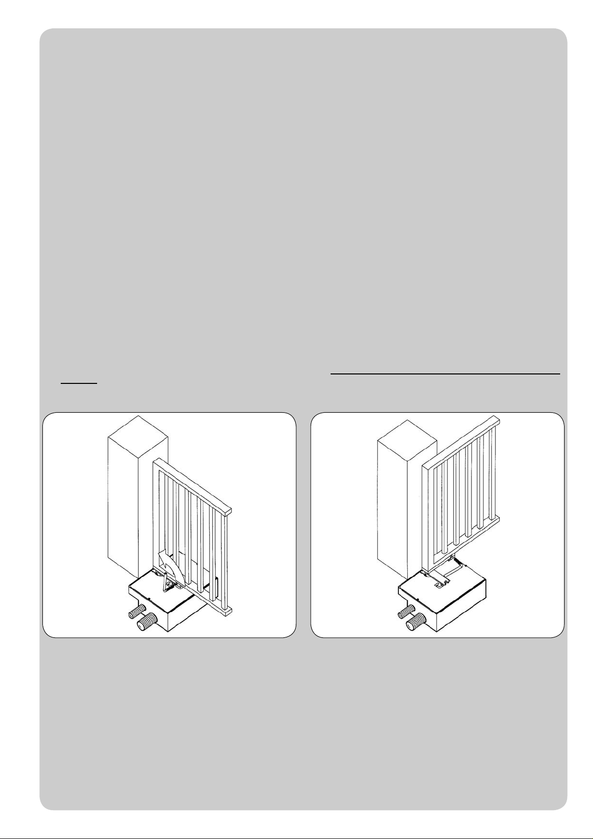
Infilare la chiave a tubo nella leva del cancello e ruotare nel
senso indicato. Quindi aprire il battente del cancello manualmente.
La manovra manuale deve essere eseguita SOLO a porta ferma e DOPO aver tolto l’alimentazione alla centrale elettrica.
Nota: se il vostro impianto è dotato di un telecomando che dopo qualche tempo vi sembra funzionare peggio, oppure non funzionare affato, potrebbe
semplicemente dipendere dall’esaurimento della pila (a seconda del tipo, possono trascorrere diversi mesi fino a 2/3 anni). Ve ne potete accorgere
dal fatto che la spia di conferma della trasmissione è debole, oppure si accende solo per un breve istante. Prima di rivolgervi all’installatore provate
a scambiare la pila con quella di un altro trasmettitore eventualmente funzionante: se questa fosse la causa dell’anomalia, sarà sufficiente sostituire
la pila con un’altra dello stesso tipo.
Nel caso voleste aggiungere nella vostra casa un nuovo tipo di automazione, rivolgendovi allo stesso installatore e alla Tau vi garantirete, oltre che
la consulenza di uno specialista e i prodotti più evoluti del mercato, il migliore funzionamento e la massima compatibilità delle automazioni.
Vi ringraziamo per aver letto queste raccomandazioni, e vi auguriamo la massima soddisfazione dal vostro nuovo impianto: per ogni tipo di esigenza
rivolgetevi con fiducia al vostro installatore.
Italiano

Ut-2
Fit the socket spanner into the gate lever and turn in the
indicated direction Then open the leaf of the gate by hand.
The manual manoeuvre must ONLY be done with the door stopped and AFTER disconnecting power from the electrical control unit.
N.B.: if your remote control unit (if supplied) starts working badly after a time, or does not work at all, the batteries may be flat (they can last from
several months to 2/3 years depending on what type is used). This can be seen from the fact that the transmission confirmation LED gets dimmer
or only turns on for brief moments. Before contacting your fitter, try exchanging the battery with one from a good transmitter: if this is the reason for
the fault, simply replace the battery with another one of the same type.
If you wish to add a new automated system to your house, contact your fitter and we at Tau to have the advice of a specialist, the most developed
products on the market, best operation and maximum automation compatibility.
Thank you for reading these suggestions and we trust you are fully satisfied with your new system: please contact your fitter for any further
requirements.
English
INSTRUCTIONS AND WARNINGS FOR AUTOMATIC SYSTEM USERS
CONGRATULATIONS on choosing a Tau product for your automation system!
Tau S.r.l. produces components for automatic gates, doors, barriers and shutters. These include gear motors, control units, radio control devices,
flashing lights, photocells and accessories.
Tau products are exclusively made with top quality materials and processes and, as a company, we constantly research and develop innovative
solutions in order to make our equipment increasingly easier to use. We also pay great attention to all details (technology, appearance and
ergonomics). The extensive Tau range makes it possible for your fitter to choose the product which best meets your requirements.
Tau, however, does not produce your automated system as this is the outcome of a process of analysis, evaluation, choice of materials and
installation performed by your fitter.
Each automated system is unique, therefore, and only your fitter has the experience and professionalism required to create a system that is
tailor-made to your requirements, featuring long-term safety and reliability, and, above all, professionally installed and compliant with current
regulations.
An automated system is handy to have as well as being a valid security system. Just a few, simple operations are required to ensure it lasts for
years.
Even if your automated system satisfies regulatory safety standards, this does not eliminate “residue risks”, that is, the possibility of dangerous
situations being generated, usually due to irresponsible and/or incorrect use. For this reason we would like to give you some suggestions on how
to avoid these risks:
- Before using the system for the first time: ask your fitter to explain how residue risks can arise and read the instructions and warnings in the
user handbook that your fitter will have given you. Keep this manual for future use and, if you should ever sell your automated system, hand it
over to the new owner.
- Your automated system carries out your commands to the letter: irresponsible and/or incorrect use may cause it to become dangerous. Do
not use the system if people, animals and/or objects enter its operating area.
- IT IS NOT A TOY! Make sure children do not play near the system and keep the remote control device out of their reach.
- Faults: If you notice any abnormal behaviour, disconnect the system from the power supply immediately and perform the manual release
operation (see figure). Do not attempt to repair the door but call in your fitter: the system will operate manually as it did before installation.
- Maintenance: to ensure long life and totally safe operation, the system required routine maintenance, just like any other piece of machinery.
Establish maintenance times together with your fitter. Tau recommends a frequency of 6 months for normal domestic installations but this may
vary depending on the intensity of use (always every 3000 work cycles). It is strictly forbidden to use cleaning equipment, such as high pressure
water cleaners, and/or spray the automatic system with jets of water in general.
N.B.: All controls, maintenance work and/or repairs may only be carried out by qualified personnel.
- Do not modify the plant or the relative programming and adjustment parameters: your fitter will see to that.
N.B. Final testing, routine maintenance and any repairs must be documented by the fitter (in the relative spaces) and such documents
kept by the owner of the system (IF THE DOCUMENTS ARE NOT PRODUCED, THE WARRANTY WILL EXPIRE).
- Disposal: At the end of system life, make sure that it is demolished by qualified personnel and that the materials are recycled or disposed of
according to local regulations.

Ut-3
Den Steckschlüssel in den Torhebel stecken und in der
angegebenen Richtung drehen. Dann den Torflügel von Hand öffnen.
Die manuelle Bewegung darf AUSSCHLIESSLICH bei stehendem Tor und NACH Abschalten der Versorgung zur Steuerung ausgeführt
werden.
Anmerkung: wenn eine Fernbedienung zu IhrerAnlage gehört, die nach einer bestimmten Zeit schlechter oder gar nicht funktioniert, sollten Sie die
Batterie kontrollieren, die ganz einfach leer sein könnte (je nach Typ, kann die Batterie mehrere Monate bis 2-3 Jahre dauern). Sie können das am
Leuchtmelder bemerken, der die Übertragung bestätigt und nur schwach oder ganz kurz aufleuchten wird. Tauschen Sie die Batterie mit der eines
anderen, funktionierenden Senders aus, bevor Sie sich an den Installateur wenden: falls die Ursache der Betriebsstörung eine leere Batterie sein
sollte, genügt es, diese mit einer anderen gleichen Typs zu ersetzen.
Falls Sie Ihrem Haus eine weitere neueAutomatisierung hinzufügen wollen, werden Sie sich bei Ihrem Installateur und bei Tau neben der Beratung
eines Fachmanns die fortgeschrittensten Produkte garantieren, die es auf dem Markt gibt, mit bestem Betrieb und maximaler Kompatibiltät der
Automatisierungen.
Wir danken Ihnen, dass Sie diese Hinweise gelesen haben und wünschen Ihnen volle Zufriedenheit mit Ihrer neuen Anlage. Wenden Sie sich für
jeden Bedarf vertrauensvoll an Ihren Installateur.
Deutsch
ANWEISUNGEN UND HINWEISE FÜR DEN BENUTZER DER AUTOMATISIERUNG
WIR GRATULIEREN IHNEN zur Wahl eines Tau Produktes für Ihre Automatisierung!
Tau S.r.l. stellt Komponenten für die Automatisierung von Toren, Türen, Schranken und Fenstern her: Getriebemotoren, Steuerzentralen,
Funksteuerungen, Blinkleuchten, Fotozellen und Zubehör.
Die Tau Produkte werden nur mit Materialien und Bearbeitungen hoher Qualität hergestellt, und unsere Firma ist auf der ständigen Suche nach
innovativen Lösungen, mit denen die Benutzung unsererApparaturen, die in jeder Hinsicht (Technik,Aussehen und Ergonomie) besonders gepflegt
sind, immer einfacher wird: unter dem großen Tau Sortiment kann Ihr Installateur das Produkt auswählen, das Ihrem Bedarf am besten entspricht.
Tau ist aber nicht der Hersteller Ihrer Automatisierung, die dagegen das Ergebnis des Werks Ihres Vertrauensinstallateurs ist, der sich mit den
notwendigen Untersuchungen und Bewertungen, der Wahl der Materialien und der Verwirklichung die Anlage beschäftigen wird.
JedeAutomatisierung ist daher einzigartig und nur Ihr Installateur kann eineAnlage ausführen, die Ihrem Bedarf entspricht (er besitzt die notwendige
Erfahrung und Professionalität), die sicher und auf Zeit zuverlässig und vor allem fachgerecht ist und mit den gültigen Vorschriften übereinstimmt.
Eine Automatisierungsanlage ist etwas wirklich bequemes, aber auch ein gutes Sicherheitssystem, und mit ein paar einfachen Maßnahmen wird
sie jahrelang dauern.
Auch wenn IhreAutomatisierung dem Sicherheitsniveau entspricht, das von den Vorschriften gefordert wird, schließt dies das Vorhandensein eines
„Restrisikos” nicht aus, bzw. der Möglichkeit, dass Gefahren aufgrund eines fahrlässigen und/oder falschen Gebrauchs erzeugt werden können.
Aus diesem Grund geben wir hier einige Verhaltensweisen an, um diese möglichen Restrisiken zu vermeiden:
- Bei der ersten Benutzung: bitten Sie Ihren Installateur, Ihnen den Ursprung der Restrisiken zu erklären, und lesen Sie die vorliegenden
Anweisungen und Hinweise für den Benutzer, die Ihnen vom Installateur übergeben werden. Bewahren Sie die Anleitung für zukünftige
Probleme auf, und übergeben Sie diese ggf. dem neuen Besitzer der Anlage.
- Die Automatisierungsanlage folgt getreu Ihren Befehlen: ein fahrlässiger und/oder unsachgemäßer Gebrauch kann gefährlich sein.
Betätigen Sie daher die Automatisierung nicht, wenn sich Personen, Tiere und/oder Gegenstände in ihrem Aktionskreis befinden.
- SIE IST KEIN SPIEL! Lassen Sie Kinder nicht in der Nähe der Anlage spielen und halten Sie die Fernbedienungen außer deren Reichweite.
- Störungen: schalten Sie bei jedem ungewöhnlichen Verhalten der Anlage die Stromversorgung zurAutomatisierung ab und entriegeln Sie von
Hand (siehe Abbildung). Vermeiden Sie jeden persönlichen Eingriff und rufen Sie Ihren Installateur: nach dem Entriegeln wird die Anlage von
Hand funktionieren, wie vor der Installation.
- Wartung: um zu dauern und ganz sicher zu funktionieren, bedarf dieAnlage wie jede andere Maschine einer periodischen Wartung. Legen Sie
die Wartungszeiten zusammen mit Ihrem Installateur fest. Tau empfiehlt für den normalen Hausgebrauch eine Wartung alle 6 Monate, was je
nach Gebrauchshäufigkeit unterschiedlich sein kann (immer ungefähr 3000 Arbeitszyklen). Es ist absolut verboten, Geräte wie Hydroreiniger
und ähnliches zur Reinigung zu benutzen und/oder direkten Wasserstrahl auf die Automatisierung zu richten.
N.B.: Eingriffe (Kontrolle, Wartung und/oder Reparatur) dürfen nur von Fachpersonal ausgeführt werden.
- Anlage und programmierte und eingestellte Parameter nicht ändern, das ist Aufgabe des Installateurs.
N.B.: Endprüfung, periodische Wartungsarbeiten und eventuelle Reparaturen müssen von dem, der sie ausführt, belegt sein (in den dazu
bestimmten Feldern); diese Unterlagen muss der Besitzer der Anlage aufbewahren (DIE GARANTIE WIRD UNGÜLTIG, FALLS DIE
DOKUMENTATION FEHLT).
- Entsorgung: stellen Sie am Ende der Lebensdauer derAnlage sicher, dass die Entsorgung durch Fachpersonal erfolgt und dass die Materialien
nach den örtlich gültigen Vorschriften recycled oder entsorgt werden.

Ut-4
Enfiler la clé à tube dans le levier du portail et tourner dans le
sens indiqué. Ouvrir ensuite le portail à la main.
La manœuvre manuelle doit être exécutée UNIQUEMENT avec la porte fermée et APRÈS avoir coupé l’alimentation de l’armoire
électrique.
Note : si votre installation est munie d’une télécommande qui au bout de quelques temps semble moins bien fonctionner ou ne plus fonctionner du
tout, cela peut dépendre tout simplement de la pile (suivant le type sa durée est de plusieurs mois jusqu’à 2/3 ans). Vous pouvez vous en rendre
compte à travers le fait que le voyant de confirmation de la transmission est faible ou bien, s’il ne s’allume qu’un bref instant.Avant de vous adresser
à l’installateur, essayez d’échanger la pile avec celle d’un autre émetteur qui fonctionne correctement : si la cause de l’anomalie est celle-ci, il suffira
de remplacer la pile par une autre du même type.
Si vous désirez ajouter un nouveau type d’automatisme dans votre habitation, adressez-vous au même installateur et à Tau ; en plus du conseil d’un
spécialiste, vous aurez ainsi la garantie des produits les plus évolués sur le marché, du meilleur fonctionnement et du maximum de compatibilité
entre les automatismes.
Nous vous remercions d’avoir lu ces recommandations et nous espérons que votre nouvelle installation vous donnera toute satisfaction : pour tout
type d’exigence, adressez-vous en toute confiance à votre installateur.
Français
INSTRUCTIONS ET RECOMMANDATIONS DESTINÉES À L’UTILISATEUR DE L’AUTOMATISATION
FÉLICITATIONS pour avoir choisi pour votre automatisation un produit Tau !
Tau S.r.l. produit des composants pour l’automatisation de portails, portes, barrières, volets : opérateurs, logiques de commande, radiocommandes,
clignotants, photocellules et accessoires.
Les produits Tau sont réalisés exclusivement avec des matériaux et des usinages de qualité et en tant qu’entreprise, nous sommes à la recherche constante
de solutions innovantes qui simplifient de plus en plus l’utilisation de nos appareils, soignés sur tous les plans (technique, esthétique et ergonomique) : dans
la vaste gamme Tau, votre installateur peut choisir le produit qui satisfera au mieux vos exigences.
Tau toutefois ne produit pas votre automatisation qui est, en fait, le résultat d’un travail d’analyse, d’évaluation, de choix des matériaux et de réalisation de
l’installation effectué par votre installateur de confiance.
Chaque automatisation, par conséquent, est unique et seul votre installateur peut réaliser une installation suivant vos exigences (dans la mesure où il est
doté de l’expérience et de la qualification professionnelle nécessaire), sûre et fiable dans le temps et, surtout, effectuée dans les règles de l’art, c’est-à-dire
conforme aux normes en vigueur.
Une installation d’automatisation est d’une grande commodité, en plus de représenter un système de sécurité et, avec un minimum d’attentions, elle est
destinée à durer des années.
Même si l’automatisme en votre possession satisfait le niveau de sécurité requis par les normes, cela n’exclut pas l’existence d’un “risque résiduel”, c’est-à-
dire la possibilité que des situations de danger puissent se vérifier, à cause d’une utilisation non raisonnable et/ou erronée. Pour cette raison, nous donnons
quelques conseils sur les comportements à suivre pour éviter tout inconvénient :
- À la première utilisation : demandez à votre installateur de vous expliquer l’origine des risques résiduels et lisez ce manuel d’instructions et de
recommandations pour l’utilisateur qui vous a été remis par l’installateur. Conservez le manuel pour tout problème futur et n’oubliez pas de le remettre
à l’éventuel nouveau propriétaire de l’installation.
- L’installation d’automatisation exécute fidèlement vos commandes : une utilisation non raisonnable et/ou impropre peut devenir dangereuse.
Évitez par conséquent d’actionner l’automatisme quand des personnes, des animaux ou des objets se trouvent dans son rayon d’action.
- CE N’EST PAS UN JEU ! Faites en sorte que les enfants ne jouent pas à proximité de l’installation et conservez les télécommandes hors de leur
portée.
- Anomalies: à tout comportement anormal de l’installation, coupez l’alimentation électrique de l’automatisme et effectuez le déblocage manuel (comme
sur la figure). Évitez toute intervention personnelle et contactez votre installateur : une fois débloquée, l’installation fonctionnera manuellement, comme
avant l’automatisation.
- Maintenance : pour durer dans le temps et fonctionner en toute sécurité, comme toute autre machine, l’installation a besoin d’une maintenance
périodique. Établissez avec votre installateur un plan de maintenance. Tau conseille une intervention tous les 6 mois pour un usage domestique normal
qui peut varier suivant l’intensité d’utilisation (toujours tous les 3000 cycles de travail).
Il est absolument interdit d’utiliser des équipements pour le
lavage tels que des nettoyeurs haute pression ou similaires et/ou d’orienter des jets d’eau en général directement sur l’automatisme.
N.B. N’importe quel type d’intervention (contrôle, maintenance et/ou réparation) doit être effectué uniquement par du personnel qualifié.
- Ne pas modifier l’installation ni les paramètres de programmation et de réglage : la responsabilité en incombe à l’installateur.
N.B. l’essai de fonctionnement final, les maintenances périodiques et les éventuelles réparations doivent être documentées (dans les espaces
prévus à cet effet) par qui les exécute et les documents doivent être conservés par le propriétaire de l’installation (EN CASE DE NON-
PRÉSENTATION DE LA DOCUMENTATION, LA GARANTIE N’EST PLUS VALABLE).
- Démantèlement : à la fin de la vie de l’installation, assurez-vous que le démantèlement soit effectué par du personnel qualifié et que les matériaux
soient recyclés ou mis au rebut suivant les normes en vigueur au niveau local.

13
R30 - R40
1 2
230mm
380mm 223mm
144mm
230mm
354mm 223mm
144mm
R40 - 12 Vd.c. R30 - 230 Va.c.
3
R40 - 12 Vd.c. R30 - 230 Va.c.
4
- - -- - - - - - - - - - - - - - - - - - - - - - - - - - - - - - - - - - - - - - - - - - - - - - - - - - - - - - - - - - - - - - - - - - - - - - - - - - - - - - - - - - - - - - - - - - - - - -
R30 - R40
DISEGNI - DRAWINGS - ZEICHNEN - PROJETS - DIBUJOS

14
R30 - R40
5 6
19mm
10mm
2mm
6mm
Ø10mm
Ø5mm
17mm
R 30 - 230V a.c.
R 40 - 12V d.c.
Optional
COPERCHIO
DECKEL
COVER
COUVERCLE
TAPA
55 mm
225 mm
92 mm
154 mm 58 mm
8 mm
245 mm
320 mm
207.5 mm 207.5 mm
415 mm
7
12
5mm 63mm
55 mm
150mm
1
2
3
4
56
7
8
FINITO
LIVELLO
PAVIMENTO
8mm
8
R30 - R40
DISEGNI - DRAWINGS - ZEICHNEN - PROJETS - DIBUJOS

15
R30 - R40
12 1
3
2
1
3
2
10
9
ANTA
R30 - R40
DISEGNI - DRAWINGS - ZEICHNEN - PROJETS - DIBUJOS
11

16
R30 - R40
1413
15/B
5mm
LIVELLO PAVIMENTAZIONE
FLUßBODENEBENE
FLOOR LEVEL
NIVEAU DU SOL
NIVEL DEL PAVIMENTO
DRENAGGIO ACQUA OBBLIGATORIO
WASSERRDRAINAGE IS PFLICHT
COMPULSORY WATER DRAINAGE
DRENAGE DE L'EAU
DESAGUE DEL AGUA OBLIGATORIO
IP 65
15/A 16
17
12
55 mm
INGRASSATORE
GREASE NIPPLE
FETTBÜCHSE
GRAISSEUR
ENGRASADOR
- - -- - - - - - - - - - - - - - - - - - - - - - - - - - - - - - - - - - - - - - - - - - - - - - - - - - - - - - - - - - - - - - - - - - - - - - - - - - - - - - - - - - - - - - - - - - - - - -
R30 - R40
DISEGNI - DRAWINGS - ZEICHNEN - PROJETS - DIBUJOS
Other manuals for R30
1
This manual suits for next models
1
Table of contents
Other tau Gate Opener manuals


