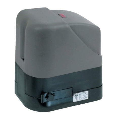
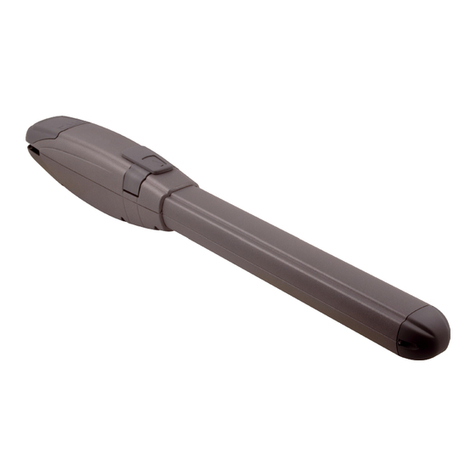
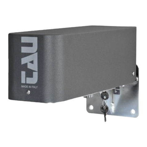
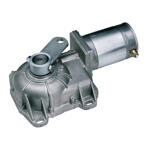
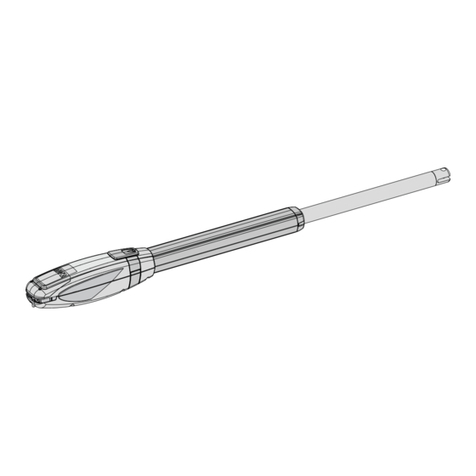
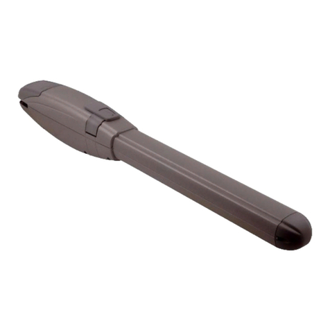
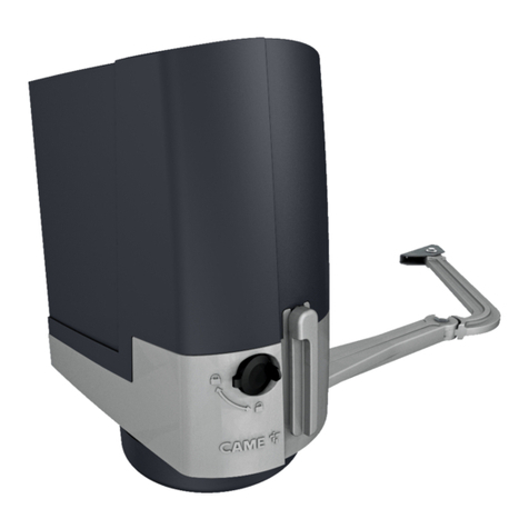
tau ZIPPO User manual

USE AND MAINTENANCE MANUAL
ZIPPO
Automations for swing gates
Via Enrico Fermi, 43 - 36066 Sandrigo (VI) Italia
Tel +39 0444 750190 - Fax +39 0444 750376 - info@tauitalia.com - www.tauitalia.com
D-MNL0ZIPPOXL-GB 15-11-2017 - Rev.01
IT - Istruzioni originali

ZIPPOXL
2
ZIPPO XL XLB XLB-R
Alimentazione / Power / Stromspeisung / Alimentation / Alimentación 230V AC
Frequenza / Frequency / Frequenz / Fréquence / Frequencia 50/60 Hz
Condensatore / Capacitor / Kodensator / Condensateur / Condensador 12,5 µf - -
Motore / Motor / Motor / Moteur / Motor 230V AC 12V DC 24V DC
Tempo di apertura 90° / Opening time 90° / Laufzeit, 90°
Temps de ouverture 90° / Tiempo de apertura 90° 16,5 sec. 16,5 sec. 10 sec.
Assorbimento / Absorption / Stromentnahme / Absorption / Absorción 1,4 A 1,3 A 1,5 A
Potenza assorbita / Absorbed rated power / Aufgenommene Leistung
Puissance absorbée / Potencia nominal absorbida 260 W 300 W
Rapporto di riduzione / Reduction ratio / Übersetzungsverhältnis
Rapport de réduction / Relación de reducción 1/1175
Intervento di termoprotezione / Thermal protection trips at / Eingreifen des Warmeschutzes
Intervention protection thermique / Interventiòn termoprotecciòn 160°C
Grado di protezione / Protection level / Schutzart
Degré de protection / Grado de protección IP 44
Ciclo di lavoro / Working cicle / Arbeitzyklus / Cycle de travail / Ciclo de trabajo 50% 100%
Temperatura di esercizio / Operating temperature / Betriebstemperatur
Température de fonctionnement / Température de fonctionnement -20°C + 55°C
Coppia max / Max torque / Max Motordrehmoment / Couple max / Par màx 402 Nm 458 Nm
Lunghezza max. semi-anta / Max. length of half-leaf / Max. halb Torügellänge
Longueur max. demi-battant / Longitud max. media-hoja 4 mt
Peso max. anta / Max. leaf weight / Flügelgewicht max. - Poids max battant
Peso máximo de la hoja 400 Kg
Peso / Weight / Gewicht / Poids / Peso 21 Kg
Description and characteristics
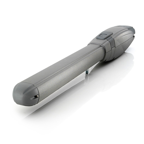
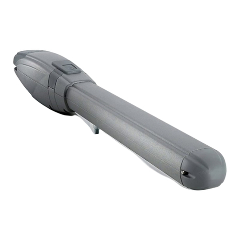
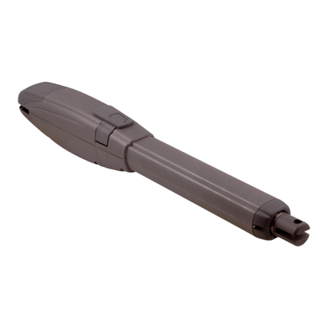
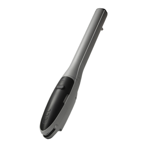
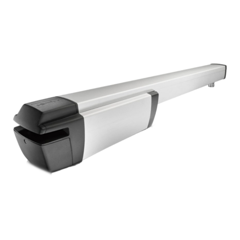
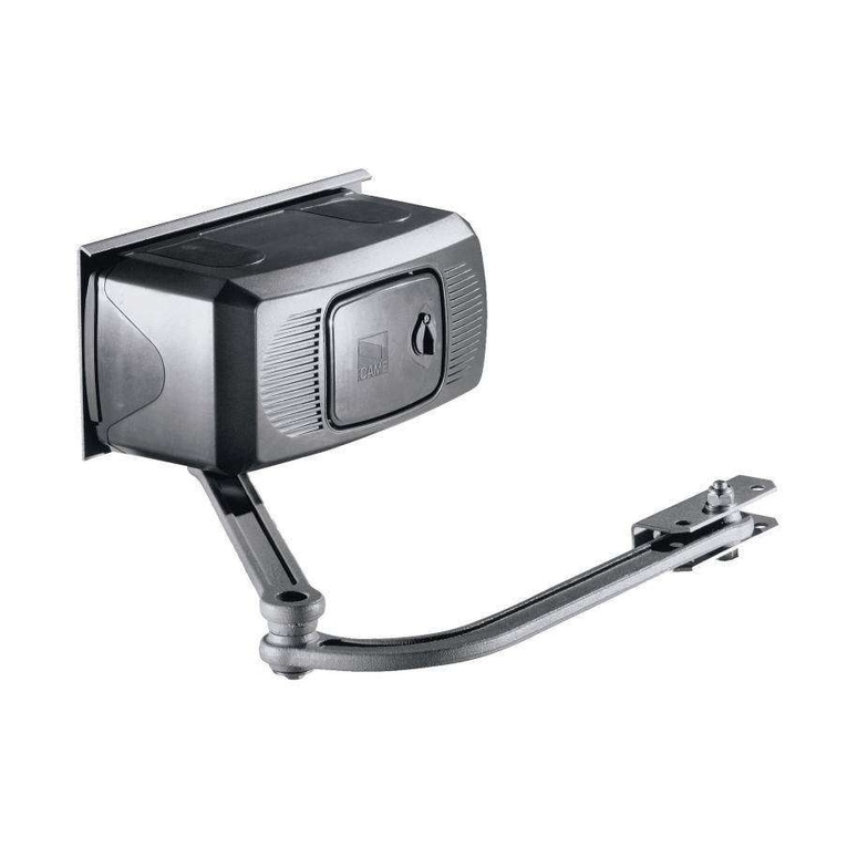
The automation ZIPPO XL have been designed to move swing gates.
THE USE OF THE EQUIPMENT FOR PURPOSES OR CIRCUMSTANCES OTHER THAN THOSE MENTIONED IS STRICTLY
PROHIBITED.
English
The data described in this handbook are purely a guide. TAU reserves the right to change them in any moment.
The manufacturer reserves the right to modify or improve products without prior notice. Any inaccuracies or errors found in this
handbook will be corrected in the next edition.
When opening the packing please check that the product is intact. Please recycle materials in compliance with current regulations.
This product may only be installed by a qualied tter. The manufacturer declines all liability for damage to property and/or
personal injury deriving from the incorrect installation of the system or its non-compliance with current law (see Machinery
Directive).

ZIPPOXL
3
MANUFACTURER’S DECLARATION OF INCORPORATION
(in accordance with European Directive 2006/42/EC App. II.B)
Manufacturer: TAU S.r.l.
Address: Via E. Fermi, 43
36066 Sandrigo (Vi)
ITALY
Declares under its sole responsibility, that the product: Electromechanical actuator
designed for automatic movement of: Industrial Doors
for use in a: Industrial environment
complete with: -
Model: ZIPPO XL
Type: ZIPPO XL / XLB / XLB-R
Serial number: SEE SILVER LABEL
Commercial name: AUTOMATION FOR INDUSTRIAL DOORS
Has been produced for incorporation on an access point (industrial door) of for assembly with other devices used to move such an
access point, to constitute a machine in accordance with the Machinery Directive 2006/42/EC.
Also declares that this product complies with the essential safety requirements of the following EEC directives:
- 2014/35/EU Low Voltage Directive
- 2014/30/EU Electromagnetic Compatibility Directive
Also declares that it is not permitted to start up the machine until the machine in which it is incorporated or of which it will be a
component has been identied with the relative declaration of conformity with the provisions of Directive 2006/42/EC.
The following standards and technical specications are applied:
EN 61000-6-2; EN 61000-6-3; EN 60335-1; EN 300 220-2 V2.4.1;
EN 12453:2000; EN 12445:2000; EN 60335-2-103.
The manufacturer undertakes to provide, on sufciently motivated request by national authorities, all information pertinent to the
partly completed machinery.
Sandrigo, 15/11/2017
Legal Representative
_________________________________________
Loris Virgilio Danieli
Name and address of person authorised to draw up all pertinent technical documentation:
Loris Virgilio Danieli - via E. Fermi, 43 - 3606 Sandrigo (Vi) Italia

ZIPPOXL
4
INSTALLATION WARNINGS
GENERAL SAFETY REQUIREMENTS
1) Carefully read all instructions before installation, as
they provide important instructions regarding the safe-
ty, installation, operation and maintenance. Incorrect
installation or use of the product may lead to serious
physical injury.
2) Never leave packaging materials (plastic, polystyrene etc.)
within the reach of children as they constitute a potential
hazard.
3) Keep the instructions in a safe place for future consultation.
4) This product has been designed and constructed exclu-
sively for the use specied in this documentation. Any other
use not specied herein may impair product integrity and/or
constitute a hazard.
5) TAU Srl declines all liability for improper use or use other
than as specied for this automation.
6) Do not install the unit in an explosive environment: the pres-
ence of either gas or ammable fumes is a serious safety risk.
7) The mechanical elements must comply with the require-
ments as stated in the standards EN 12604 and EN 12605.
For non European member states, in addition to the national
reference standards, the above-mentioned standards must
be observed to ensure an adequate level of safety.
8) TAU Srl is not responsible for failure to observe Good Prac-
tice in construction of the gates/doors to be power-operated,
nor any deformations occurring during use.
9) Installation must be performed in compliance with the stand-
ards EN 12453 and EN 12445. For non European member
states, in addition to the national reference standards, the
above-mentioned standards must be observed to ensure an
adequate level of safety.
10) Before performing any operations on the system, discon-
nect from the mains and detach the batteries.
11) On the automation power line, install a device for discon-
nection from the power mains with a gap between contacts
equal to or greater than 3 mm. Use of a 6A thermal magnetic
circuit breaker with multi-pole switch is recommended.
12) Check upline of the system that there is a residual current
circuit breaker with a threshold of 0.03 A.
13) Ensure that the earthing system is to professional standards
and connected to the metal section of the gate/door.
14) The automation is equipped with an intrinsic anti-crushing
safety device comprising a torque control. The trip thresh-
old must in all cases be checked as stated in the standards
specied in point 9.
15) The safety devices (standard EN 12978) enable the protec-
tion of danger areas from risks associated with mechani-
cal movements such as crushing, dragging and shearing.
16) The use of at least one luminous indicator is recommended
for each system, as well as a warning notice xed suitably
to the frame structure, in addition to the devices specied in
point 15.
17) TAU declines all liability for the safety and efcient operation
of the automation in the event of using system components
not produced by TAU.
18) For maintenance, use exclusively original TAU parts.
19) Never modify components that are part of the automation system.
20) The installer must provide all information regarding manual
operation of the system in the event of an emergency and
supply the system User with the “User Guide” enclosed with
the product.
21) Never allow children or other persons to stay in the vicinity
of the product during operation.
22) Keep all radio controls or other pulse supplier device out of
the reach of children to prevent inadvertent activation of the
automation.
23) Transit should only occur with the automation stationary.
24) The user must never attempt to repair or intervene directly
on the product; always contact qualied personnel for as-
sistance.
25) It is strictly forbidden to use high pressure water cleaners or
jets of water in general to clean the automation.
25) Maintenance: at least every six months, make a general
check of the system, with special reference to the efciency
of the safety devices (including, when envisaged, the opera-
tor thrust force) and release mechanisms.
26) All actions not expressly envisaged in these instruc-
tions are strictly prohibited.
1_ CONDITIONS OF USE
The ZIPPO XL automation for swing gates has been designed for
industrial and domestic use.
2_ OVERALL DIMENSIONS
The main dimensions of the automation with telescopic arm are
indicated in pic. # 1 and # 2.
3_ INSTALLATION
Installation must be carried out by skilled and quali-
ed personnel in compliance with the regulations in
force.
3.1_ Preliminary checks
Prior to installing the operator, make all structural modications in
order to ensure safety distances and protect and segregate areas
in which people may be exposed to the risk of crushing, shearing,
dragging or similar dangers.
•
Make sure the existing structure is sufciently sturdy and stable;
• the mechanical parts must conform to the provisions of Stand-
ards EN 12604 and EN 12605;
• leaf length and leaf weight in compliance with the actuator
specications;
• regular and uniform movement of the leaves, without any fric-
tion and dragging during their entire travel;
• stiff hinges in good conditions;
• presence of an efcient earthing for electrical connection of
the actuator.
Perform any necessary metalwork job before installing the operator.
The preliminary checks are REQUIRED. It is expressly
forbidden to install the product on doors in poor con-
dition or not properly mantained.
The condition of the door structure directly affects the reli-
ability and safety of the gate operator.
3.2_ Cables typology
Connection Type of
cable
Cable l.
1 < 10 m
Cable l.
10 < 20 m
Cable l.
20 < 30 m
230v supply
FG70R
CEI 20-22
CEI EN
50267-2-1
3 x 1,5 mm² 3 x 2,5 mm² 3 x 4 mm²
Photocell trans-
mitters 2 x 0,5 mm² 2 x 0,5 mm² -
Photocell
receivers 4 x 0,5 mm² 4 x 0,5 mm² -
Accessory
24v power
supply
2 x 0,5 mm² 2 x 1 mm² -
Control devices 2 x 0,5 mm² 2 x 0,5 mm² 2 x 0,5 mm²
Aerial RG58 See relative instructions
Metal mass
sensor See relative instructions
NOTE: If the length of the cables is not as stated in the table,
determine the cable section on the basis of the real draw of
the connected devices and in compliance with the IEC EN
60204-1 Standard.
As to connections with numerous loads on the same line (in
sequence), dimensions must be recalculated on the basis of
the real draw and distance. As to the connection of any prod-

ZIPPOXL
5
ucts not dealt with in this manual, the documents attached to
the products themselves must be consulted.
3.3_ Typical system (pic. # 12-13)
1 ZIPPO XL Motor
2 Control Panel
3 Pair of wall photocells
4 Flashing light with aerial
5 Pair of photocells with mounting post
6 Key switch
3.4_ Motor positioning
Note: this refers to the right motor (RX) that installed
on the wing right seen from inside the room.
Fig.1 shows the measures for the holes to be made on the pillar
to x the motor frame (1) and on the leaf for
x the articulated arm bracket (2)
Proceed as follows:
1_ install the motor frame (1) as shown in Fig. 3.
Note: the bracket holes (2) must be 100mm below the
upper holes of the xing motor plate (1) as in g. 1.
Once mounted the motor plate 1, proceed with xing the motor
operating as follows (g. 4):
3_ position the gearmotor A on the plate by inserting the output
shaft B on the C hole and secure it with the supplied screws.
3.5_ Insertion of articulated arm
To apply the articulated arm to the motorgear, proceed as follows:
1_ Insert the operator lever D on the drive shaft and x the articu-
lated joint through the provided screw and nut E (picture 5)
2_ Assemble through the provided screw the second part of the
articulated arm F (picture 6)
3_ Assemble through the provided screw and nut the third part of
the articulated arm G (picture 7).
Keep a maximum angle of 170° between the articulated arm
connected to the operator and the part of the arm G, in order
to make the movements of the operator easier (picture 2)
4_ After having assembled the articulated arm, adjust the length
and x it to the anchor plate (picture 1)
5_ Close the automation through the provided cover (picture 8)
3.6_ Switch adjustment
Motor LX (seen from inside the room)
Opening: release the actuator (see par. “Manual release”) and
move the leaf to the required open position. Turn the opening cam
clockwise until the micro-switch trips and secure it with the central
screw (pic. # 10).
Closing: move the leaf to the required closed position. Turn the
closing cam anticlockwise until the micro-switch trips and secure
it with the central screw (pic. # 10).
Motor RX (seen from inside the room)
Opening: release the actuator (see par. “Manual release”) and
move the leaf to the required open position. Turn the opening cam
anticlockwise until the micro-switch trips and secure it with the
central screw (pic. # 10).
Closing: move the leaf to the required open position. Turn the
closing cam clockwise until the micro-switch trips and secure it
with the central screw (pic. # 10).
Whenever the position of the microswitch stops is
modied, it is advisable to repeat the saving proce-
dure on the control board (see D760M instructions).
3.7_ Electrical connections (pic. # 9)
ZIPPO
POS. COLOR DESCRIPTION
3 Yellow / Green Grounding
4 Dark Blu
Phase
1 +
Cap
.
5 Light Blue Motor common
6 Grey
Phase
2 +
Cap
.
Use only control units with electric clutch.
The distance between the control unit and the motor must not
exceed 10 – 12 m.
TAU srl recommends its composite cable, Code M-03000010CO;
Place the control unit in the immediate vicinity of the
motors.
Be careful not to run cables for auxiliary devices in-
side raceways housing other cables supplying pow-
er to large loads or lights with electronic starters.
In the event control pushbuttons or indicator lights
are installed inside homes or ofces several metres
away from the actual control unit, it is advisable to
decouple the signal by means of a relay in order to
avoid induced interference.
CAUTION-If during the memorization process one or
both of the doors close instead of opening, stop the
automations and reverse the polarity of the motor.
4_ USE
The ZIPPO XL automation has been designed for swing gates
with leaves max. 3 mt. long and weight max of 200 Kg.
It is categorically forbidden to use the equipment for
any other use or under circumstances different from
those mentioned herein.
The electronic unit (that must have the built-in electric clutch)
normally makes it possible for you to choose from:
automatic : a command pulse will open and shut the door
semiautomatic : a command pulse will open or shut the door
If there is a blackout to control it manually rst operate the unlock
mechanism.
Furthermore, it also comprises electrical equipment and therefore
must be approached and used with caution and foresight. In par-
ticular we recommend:
• not to touch the equipment with wet hands and/or bare or wet
feet;
• not to perform the automatic or semiautomatic function in the
presence of known or suspected malfunctions;
• not to pull the cable to disconnect the equipment;
• not to let children, or those unable, use the cabinet keys or
controls (including remote controls) even if only to play with;
• do not touch the motor unless you are certain it is cold;
• only operate the door when it is completely visible;
• not to enter within the operating range while it is moving, wait
for it to stop;
• not to let children or animal play within the operating range of
the door;
• to perform periodic maintenance by specialised personnel;
• if there is a fault, turn off the power supply. Use the manual
manoeuvre only if safe. Do not attempt to resolve the problem
yourself, contact a qualied technician of the manufacturer or
authorised by the manufacturer. In any case, make sure that
the spare parts are original so that the safety of the automa-
tion is not compromised.
4.1_ Manual release
In case you need to manually move the door, due to lack of
electricity or automation fault, you must use the release device
as follows:
1_ Take the protection cap out (picture 11)
2_ Insert the provided tube key B in the hole of the lever of the
gate and turn it in the specied direction (picture 11);
3_ Move the unlocked leaf manually.
In order to restore the standard working of the automation, hook

ZIPPOXL
6
again the articulated arm to the operator.
Note: To prevent an involuntary pulse from activating
the gate during the maneuver, before re-locking, turn
off the power.
5_ MAINTENANCE
The ZIPPO's actuators need very little maintenance. However,
to ensure they always work properly, the door has to be in good
condition: hence we shall describe briey what you need to do to
keep your articuilated door efcient.
ATTENTION: no one, except the person who services the
equipment (who must be a specialised technician), should be
able to command the automatism during servicing. Consequently,
it is advisable to turn the electricity off at the mains also to
avoid possible electric shocks. If the electricity has to be on
for certain checks, check or disable all command devices
(remote controls, push button panels, etc.) except for the device
being used by the maintenance person.
Routine maintenance
Each of the following operations must be carried out when the
need arises and, in all cases, every 6 months (always 750 work
cycles).
Articuled door
• Lubricate the hinges and telescopic arms.
Automation system
• check the safety devices (photocells, etc.). They must work
properly in dangerous situations and cut in as congured
during installation;
• check that the slide way is clean and free from debris;
• push the door fully open making sure never to use a force of
more than 150 N (15 kg);
• make sure the door moves smoothly;
• check that the screw connections are perfectly tight.
FREQUENCY: every 750 manoeuvres or 6 months, failing which
the guarantee lapses.
Extraordinary maintenance or breaks
• In case of unusual repairs on mechanic parts, we kindly ask
to remove only the damage part in order to allow headquarter
technicians or authorized ones to repair or x easily the faulty
part.
6_ SCRAPPING
All materials must be disposed of in observance of current stand-
ards.
If the automation is to be scrapped there are no particular dan-
gers or risks associated with the automation itself.
In the case of material recovery, separate components accord-
ing to the waste category (electrical parts - copper - aluminium
- plastic, etc.).
7_ DISASSEMBLY
If the automation is disassembled for subsequent re-assembly in
another site:
- Disconnect the power supply and the entire electrical system;
- Remove the gearmotor from the xing base;
- Disassemble all system components;
- If some components cannot be removed or are damaged, re-
place.
GUARANTEE: GENERAL CONDITIONS
TAU guarantees this product for a period of 24 months from the
date of purchase (as proved by the sales document, receipt or
invoice).
This guarantee covers the repair or replacement at TAU’s ex-
pense (ex-works TAU: packing and transport at the customer’s
expense) of parts that TAU recognises as being faulty as regards
workmanship or materials.
For visits to the customer’s facilities, also during the guarantee
period, a “Call-out fee” will be charged for travelling expenses
and labour costs.
The guarantee does not cover the following cases:
• If the fault was caused by an installation that was not
performed according to the instructions provided by the
company inside the product pack.
• If original TAU spare parts were not used to install the
product.
• If the damage was caused by an Act of God, tampering,
overvoltage, incorrect power supply, improper repairs, in-
correct installation, or other reasons that do not depend on
TAU.
• If a specialised maintenance man does not carry out rou-
tine maintenance operations according to the instructions
provided by the company inside the product pack.
• Wear of components.
The repair or replacement of pieces under guarantee does not
extend the guarantee period.
In case of industrial, professional or similar use, this warranty is
valid for 12 months.

ZIPPOXL
7
200
105
78
100
200
105
238
135
12.5
100
150
10.5
1 2
238
231
350
240
439.5
236
450
D
B
A
C
L
200
105
78
100
200
105
238
135
12.5
100
150
10.5
1 2
238
231
350
240
439.5
236
450
D
B
A
C
L
ZIPPO XL
DISEGNI - DRAWINGS - ZEICHNEN - PROJETS - DIBUJOS
g. / pic. # / Abb. / image / imagen 1
g. / pic. # / Abb. / image / imagen 2
Staffa di ancor-
aggio a pilastro
Fixing bracket
on the pillar
Staffa di ancoraggio per braccio articolato su anta
Fixing bracket for articulated arm
A= 300 mm MAX
B= 500 mm MAX
C= 40 mm
D= 170° MAX
L= 1750 mm MAX

ZIPPOXL
8
ZIPPO XL
DISEGNI - DRAWINGS - ZEICHNEN - PROJETS - DIBUJOS
g. / pic. # / Abb. / image / imagen 3
g. / pic. # / Abb. / image / imagen 5
g. / pic. # / Abb. / image / imagen 4
g. / pic. # / Abb. / image / imagen 6
g. / pic. # / Abb. / image / imagen 7 g. / pic. # / Abb. / image / imagen 8
A
F
G
B
C
D
E

ZIPPOXL
9
ZIPPO XL
DISEGNI - DRAWINGS - ZEICHNEN - PROJETS - DIBUJOS
g. / pic. # / Abb. / image / imagen 9
g. / pic. # / Abb. / image / imagen 10
3 Messa a terra (giallo/verde)
Grounding (yellow/green)
Erdung (Gelb/Grün)
Mise à la terre (jaune/vert)
Puesta a tierra (amarillo/verde)
4 Fase1 + cond + com FCA (blu scuro)
Phase1 + cap + com OLS (dark blu)
Phase1 + Kond + Gem ETA (dunkelblau)
Phase1 + cond + com FCO (bleu foncé)
Fase1 + cond + com FCA (azul oscuro)
5 Comune motore (azzurro)
Motor common (light blue)
Sammelkontakt (blau)
Commun moteur (bleu)
Común motor (azul)
6 Fase2 + cond + com FCC (grigio)
Phase2 + cap + com CLS (grey)
Phase2 + Kond + Gem ETZ (Grau)
Phase2 + cond + com FCF (gris)
Fase2 + cond + com FCC (gris)
B
B
M
Open
Com
Close
To the
Control panel
B
M
Open
Com
Close
To the
Control panel
MOTORE ZIPPO XL VISTO DALL’ALTO - ZIPPO XL OPERATOR (TOP VIEW)
Camma di chiusura
Cam closing
Camma di apertura
Cam opening
Camma di apertura
Cam opening
DXSX

ZIPPOXL
10
6
ZIPPO XL
DISEGNI - DRAWINGS - ZEICHNEN - PROJETS - DIBUJOS
IMPIANTO TIPO CON ANTE BATTENTI DALL'INTERNO - INSTALLATION TYPE INSIDE_SWNG LEAFS
IMPIANTO TIPO CON ANTE BATTENTI DALL'ESTERNO - INSTALLATION TYPE OUTSIDE_SWING LEAFS
g. / pic. # / Abb. / image / imagen 12
g. / pic. # / Abb. / image / imagen 11
1
1
2
3
3
4
5
5
1Motore ZIPPO XL
2Centrale di comando
3Coppia di fotocellule a parete
4Lampeggiante e antenna
5Coppia di fotocellule su colonnina
6Selettore a chiave
A
B

ZIPPOXL
11
ZIPPO XL
DISEGNI - DRAWINGS - ZEICHNEN - PROJETS - DIBUJOS
g. / pic. # / Abb. / image / imagen 13
1
1
2
3
3
4
5
5
IMPIANTO TIPO CON CANCELLO A 4 ANTE - RESIDENTIAL FOLDING GATE. TYPICAL INSTALLATION
1Motore ZIPPO XL
2Centrale di comando
3Fotocellule a parete
4Lampeggiante e antenna
5Coppia di fotocellule su colonnina

Via Enrico Fermi, 43
36066 Sandrigo (VI) - Italy
Tel +39 0444 750190
Fax +39 0444 750376
www.tauitalia.com
Other tau Gate Opener manuals
