TBB power DM Series User manual


Dual/single outputs booster charger

Dual/single outputs booster charger
WARNING: HIGH VOLTAGE INSIDE
CAUTION: THE DC FUSE MUST HAVE BEENTURNED OFF BEFORE SERVICING
MADE IN CHINA

Dual/single outputs booster charger
Disclaimer
Unless specially agreed in writing, TBB Power Co., Ltd.
Takes no warranty as to the accuracy, sufficiency of suitability of any technical or other
information provided in this manual or other documentation.
Assumes no responsibility or liability for loss or damage, whether direct, indirect, consequential
or incidental, which might arise out of the use of such information.
Offers standard warranty with its products, taking no responsibility for direct or indirect loss due
to equipment failure.
About this Manual
This manual describes the features of the dual/single outputs booster charger , and provides the
procedure of installations. This manual is for anyone intending to install our product.
General Instruction
Thanks for choosing our products and this manual is suitable for dual/single outputs booster
charger.
This chapter contains important safety and operation instructions. Read and keep this User Guide
well for later reference.
This system needs to be installed by professionals with enough knowledge of electrical system.
Please pay attention to the following points prior to installation:
1) Please check the input voltage is same to the nominal input voltage of this unit.
2) Upon connection with Alternator, battery and fridge/load, please double confirm the polarity.
3) Please use the shortest possible cable to connect and ensure the secure connection.
4) While connecting, please secure the connection and avoid short circuit between positive
terminal and negative terminal.
5) The unit will have high voltage inside. Only authorized electrician can open the case.
6) The unit WAS NOT designed to use in any life retaining equipment.

Dual/single outputs booster charger
Contents
1. General Safety Instruction...........................................................................................................1
2. Introduction.................................................................................................................................2
2.1 General introduction...........................................................................................................2
2.2 Topology ............................................................................................................................3
2.3 Booster mode logic ............................................................................................................4
2.4 TBB Premium II five stages charging algorithm..................................................................5
2.5 Battery temperature compensation ....................................................................................5
2.6 Back-charging function.......................................................................................................6
2.7 De-rate curve against temperature increase ......................................................................7
3. Structure and dimension .............................................................................................................8
3.1 Exterior and dimension ......................................................................................................8
3.2 Connectors and terminals ..................................................................................................9
3.3 LED indication..................................................................................................................10
4. Installation................................................................................................................................. 11
4.1 Material checking............................................................................................................. 11
4.2 Prepare harness .............................................................................................................. 11
4.3 Proper installation location...............................................................................................12
4.4 Installation space.............................................................................................................12
4.5 Mounting holes.................................................................................................................13
4.6 Auxiliarybattery type and fridge load work mode setting...................................................13
4.7 Cable connection.............................................................................................................15
5. FAQ ..........................................................................................................................................17
6. Specification..............................................................................................................................18

Dual/single outputs booster charger
1
1. General Safety Instruction
Safety Instruction
As dangerous voltage and high temperature exist within the charge controller, only qualified and
authorized maintenance personnel are permitted to open and repair it.
This manual contains information concerning the installation and operation of the charge controller.
All relevant parts of the manual should be read prior to commencing the installation. Please follow
the local stipulation meantime.
Any operation against safety requirement or against design, manufacture, safety standard, and are
out of the manufacturer warranty.
General Precaution
Do not expose to rain, snow or liquids of any type,it is designed for indoor use.
To avoid fire and electric shock, make sure all cables selected with right gauge and being
connected well. Smaller diameter and broken cable are not allowed to use.
Please do not put any inflammable goods near to charge controller.
Never place unit directly above batteries, gases from a battery will corrode and damage the
charge controller.
Do not place battery over charge controller.
Precaution regarding battery operation
Use plenty of fresh water to clean in case battery acid contacts skin, clothing, or eyes and
consult with doctor as soon as possible.
The battery may generate flammable gas during charging. Never smoke or allow a spark or
flame in vicinity of a battery.
Do not put the metal tool on the battery, spark and short circuit might lead to explosion.
Remove all personal metal items such as rings, bracelets, necklaces, and watches while
working with batteries. Batteries can cause short-circuit current high enough to make metal
melt, and could cause severe burns.

Dual/single outputs booster charger
2
2. Introduction
2.1 General introduction
TBB’s DM series charger is an in-vehicle charging solution which specified designed for on-board
application such as RV, Marine, Utility Vehicle, Truck etc.
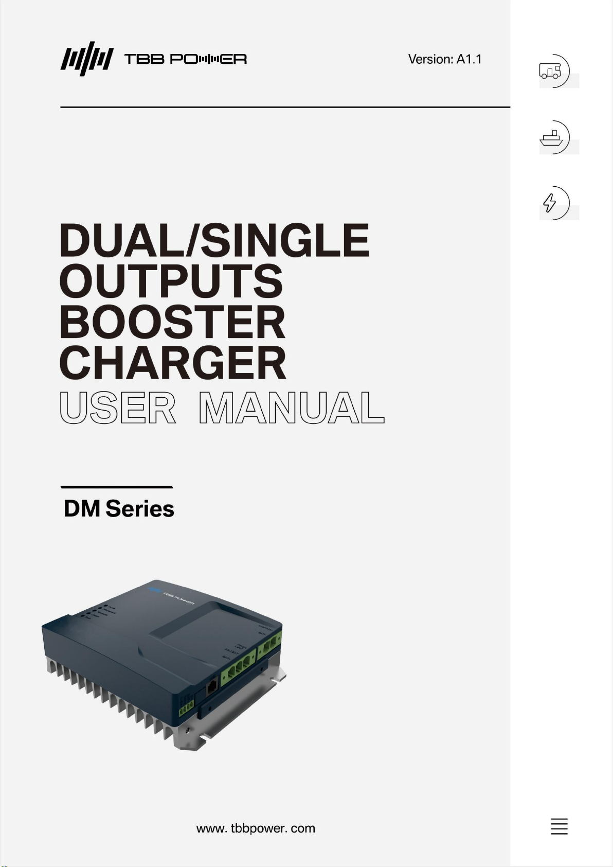
Dual outputs DMT1250 comes with a brilliant feature of dual outputs: one is for auxiliary battery
charging with charge current up to 30A, and the other one is dedicated to power a DC load
(Typically a DC fridge) with current up to 20A. When vehicle engine is running, DMT1250 will draw
power from engine to charge battery as well as to power DC load; when vehicle engine is turned off,
DMT1250 will draw power from auxiliary battery to power DC load. So that connected DC load could
be powered always either by engine or auxiliary battery.
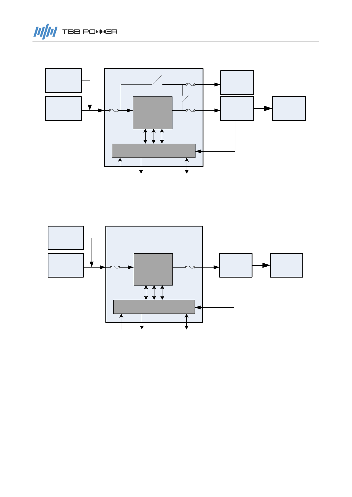
Single output DM1230 and DM1245 are the booster charger only with charge current up to 30A or
45A respectively for 12V system.
Single output DM2430 is a booster charger only with charge current up to 30Afor 24V system.
All DM and DMT chargers are Euro-6 engine compatible, which is able to charge auxiliary battery
properly and fully with much wider variable voltage output from engine.
Features
Dual outputs, separate circuits for charging battery and powering DC load (DMT1250);
Non-isolation design with max efficiency 96%;
Euro-6 engine (Smart alternator) compatible;
TBB Premium II multiple stages charging algorithm;
Multiple battery chemical for optional including lithium battery;
Built-in automatic temperature compensated charging;
Plug and Play for easy installation;
Natural cooling without fan;
Supports RS485 communication;
Protection against input/output over voltage, output over current, output short circuit, internal
over temperature, battery over temperature, battery low temperature protect for LFP etc.
Back-charging function.

Dual/single outputs booster charger
3
2.2 Topology
DC/DC
Converter
MCU
Motor
battery Auxiliary
battery
D+ LED COM
DC load
(Fridge)
Inverter
Temperature detect
Alternator
Figure 2-1 Topology of DMT models
DC/DC
Converter
MCU
Motor
battery Auxiliary
battery
D+ LED COM
Inverter
Temperature detect
Alternator
Figure 2-2 Topology of DM models
Thanks to its non-isolation design, the charging efficiency of DM/DMT is up to 96%.
When both alternator and auxiliary battery are well connected, DMT1250 will automatically judge if
engine is turning on by detecting D+ signal or sensing alternator output voltage, to decide charge
battery and power DC load by alternator, or power DC load by auxiliary battery.
All models support communication of RS485.

Dual/single outputs booster charger
4
2.3 Booster mode logic
Table2-1 Charging logic for 12V system
ACC+/D+
Term
Configuration
Starter battery voltage
Time delay
Default
Range
Default
Range
With ACC+/D+
connected
D+/ACC+ AND voltage
meets the threshold
≥13.2V
12~14.5V
20s
5~60s
Without ACC+/D+
connected
voltage meets the
threshold
≥13.2V
12~14.5V
20s
5~60s
Table2-2 Stop charging logic for 12V system
ACC+/D+
Term
Configuration
Starter battery voltage
Time delay
Default
Range
Default
Range
With ACC+/D+
connected
no D+/ACC+ OR
voltage meets the
threshold
<12.8V
11.6~13.5V
20s
5~60s
Without ACC+/D+
connected
voltage meets the
threshold
<12.8V
11.6~13.5V
20s
5~60s
Table2-3 Charging logic for 24V system
ACC+/D+
Term
Configuration
Starter battery voltage
Time delay
Default
Range
Default
Range
With ACC+/D+
connected
D+/ACC+ AND voltage
meets the threshold
≥26.4V
24~29V
20s
5~60s
Without ACC+/D+
connected
voltage meets the
threshold
≥26.4V
24~29V
20s
5~60s
Table2-4 Stop charging logic for 24V system
ACC+/D+
Term
Configuration
Starter battery voltage
Time delay
Default
Range
Default
Range
With ACC+/D+
connected,
no D+/ACC+ OR
voltage meets the
threshold
<25.6V
23.2~27V
20s
5~60s
Without ACC+/D+
connected
voltage meets the
threshold
<25.6V
23.2~27V
20s
5~60s
Remark: All above threshold voltage and time delay can be configured by Program Tool RapNEMO.

Dual/single outputs booster charger
5
2.4 TBB Premium II five stages charging algorithm
Fitted with five stages charging algorithm (soft start-bulk-absorption-float-recycle),
DMT1250/DM1230 is able to charge auxiliary battery quickly and fully. Microprocessor controlled
charging algorithm with variable absorption charging timer to guarantee the optimal charging for
batteries of different discharged states.
Float charging and Recycle charging program guarantee your battery get proper maintenance in
case of long time connected.
Battrry Voltage
Charging Current
Soft Start Bulk Absorption Float Recycle
Icc
11.5V
10 days 1h 5
mins
½ Icc
12.5V
Figure 2-3 TBB Premium II Charging Algorithm
2.5 Battery temperature compensation
Battery temperature is a key factor in correct charging, the charging formula must be adjusted
(automatically and in real time) according to the actual battery temperature to ensure that battery
are fully charged but not overcharged or undercharged. All charging voltages recommended by
battery manufacture are in fact only applied at 20℃-25℃.
The BTS (Battery Temperature Sensor) supplied with DM/DMT measures the temperature of
battery and automatically makes adjustments at real time to properly charge your batteries at the
default compensation rate of –3mv/℃/cell.
In case of BTS was not present, the charger will use 25℃as default setting.
Figure 2-4 Battery Temperature Sensor(BTS)

Dual/single outputs booster charger
6
2.6 Back-charging function
It’s required to connect D+ cable or ACC signal to enable back-charging function.
All standard models comes with back-charging function, which allows DMT/DM draws power from
auxiliary battery to charge starter battery (charge current is from 0-3A). With back-charging function,
it will prevent starter battery to get flat which fails to start engine.
Table2-5 Charging logic for 12V system
ACC/D+
Term
Starter
battery
voltage
Value Configuration
Auxiliary battery
voltage
Time delay
Default
Range
Default
Range
With ACC+/D+
connected
No ACC+/D+ is
detected AND voltage
meet the threshold
≤12.4V
≥12.2V
12.2~1
4.5V
5s
5~60s
Without
ACC+/D+
connected
without this function
Table2-6 Stop charging logic for 12V system
ACC/D+
Term
Starter
battery
voltage
Value Configuration
Auxiliary battery
voltage
Time delay
Default
Range
Default
Range
With ACC/D+
connected,
ACC+/D+ is detected
OR voltage meet the
threshold
≥12.8V
≤12V
12~14.
3V
5s
5~60s
Without
ACC+/D+
connected
without this function
Table2-7 Charging logic for 24V system
ACC/D+
Term
Starter
battery
voltage
Value Configuration
Auxiliary battery
voltage
Time delay
Default
Range
Default
Range
With ACC+/D+
connected
No ACC+/D+ is
detected AND voltage
meet the threshold
≤24.8V
≥24.4V
24.4~2
9V
5s
5~60s
Without
ACC+/D+
connected
without this function

Dual/single outputs booster charger
7
Table2-8 Stop charging logic for 24V system
ACC/D+
Term
Starter
battery
voltage
Value Configuration
Auxiliary battery
voltage
Time delay
Default
Range
Default
Range
With ACC/D+
connected,
ACC+/D+ is
detected OR
voltage meet the
threshold
≥25.6V
≤24V
24~28.6V
5s
5~60s
Without
ACC+/D+
connected
without this function
Remarks:
1. All above threshold voltage and time delay can be configured by Program Tool RapNEMO.
2. Back charging function is only available upon D+/ACC+ connected.
2.7 De-rate curve against temperature increase
DM/DMT monitors the internal temperature to decide output power. It will de-rate its output power
against temperature increasing. Below is a curve to reflect the change of output power with
temperature increase.
100%
40%
Output power percentage
25℃60℃
Ambient temperature
75℃
Figure 2-5 De-rate curve against temperature increase

Dual/single outputs booster charger
8
3. Structure and dimension
3.1 Exterior and dimension
Figure 3-1 Product front view

Dual/single outputs booster charger
9
Figure 3-2 Product dimension
3.2 Connectors and terminals
Figure 3-3 Connectors and terminals
Table 3-1 Connectors and terminals definition
No
Print
Definition
Remarks
①
Alternator
Connects to positive of Alternator
Or connects to positive of
starter battery
BAT-
Connects to negative of Alternator
Or connects to positive of
starter battery
②
Fridge/Load
Connects to positive of DC load (Fridge)
No available for DM1230
AUX BAT
Connects to positive of auxiliary battery
BAT-
Connects to negative of DC load
(Fridge) and negative of auxiliary battery
③
COM
For communication of RS485
Pin definition can be found
as below Table 3
④
D+
Connects to D+ or ACC signal at smart
alternator
BAT-
Connects to BTS' black cable
For battery temperature
sensing
Temp
Connects to BTS' white cable
V-Sen
Auxiliary battery voltage sensing
No used

Dual/single outputs booster charger
10
3.3 LED indication
Table 3-3 LED indication
No
.
Print
Color
Status
Description
1
Power
Green
ON
Working normal
OFF
No working or Low Power Mode
2
Fridge/Load
(No available
for DM1230)
Green
ON
Fridge/Load working
Flashing
Fridge/Load is over-temperature; or output to
Fridge/Load is over-current
OFF
Fridge/Load no working
3
Alternator
Green
ON
Starter battery voltage in the range
Fast
flashing
Starter battery voltage high
Slow
flashing
Auxiliary battery charges to starter battery
OFF
Starter battery voltage low
4
Charge
Green
ON
Charging battery at bulk or absorption stage
Flashing
Charging battery at float stage
OFF
No charging to auxiliary battery
5
Fault
Red
ON
1. Charger over temperature
2. Starter battery voltage high
3. Output to auxiliary battery short circuit
Flashing
1. Auxiliary battery over temperature or under
temperature
2. Fridge/Load over temperature (For DMT1250 only)
3. Output to Fridge/Load over current (ForDMT1250
only)
OFF
No fault

Dual/single outputs booster charger
11
4. Installation
4.1 Material checking
Before installation, please open the box to check if the product is broken or it’s the right item you
purchased. If you have any question, please don’t remove the package and contact us in first time.
Please check the item with the list attached in the box.
4.2 Prepare harness
The output and input cable has to be fabricated at customer end. The suggested cable specification
and counter connector could be found as below Table 4-1.
Table 4-1 Cable fabrication and counter connector
Connector
at DMT
Print
Counter connector
Cable specification
Gauge
Length
Color
Terminal
Input
connector
port
Alternator
10~16mm2
<3m
Red
M8
terminal
BAT-
10~16mm2
<3m
Black
M8
terminal
Output
connector
port
Fridge
Load
4~6mm2
<3m
Blue
(No
available
for DM
models)
AUX BAT
6~16mm2
<3m
Red
M8
terminal
BAT-
10~16mm2
<3m
Black
M8
terminal
Signal
connector
port
D+
0.3mm2
--
Blue
--
BAT-
0.3mm2
2m
Black
M8
terminal
Temp
0.3mm2
2m
White
V-Sen
No available

Dual/single outputs booster charger
12
4.3 Proper installation location
DM/DMT are designed with IP20, the installation location should be indoor.
The temperature at the house and heat sink of the charger will be as high as 60℃during its
working. So please have it installed at a location hard to touch.
Please have the installation stay away from inflammable and explosive goods.
Please have the installation stay away from kids.
Don’t install the charger based on inflammable material.
Please insure the mounting surface is solid enough for installation.
Please never install the charger into a seal enclosure with battery.
4.4 Installation space
It’s required to leave space at installation for ventilation. The dimension for ventilation is defined as
below.
≥50mm
≥50mm ≥100mm
≥50mm
Figure 4-1 The required dimension for ventilation

Dual/single outputs booster charger
13
4.5 Mounting holes
Find a appropriate mounting surface, drill mounting holes as dimension shown in below picture.
Figure 4-2 Drill holes for mounting
Please have the charger installed with auxiliary battery as close as possible to
reduce voltage drop on cable.
4.6 Auxiliary battery type and fridge load work mode setting
Table 4-2 Battery type and charge voltage
Battery type
12V battery
24V battery
Absorption
charging voltage
Float charging
voltage
Absorption
charging voltage
Float charging
voltage
AGM
(Default setting)
14.6V
13.5V
29.2V
27V
GEL
14.2V
13.8V
28.4V
27.6V
LFP
14.4V
13.5V
28.8V
27V
WET
14.8V
13.8V
29.6V
27.6V

Dual/single outputs booster charger
14
The voltage of auxiliary battery must be above 2V if the battery type isn't lithium type, or the charger
will not charge to auxiliary battery. If the auxiliary battery is lithium type and the voltage is below 2V ,
the charger works on 'wake up' mode with a constant voltage output until the output current over 3A
and then the charger turns into the battery charging mode.
Table 4-3 Fridge load working mode (For DMT1250 only)
Working mode
Description
No power to DC load
(Fridge)
DMT1250 will not power DC load (Fridge) under this mode.
Power DC load
(Fridge) only upon
driving
Under this mode:
-DMT1250 will draw power from alternator to power DC load (Fridge)
when engine is ON.
-DMT1250 will stop powering DC load (Fridge) when engine is OFF.
Power DC load
(Fridge) always
(Default setting)
Under this mode:
-DMT1250 will draw power from alternator to power DC load (Fridge)
when engine is ON.
-DMT1250 will draw power from auxiliary battery to power DC load
(Fridge) when engine is OFF.
Note:
Auxiliary battery type and DC load work mode can be configured by program tool RapNEMO.

Dual/single outputs booster charger
15
4.7 Cable connection
Figure 4-3 Connection diagram
This manual suits for next models
5
Table of contents
Other TBB power Batteries Charger manuals