TBB power Kinergier Pro Series User manual


Kinergier Pro User Manual
WARNING: HIGH VOLTAGE INSIDE
CAUTION: THE DC FUSE MUST HAVE BEENTURNED OFF BEFORE SERVICING
MADE IN CHINA

Kinergier Pro User Manual
Disclaimer
Unless specially agreed in writing, TBB Power Co.,Ltd
Take no warranty as to the accuracy, sufficiency of suitability of any technical or other
information provided in this manual or other documentation.
Assumes no responsibility or liability for loss or damage, whether direct, indirect,
consequential or incidental, which might arise out of the use of such information.
TBB offer standard warranty with its products, taking no responsibility for direct or indirect loss
due to equipment failure.
About this Manual
This manual describes our product features and provides procedure of installations. This manual
is for anyone intending to install our equipment.
General Instruction
Thanks for choosing our products and this manual were suitable for Kinergier Pro Inverter
Charger. This chapter contains important safety and operation instructions. Read and keep this
User Guide well for later reference.
The Kinergier Pro Inverter Charger needs to be installed by professionals and please pay
attention to the following points prior to installation:
Please check the input voltage or voltage of battery is same to the nominal input voltage of this
inverter.
Please connect positive terminal “+” of battery to “+” input of the inverter.
Please connect negative terminal “-” of battery to “-” input of the inverter.
Please use the shortest cable to connect and ensure the secure connection.
While connecting, please secure the connection and avoid short cut between positive
terminal and negative terminal of battery, which will cause damage of battery.
Inverter will have high voltage inside. Only authorized electrician can open the case.
The inverter WAS NOT designed to use in any life retaining equipment.

Kinergier Pro User Manual
Contents
1. General Safety Instruction .................................................................................................1
1.1 Safety instruction..............................................................................................1
1.2 General precaution...........................................................................................1
1.3 Precaution regarding battery operation ............................................................1
2. Instruction.........................................................................................................................2
2.1 Brief Instruction..................................................................................................2
2.1.1 General Description.................................................................................2
2.1.2 Naming Rules..........................................................................................2
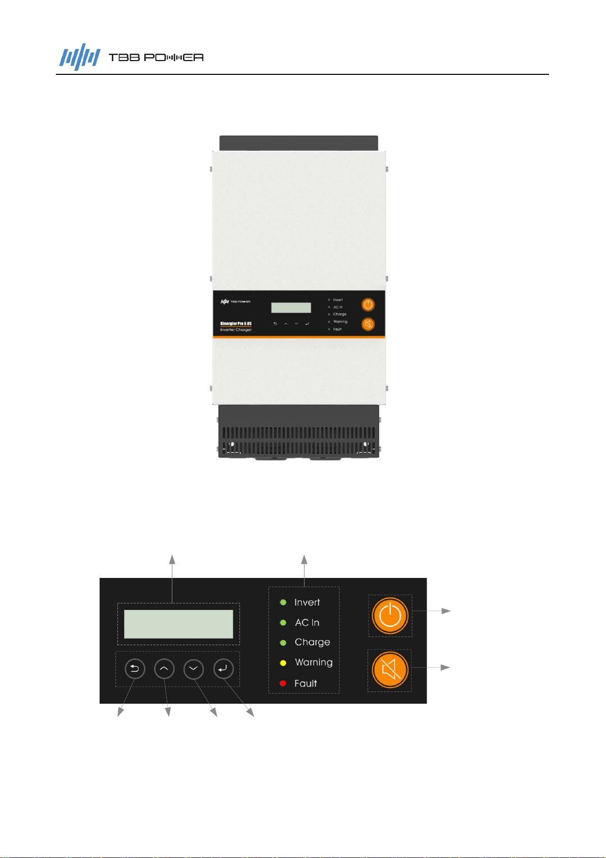
2.2 Structure ..........................................................................................................3
2.2.1 Front........................................................................................................3
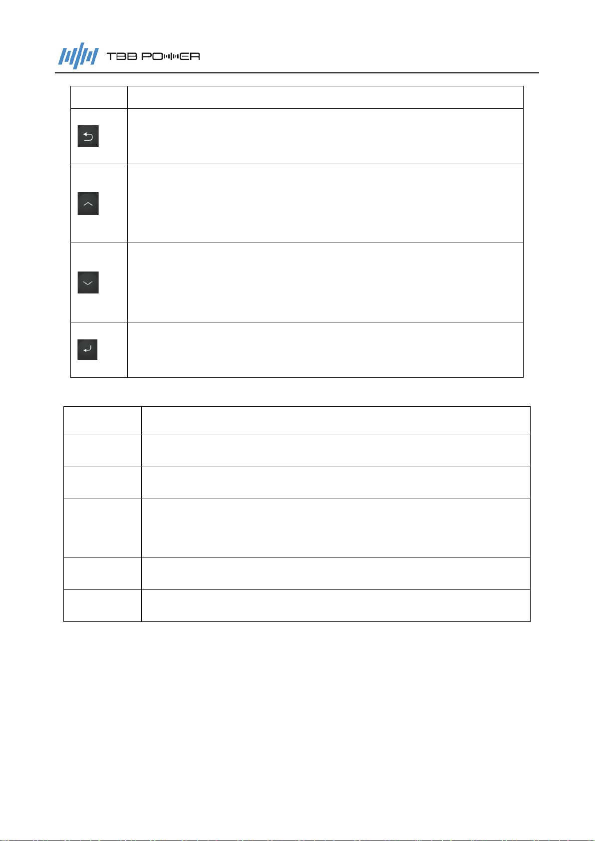
2.2.2 Control panel...........................................................................................3
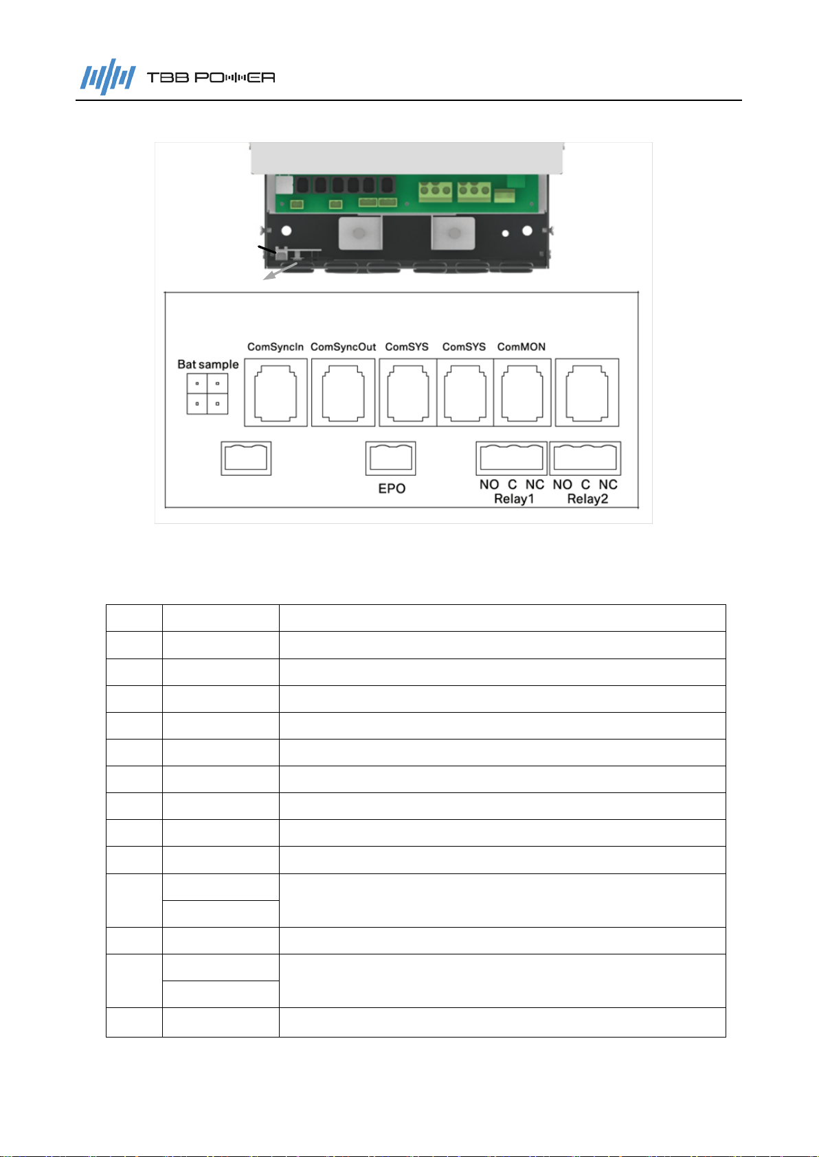
2.2.3 Connection compartment.........................................................................5
2.2.4 Dimension................................................................................................6
2.3 Function...........................................................................................................7
2.3.1 DC Couple and AC Coupled PV System..................................................7
2.3.2 Parallel and Three phase.........................................................................7
2.3.3 Power control and Power assist...............................................................7
2.3.4 System working mode .............................................................................7
2.3.5 Built-in load management........................................................................7
2.3.6 Powerful and Reliable Inverter.................................................................7
2.3.7 Professional Battery Charger...................................................................8
2.3.8 Transfer.................................................................................................10
2.3.9 Protect function......................................................................................10
2.3.10 Communication....................................................................................11
3. Installation and Wiring.....................................................................................................12
4. Configuration ..................................................................................................................13
4.1 Check before Operation...................................................................................13
4.2 Power ON Test.................................................................................................13
4.3 Power OFF......................................................................................................13
4.4 Setup Wizard...................................................................................................14

Kinergier Pro User Manual
5. Operation........................................................................................................................15
5.1 Menu introduction............................................................................................15
5.2 Initial interface..................................................................................................16
5.3 Main Menu.......................................................................................................16
5.4 Tier one menu - Information query interface.....................................................17
5.5 Tier one menu - configuration interface............................................................19
5.5.1 General operation instruction.................................................................19
5.5.2 Parameter set........................................................................................21
5.6 User control....................................................................................................30
5.6.1 ACin Logic.............................................................................................30
5.6.2 Relay Function.......................................................................................32
5.6.3 AGS Driver ............................................................................................33
5.6.4 ACout2 Logic.........................................................................................35
5.6.5 Screen Set.............................................................................................36
5.6.6 Date & Time...........................................................................................36
5.6.7 Trigger Command..................................................................................36
6. FAQ ................................................................................................................................37
6.1 Error code......................................................................................................37
6.1.1 Inverter Error .........................................................................................37
6.1.2 MPPT Error............................................................................................38
6.1.3 BMS Error..............................................................................................38
6.2 Warning code.................................................................................................39
6.2.1 Inverter Warning....................................................................................39
6.2.2 MPPT Warning ......................................................................................40
6.2.3 BMS Warning.........................................................................................41
6.2.4 BGK Warning.........................................................................................41
7. Specification ...................................................................................................................42

Kinergier Pro User Manual
1
1. General Safety Instruction
1.1 Safety instruction
As dangerous voltages and high temperature exist within the Kinergier Pro Inverter Charger, only
qualified and authorized maintenance personnel are permitted to open and repair it. Please make
sure Kinergier Pro Inverter Charger is turned off before opening and repairing it.
This manual contains information concerning the installation and operation of the Kinergier Pro
Inverter Charger. All relevant parts of the manual should be read prior to commencing the
installation. Please follow the local stipulation meantime.
Any operation against safety requirement or against design, manufacture, safety standard are out
of the manufacturer warranty.
1.2 General precaution
DO NOT expose to dust, rain, snow or liquids of any type. It is designed for indoor use. DO
NOT block off ventilation, otherwise the Kinergier Pro Inverter Charger would be
overheating.
To avoid fire and electric shock, make sure all cables selected with right gauge and being
connected well. Smaller diameter and broken cable are not allowed to use.
Please do not put any inflammable goods near to inverter.
NEVER place unit directly above batteries because gases from a battery will corrode and
damage Kinergier Pro Inverter Charger.
DO NOT place battery over Kinergier Pro Inverter Charger.
1.3 Precaution regarding battery operation
Use plenty of fresh water to clean in case battery acid contacts skin, clothing, or eyes and
consult with doctor as soon as possible.
The battery may generate flammable gas during charging. NEVER smoke or allow a spark
or flame in vicinity of battery.
DO NOT put the metal tool on the battery because spark and short circuit might lead to
explosion.
REMOVE all personal metal items such as rings, bracelets, necklaces, and watches while
working with batteries. Batteries can cause high enough short-circuit current to make metal
melt, and could cause severe burns.

Kinergier Pro User Manual
2
2. Instruction
2.1 Brief Instruction
2.1.1 General Description
Kinergier Pro is the new generation inverter charger designed for various type of off grid system
including AC Coupled PV System, DC Coupled PV System and generator hybrid system. It can
provide UPS class switching speed and capability to support parallel as well as composing three
phase system.
Kinergier Pro delivers high reliability, performance and industry leading efficiency for mission
critical application. Its distinguishing surge capability makes it capable to power most demanding
appliances, such as air conditioner, water pump, washing machine, freezer etc.
With the function of power assist & power control, it can be used to work with a limited AC source
such as generator or limited grid. Kinergier Pro can automatically adjust its charging current to
avoid grid or generator to be overloaded. In case of temporary peak power appears, it can work as
a supplement source to generator or grid.
2.1.2 Naming Rules
Rated capacity
Rated DC voltage
Series name
CK XX Y ZZ
Rated AC voltage
figure explanation
CK series name
3.0
Represent rated capacity
3000W
4.0 4000W
5.0 5000W
6.0 6000W
8.0 8000W
M Represent rated DC voltage 24VDC
S 48VDC
-- Represent rated AC voltage 230VAC
Naming example : CK8.0S
Kinergier Pro Inverter Charger
Rated capacity : 8000W
Rated dc voltage : 48V

Kinergier Pro User Manual
3
2.2 Structure
2.2.1 Front
Figure 2-1 Inverter Charger structure in front view
2.2.2 Control panel
LCD LED
ON/OFF
MUTE
&
Unlock the fault
and alarm
Cancel/Back Page up Page down Enter
LCD Operation Button
Figure 2-2 Inverter Charger control buttons

Kinergier Pro User Manual
4
Table 2-1 Control Buttons
Button Function
Cancel the selection.
Display the previous level of menu.
Display the previous page.
Increase the value of the selected item.
Press the button for more than 2 seconds to scroll the page up.
Display the next page.
Decrease the value of the selected item.
Press the button for more than 2 seconds to scroll the page down.
Enter into this menu, displaying the next level.
Select and confirm the selection of a menu item.
Table 2-2 LED directive function
LED Function
Invert It will illuminate when CK is inverting.
AC In It will flash when CK detect any input, mains or generator.
Charge It will flash when CK is in float charging.
It will illuminate when CK is in bulk or absorption charging.
Warning It will flash when CK have warning.
Fault It will flash when CK have error.

Kinergier Pro User Manual
5
2.2.3 Connection compartment
A
B
C
H
G
FE
D
I
J
K
L
M
Remote
ComMON
Inverter Charger signal terminal definition
Figure 2-3 Signal terminal
Table 2-3 Signal terminal introduction
No. Silk-screen Definition
A Bat Sample Battery temperature and voltage sample.
B Remote Dry contact input control, remote ON/OFF control.
C Com MON Connected to the connector K by default.
D WCM Connected to the Kinergy data logging stick.
E Com Sync In Parallel synchronous communication input(CAN) .
F Com Sync Out Parallel synchronous communication output(CAN) .
G EPO Dry contact input control, emergency power off.
H Com SYS System communication(RS485), connected to SP or BGK.
I Com SYS System communication(RS485), connected to SP or BGK.
J Relay1 Dry contact output control 1(NO,C,NC) .
(NO,C,NC)
K Com MON Connected to connector C by default.
L Relay2 Dry contact output control 2(NO,C,NC) .
(NO,C,NC)
M Com MON RS485 port for external monitor such as MCK, SNMP etc.

Kinergier Pro User Manual
6
Figure 2-4 Power terminal
2.2.4 Dimension
Figure 2-5 Dimension of Inverter Charger
(CK4.0M,CK5.0M,CK4.0S,CK5.0S,CK6.0S,CK8.0S)

Kinergier Pro User Manual
7
2.3 Function
2.3.1 DC Couple and AC Coupled PV System
Using Kinergier Pro together with Solar Max MPPT and PV inverter from TBB Power, you can
compose both DC Coupled PV System and AC Coupled PV System. Featuring greater flexibility,
AC Coupled PV System can achieve higher system power and is much more suitable for
commercial project. Please refer to 5.5.2.1 for explanation in details.
It is recommended to use IG series PV inverter from TBB Power to compose AC Coupled PV
System. In case you want to use third party PV inverter, please consult with TBB Power sales.
2.3.2 Parallel and Three phase
Two or more units can be connected in parallel to compose a single-phase parallel system or a
three-phase parallel system, which is convenient for system expansion or to construct a
micro-grid system. For single phase system, max three units can be connected in parallel. For
three phase system, max 9 units can be connected in together.
2.3.3 Power control and Power assist
Kinergier Pro offers an unique feature of power control & power assist, which is very useful upon
you have a limited grid supply or working with generator. Kinergier Pro will take control of energy
flow automatically, using extra power to charge the battery or inverting as the supplement to the
grid or generator. With this feature, you can avoid tripping of shore power MCB or generator
oversize.
2.3.4 System working mode
Kinergier Pro offers powerful functions for user to program for different systems, such as power
backup, solar hybrid, ESS, ESS with peak tariff shaving etc. Please refer to the chapter 5.6.1 for
details.
2.3.5 Built-in load management
There are two outputs built-in Kinergier Pro. AC output 1 is used to connect critical loads which
will be backed up with battery connected. AC OUT2 is the secondary outputs and you can
configure it with different functions, such as grid only, base on specific time zone or specific
battery voltage or SOC. Please refer to the chapter 5.6.4 for details.
2.3.6 Powerful and Reliable Inverter
High performance pure sine wave
Kinergier Pro is a pure sine wave inverter generating a near perfect sinusoidal AC wave power
output that is very similar or even better to what you can get from your utility grid. Pure sine wave
can guarantee the correct function of sensitive equipment (computer, laser printer, TV etc.). Also,
your home appliances will work smoother, cooler and more efficient, such as fridge, microwave
and power tools.
High surge power capability
Provided with outstanding surge power capability and low frequency transformer, Kinergier Pro is

Kinergier Pro User Manual
8
suitable for heavy inductive loads like fridge, coffee maker, microwave, power tools, air conditioner,
etc.
Battery low voltage protect
Kinergier Pro provides configurable battery low voltage protection.
2.3.7 Professional Battery Charger
Multi stage sophisticated charging algorithm for lead acid battery
Fitted with multistage charging algorithm (bulk-absorption-float-recycle), the built-in charger of
Kinergier Pro is designed to charge battery quickly and fully. Microprocessor controlled charging
algorithm with variable absorption charging timer could guarantee the optimal charging for
batteries of different discharged state.
Battery Voltage
Charge Current
Soft Start Bulk Absorption Float Recycle
Icc
11.5V
10 days 1h 5
mins
½ Icc
Figure 2-6 Multi stage sophisticated charging algorithm for lead acid battery
Float charging and recycle charging program guarantee your battery getting proper maintenance
in case of long time connected and less aging in case of long time connected with no use.
Battery Sample Cable (Temperature and voltage)
Battery temperature is a key factor in correct charging for lead acid battery, the charging formula
must be adjusted (automatically and in real time) according to the actual battery temperature to
ensure that battery are fully charged but not overcharged or undercharged. All charging voltages
recommended by battery manufacture are in fact ONLY applied at 20℃-25℃.
The Bat sample cable (battery temperature and voltage sensor) supplied with Kinergier Pro
measures the temperature of battery and automatically makes adjustments at real time to properly
charge your batteries at compensation rate of – 4mV/℃/cell. In case of Bat sam ple cable is not
available, Kinergier Pro will use 25℃as default setting. This feature is especially recommended
for sealed batteries and/or when important fluctuations of battery temperature are expected.
Multi battery chemical available

Kinergier Pro User Manual
9
Kinergier Pro offers premium charging algorithm for commonly encountered lead acid battery
chemicals including AGM, GEL, Flooded, lead-carbon and Lithium battery which you can set
through LCD interface and TBB Link software.
Lithium Battery Compatible
Kinergier Pro has built-in communication compatible with for Super L lithium battery from TBB.
Manual Equalization
It is strongly recommended to read this section carefully before you start the EQ
charging and don’t leave battery unattended while performing desulfuration.
Always check if your battery supplier recommended EQ charging. Only start when it
is suitable.
If battery type was set at AGM, GEL or Lead-Carbon, this charging profile can’t be
triggered on.
Over a period of time, the cells in a flooded battery can develop uneven chemical states. This will
result in a weak cell which in turn can reduce the overall capacity of battery. To improve the life
and performance of flooded battery, Kinergier Pro includes a manual equalization program that
can be used, if recommended by battery manufacturer. You can initiate the desulfuration program
manually. Once you trigger on the equalization program, Kinergier Pro will perform equalization
charging.
After 30 minutes, it will quit EQ and enter into float charge.
Check electrolyte level and refill battery with distilled water if necessary.
If you want to come to normal charging, you need stop equalization charging and switch off
the unit.
Switch on the unit again, then you will have your equipment back to normal charging.
During equalization, the battery generates potentially flammable gases. Follow all
the battery safety precautions listed in this guide. Ventilate the area around the
battery thoroughly and ensure that there are no sources of flame or sparks in the
vicinity.
Turn off or disconnect all loads on the battery during equalization. The voltage
applied to the battery during equalization may be above the safe levels for some
loads.
Frequency:
Maximum once a month, for heavily used battery, you may wish to equalize your battery. For
battery with light service only need to be equalized every 2-3 months.
Important:
Equalization can damage your batteries if it is not performed properly. Always check battery
fluid before and after equalization. Fill batteries only with distilled water.
Always check the equalization switch is set back to OFF after each time’s equalization.

Kinergier Pro User Manual
10
Battery manufactures’ recommendations on equalization vary. Always follow the battery
manufacturer’s instructions so batteries can be properly equalized. As a guide, a heavily used
battery may require equalization once a month while a battery in light duty service, only needs
equalizing once every 2 to 4 months.
Battery type:as a protection, equalization charging can be performed if and only if you set the
battery to be traction, Flooded /OPzS batteries. If you choose AGM, GEL or Lead-Carbon, EQ
charging can’t be performed.
2.3.8 Transfer
Uninterrupted AC power
In case of voltage/frequency/waveform of AC input match the minimum quality, the voltage will be
switched directly to AC output. Kinergier Pro Inverter Charger will work as a battery charger and
load will be powered by AC input. You will have the same voltage both at the output and AC input.
In case of AC input failure or exceeding the maximum AC input current set by the user, Kinergier
Pro Inverter Charger will initiate a quick switching to inverter, which will guarantee an undisturbed
power. Upon AC input resume or match the quality, it will switch back again. Due to its ultra quick
transfer design, as quick as 0ms, Kinergier Pro Inverter Charger could be used as an UPS.
Ground Relay
The neutral output of Kinergier Pro Inverter Charger is automatically connected to earth upon
no external AC sources is available. Once external AC sources is available, the ground relay will
open. You can disable this feature through TBB Link.
L
N
PE
AC out1
EMI
FILTER
PE
AC in
L
N
AC out2
L
N
PE
Ground relay
Figure 2-7 Ground Relay Schematic
2.3.9 Protect function
The Kinergier Pro Inverter Charger is equipped with a series of complete hardware and software
protection functions to ensure its stable and reliable operation.
Overload protection
When overload protection is triggered on, it will restart automatically after 60s. And after three
consecutive overload shutdown protections, the equipment will not restart automatically. At this
time, the user needs to manually restart it.

Kinergier Pro User Manual
11
Over temperature protection
When the internal temperature is too high, Kinergier Pro will enter into the over-temperature
protection. After the internal temperature returns to normal, it can automatically resume normal
operation.
Short circuit protection
The equipment will automatically shut down when the AC output is shorted and needs to be
manually activated.
Battery over temperature protection
During the charging, the equipment will continuously monitor the battery temperature. When the
battery temperature is too high, the equipment will automatically reduce the charging current.
When the battery is severely heated, the charger will automatically turn off to protect the battery.
Battery low voltage protection
To prevent the permanent damage caused by the over discharge of battery, the equipment will
automatically cut off the output according to the low voltage protection point set by the user.
2.3.10 Communication
Dry contact input
Kinergier Pro is equipped with two dry contact inputs for remote on/off and EPO control.
Dry contact output
Kinergier Pro is equipped with two NO/NC relay type dry contact outputs, the user can set specific
functions through the LCD. Below is the default setting.
Relay1: The relay is closed when the battery is under voltage.
Relya2: The relay is closed when a fault or overload occurs.
RS485
Equipped with two RS485 interfaces.
CAN
Equipped with a CAN interface.

Kinergier Pro User Manual
12
3. Installation and Wiring
Please refer to "Quick Installation Guide".
Keep away from fire, avoid direct sunlight and rain; do not store flammable,
explosive or corrosive gases or liquids in the working environment. Don't
install in a working environment with metal conductive dust.
Please install the equipment in a location of dry, clean, cool with good ventilation.
Operating temperature: -20~65℃
Storage temperature: -40~70℃
Cooling: Force fan
Relative humidity in operation: 95% without condensation.

Kinergier Pro User Manual
13
4. Configuration
4.1 Check before Operation
Please check before operation according to the following.
Inverter is installed correctly and steady.
Reasonable cable layout to meet customer requirements.
Make sure the grounding is reliable.
Make sure the ground wire is properly connected and firm and reliable.
Double check the battery breaker is OFF.
Make sure the cables are properly connected, firm and reliable.
Reasonable installation space, clean and tidy environment, no construction residue.
4.2 Power ON Test
Make sure the battery voltage is within the permissible range before turning
ON the breaker.
Please follow the following instruction step by step.
Step 1: Turn on the circuit breaker between the battery and the inverter.
Step 2: Press the On/Off button to turn on the inverter to enter self diagnostic.
Step 3: Set the parameters following the setup wizard.
Step 4: Press the On/Off button again to turn on the inverter.
Step 5: Observe the LED light to make sure the inverter is running normally.
(refer to Tab 2-2 LED directive function)
4.3 Power OFF
After the inverter is power OFF, there is still residual power and heat in the
chassis, which may lead to electric shock or burn. Therefore, after the
MPPT charger is powered off for 5 minutes, you should wear protective
gloves before removing the MPPT charger.
Method 1: Press the On/Off button about 2secs to turn off the output of inverter. Afterwards,
you can press and hold the On/Off for 5secs, after hearing consecutive beep, you can
permanently shut down the inverter.
Method 2: Press and hold the On/Off for 5secs, after hearing consecutive beep, you can
permanently shut down the inverter straight away.

Kinergier Pro User Manual
14
4.4 Setup Wizard
For the purpose of a quick configuration, upon turning on Kinergier Pro for the first time or after
restoring the factory settings, the equipment will enter the setup wizard automatically covering all
basic setting you need to perform.
Please refer to 5.5.2 for detailed explanation for each parameter.
Battery_Type
0-GEL/OPzV /1-AGM ...
Battery_AH
xxxxAH
INV_Output_VOLT
230V /240V /220V
INV_Output_FREQ
50Hz /60Hz
Parallel_System
0-Stand-alone /1-Parallel /2-Three-Phase
Parallel_UVW
1-Phase-U(L1)
2-Phase-V (L2)
3-Phase-W (L3)
Parallel_Addr
1 /2 /3
if Parallel_System == 2
if Parallel_System == 1
Solar_System
0-N/A /1-DC Couple /2-AC Couple/3-DC+AC Couple
MPPT_CHG_Num
1~6
PV_Inverter_Num
1~2
If Solar_System == 2 or 3
If Solar_System == 1 or 3
ACin_Source_SEL
0-Grid /1-Gen
If Solar_SYS_Set == 0
if Parallel_System == 0
ACin_Limit_Cur
50A(Power Assist)
if Common_N_Line== 0
Wait Master Set
Finish...
Synchronize Master Para?
if judged to be slave
Time Set
2019-03-10 13:26
If Battery_Type == 6
Turn To Home Page
Please Wait....
Enter The
Setup Wizard?
BGK_Module
0-N/A /1-BGK-12 /2-BGK-Balancer
Ground Relay
0-Disable /1-En
Common_N_Line
0-Disable /1-En
if Common_N_Line== 1

Kinergier Pro User Manual
15
5. Operation
5.1 Menu introduction
There will be a main menu and three tiers of menus on LCD showing all active parameters and
alarms for you to configure all parameters of Kinergier Pro.
TBB Power
MCU complete initialization
Kinergier Pro
MCU turn on
&Establish communication
with the inverter
&Get the Type
2018-07-20 13:26
Inverter On
U_BAT 54.3V
I_DisCHG 115A
U_INV 228V
P_INV 5120W
<Enter>
>Running Data
<Enter>
>Statistic Data
<Enter>
>Current Error
>History Record
<Enter>
Inverter Err: 02
Vbus_LV
Inverter Warn:06
NTC_TX_Fault
MPPT 1# Err: 02
Vbat_LV
MPPT 1# Warn: 06
T_BatExt_OT
……
cycle display in normal state
<Back>
<Back>
<Back>
MPPT 1# Warn: 20
Comm Offline
<Enter>
<Back>
<Enter>
<Back>
>Parameter Set
<Enter>
<Back>
<Enter>
<Back>
……
>Factory Set
<Enter>
<Back>
LCD self-test
animation, backlight
<Down>
<Down>
<Down>
<Down>
<Up>
<Up>
<Up>
<Up><Down>
<Back>
<Up>
>System Info
<Enter>
<Back>
<Up><Down>
U_ACin 1005W
P_ACin -5100W
>User Control
<Up><Down>
<Enter>
<Back>
<Enter>
<Back>
E_ACout_Consume:
0.9kWh
E_ACin_Consume:
3.9kWh
E_ACin_Feedback:
1.2KWh
0 error
0 warning
2019-03-02 10:30
MPPT 1# Warn: 20
>Para_System
Para_Mode
>Model
Serial Number
>Software Ver
Firmware Ver
>Para_Inverter
Para_Battery
Para_ACin
>Change Password
>ACin Logic
Relay Logic
>Factory System
Factory Sample
>Para Set Log
Clear Log
>ACout2 Logic
AGS Logic
>Hardware Ver
>Factory Debug
Reset Password
2018-03-01 21:37
Inverter Err: 06
……
E_INV_Discharge:
3.2KWh
……
2018-03-01 05:30
MPPT 1# Err: 13
2018-03-01 03:26
Inverter On
MPPT 1# Err: 13
EPO
<Enter>
<Back>
2018-03-02 13:26
MPPT 1# Online
<Enter>
<Back>
……
<Enter>
<Back>
……
>Screen Set
Date & Time
……
Setup Wized
>Reset Parameter
>Reset Device
>Trigger Command
……
MPPT 1# Warn: 20
Comm Offline
……
P-ACin 1005W
P-ACout 500W
PF-load 0.91
S-ACout 550VA
U-INV 228V
P-INV -500W
……
Priority alarm when a fault occurs
Initial interface Main menu Tier one menu Tier two menu Tier three menu
Note: When the system is set up with MPPT
communication monitoring, MPPT related
information and settings will be displayed.
This manual suits for next models
6
Table of contents
Other TBB power Batteries Charger manuals