manuals.online logo
Brands
  1. Home
  2. •
  3. Brands
  4. •
  5. TE Connectivity
  6. •
  7. Cables And Connectors
  8. •
  9. TE Connectivity VAL-U-LOK 3-1586040-6 User manual

TE Connectivity VAL-U-LOK 3-1586040-6 User manual

©2013 Tyco Electronics Corporation, a TE Connectivity Ltd. company
All Rights Reserved
*Trademark
TE Connectivity, TE connectivity (logo), and TE (logo) are trademarks. Other logos, product and/or company names may be trademarks of their respective owners.
1of 2
Instruction Sheet
TOOLING ASSISTANCE CENTER
1-800-722-1111
PRODUCT INFORMATION
1-800-522-6752
This controlled document is subject to change.
For latest revision and Regional Customer Service,
visit our website at www.te.com
408-32113
VAL-U-LOK* Connector System
with Terminal Position Assurance 18 OCT 13 Rev A
Figure 1
1. INTRODUCTION
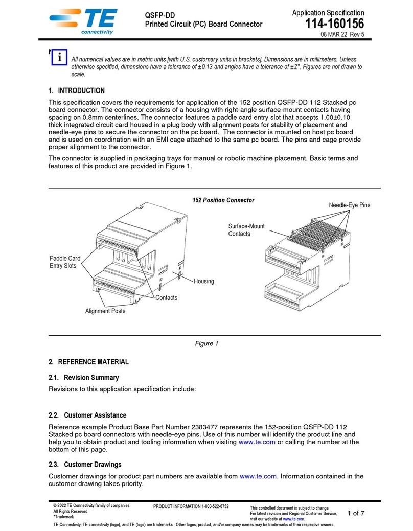
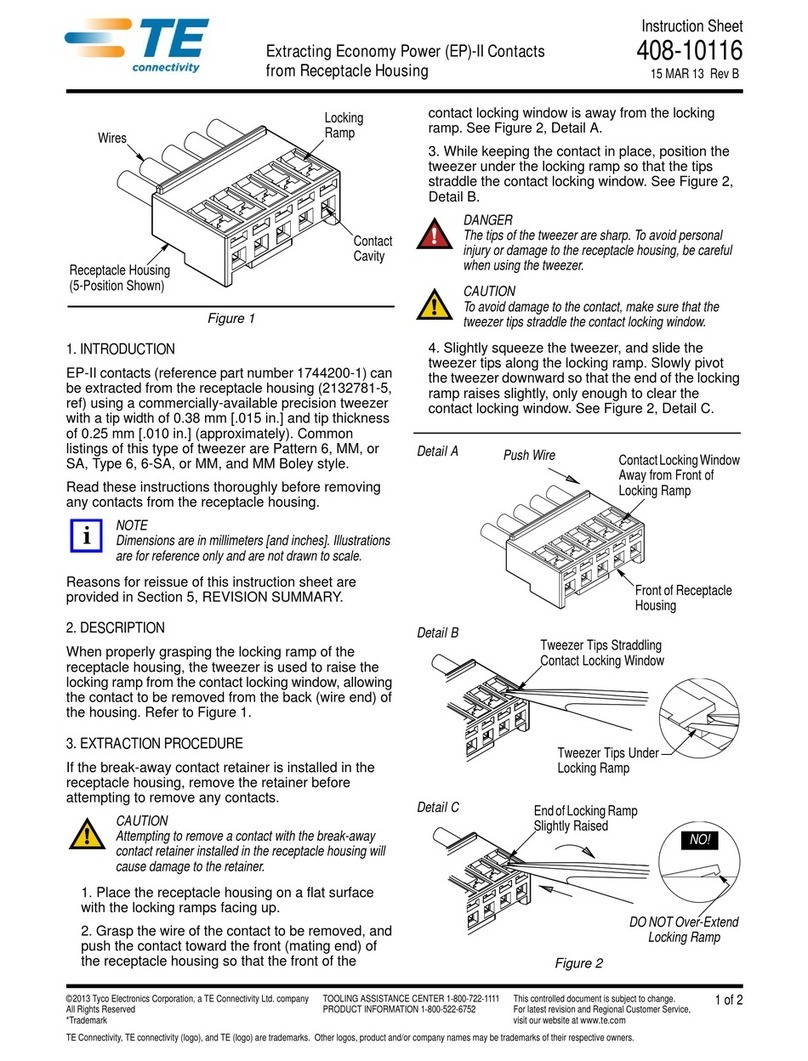
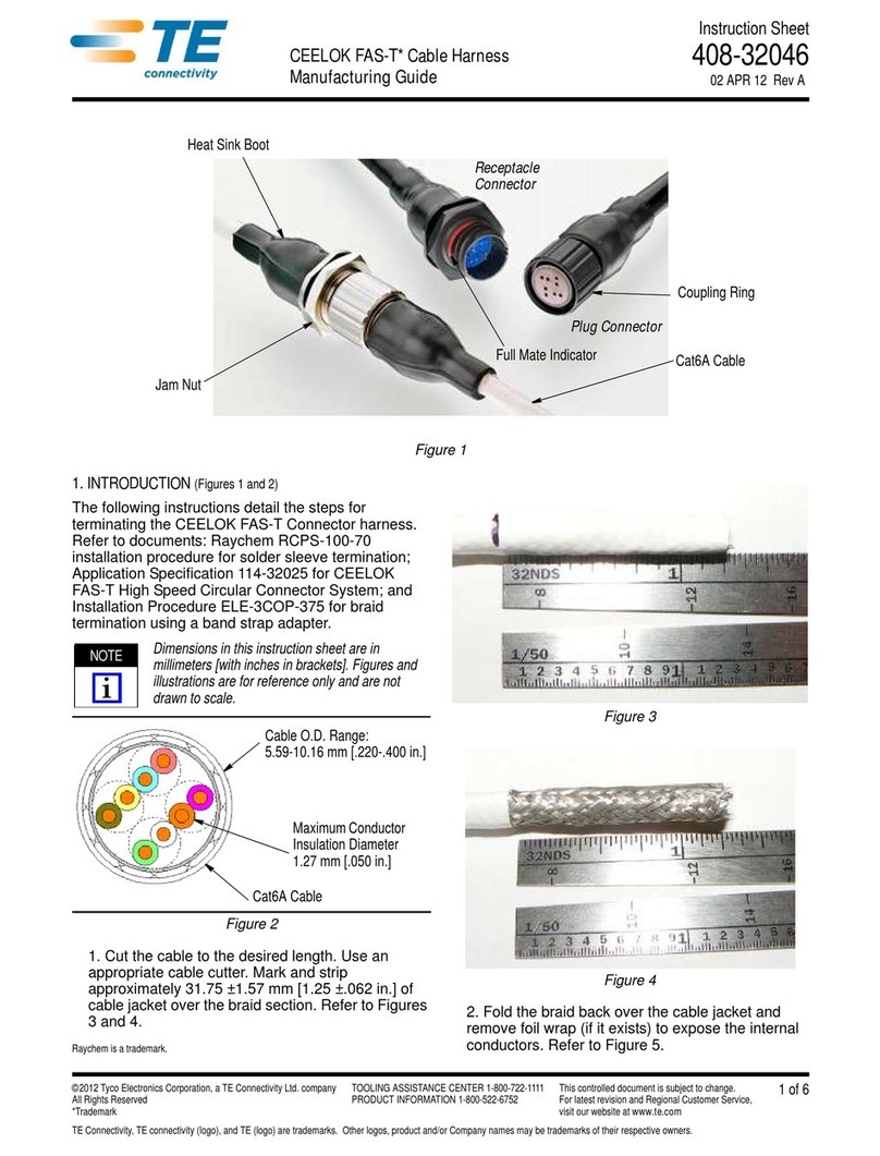
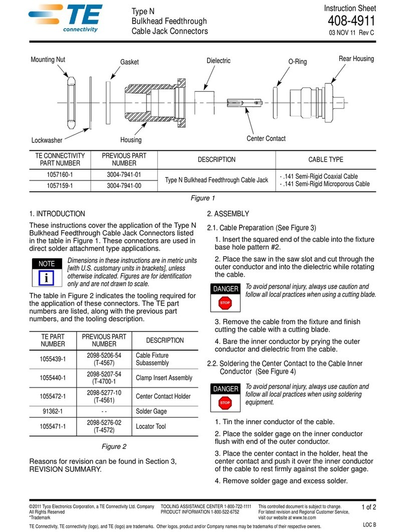
This instruction sheet covers assembling a terminated
contact, housing and TPA as represented in Figure 1
and extracting the contacts from the housing.
Reasons for reissue of this instruction sheet are
provided in Section 6, REVISION SUMMARY.
NOTE
Dimensionsin theseinstructions arein metricunits [with
inches in brackets]. Figures and illustrations are for
reference only and are not drawn to scale.
2. DESCRIPTION
All VAL-U-LOK pin and socket contacts have two
flexible latches that lock into their respective housings
when fully inserted. The TPA-compatible contacts
have special features on their insulation barrels that
work in conjunction with the TPA device to ensure full
contact insertion. See Figure 2A.
The plug and receptacle housings are available in 2
through 24 positions which are arranged into 2 rows.
The TPA devices are available in 1 through 12
positions, single row, so 2 TPA devices are required
for each housing. The TPA is designed to be installed
into the housing to ensure all contacts are fully
inserted and will not back out during mating. When
fully installed, the locking latches of the TPA snap onto
raised ledges around the perimeter of the housing.
See Figure 3B.
3. ASSEMBLY
1. Ensure that the contact is properly terminated to
the wire according to the requirements provided in
Application Specification 114-13172. Check that the
flexible latches are not damaged or distorted from
their original form as shown in Figure 2A.
2. Insert the terminated contact into its respective
housing as follows:
a. Grasp the contact directly behind the
insulation barrel. Align the contact with a contact
cavity in the housing at the wire entry end as
shown in Figure 2A. Make sure that the contact is
perfectly aligned (not angled or rotated) to the
contact cavity. See Figure 2B.
Figure 2
Terminated Contact Housing
TPA
NOTE
i
2A
2B
SpecialFeatures on
Insulation Barrel
Flexible
Latches
Contact Perfectly Aligned
Angled or Rotated Entry Not Acceptable

408-32113
2of 2
Rev A
CAUTION
Never insert the contact upside down; otherwise, the
locking latches could depress and lodge into the cavity
in an unseated position or become compressed so that
they will not lock when repositioned for proper insertion.
b. Push the contact straight, not rotated, into the
contact cavity. If it is rotated, damage to the
contact will occur or the contact will not latch
properly into the contact cavity. See Figure 2B.
Do not force the contact into the housing. It
should slide in and latch into position with
minimal force.
c. Ensure that the contact latches are locked into
the cavity by pulling lightly on the wire and
checking for resistance to pull out.
3. Install the TPAs into the housing as follows:
a. Align a TPA with the wire end of the housing
so that each tooth faces a contact cavity with its
radius surface against the wire. See Figure 3A.
b. Slide the TPA into the housing so that the
teeth enter the contact cavities evenly and until
all the locking latches lock onto the ledges
around the perimeter of the housing. Make sure
to push on each locking latch individually to
ensure complete installation. There will be an
audible and tactile “click”. See Figure 3B.
NOTE
TPAs with more than 5 positions have 4 locking latches.
TPAs with 5 positions or less have only 2 locking
latches. Make sure to push on each locking latch
individually to ensure complete installation.
c. Flip the housing over and repeat steps “3a”
and “3b” with a second TPA for the other row.
4. EXTRACTING CONTACTS
1. TPAs can be removed from the housing by
releasing the locking latches from the ledges and
pulling the TPA straight away from the housing. No
contact can be extracted until the TPA is removed.
2. Contacts can be removed from housings using
Extraction Tool 1586343-1 according to Instruction
Sheet 408-32114.
CAUTION
DO NOT re-insert any extracted contacts.
5. REPLACEMENT AND REPAIR
•DO NOT use defective or damaged products.
Contacts, housings, and TPAs are not repairable.
•DO NOT re-use a contact by removing the wire.
•DO NOT re-insert any contact after extracting it
from the receptacle housing.
6. REVISION SUMMARY
•Initial release of document
Figure 3
!
NOTE
i
!
3A 3B
Align TPA with Teeth
Facing Contact
Cavities
Place Radiused
Surfaces of Teeth
Against the Wires
Ledge Around
Perimeter of Housing Latch Fully
Engaged
Onto Ledge

This manual suits for next models

2

Other TE Connectivity Cables And Connectors manuals

TE Connectivity M12 User guide

TE Connectivity

TE Connectivity M12 User guide

TE Connectivity QSFP-DD User guide

TE Connectivity

TE Connectivity QSFP-DD User guide

TE Connectivity CEELOK FAS-T User manual

TE Connectivity

TE Connectivity CEELOK FAS-T User manual

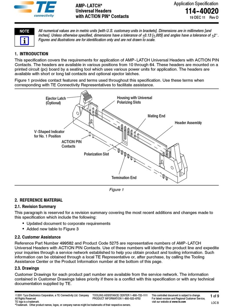
TE Connectivity AMP-LATCH User guide

TE Connectivity

TE Connectivity AMP-LATCH User guide

TE Connectivity MATE-N-LOK 2 794216-1 User manual

TE Connectivity

TE Connectivity MATE-N-LOK 2 794216-1 User manual

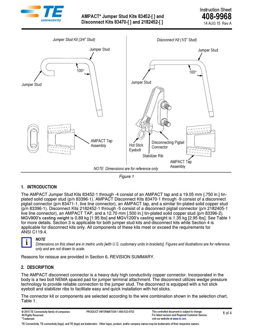
TE Connectivity 747564-9 User manual

TE Connectivity

TE Connectivity 747564-9 User manual

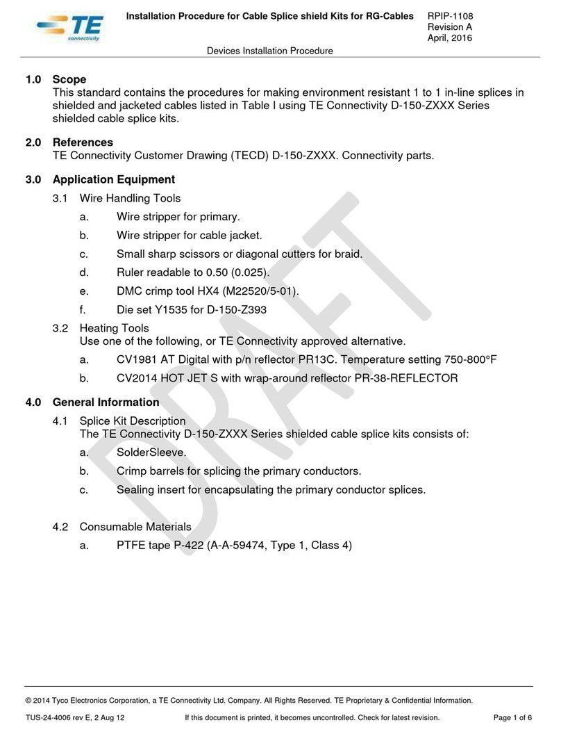
TE Connectivity D-150-Z Series Reference guide

TE Connectivity

TE Connectivity D-150-Z Series Reference guide

TE Connectivity HVA630-2phm User manual

TE Connectivity

TE Connectivity HVA630-2phm User manual

TE Connectivity HV-CP User manual

TE Connectivity

TE Connectivity HV-CP User manual

TE Connectivity EP-II User manual

TE Connectivity

TE Connectivity EP-II User manual

TE Connectivity CCS1 User manual

TE Connectivity

TE Connectivity CCS1 User manual

TE Connectivity 025/250 User manual

TE Connectivity

TE Connectivity 025/250 User manual

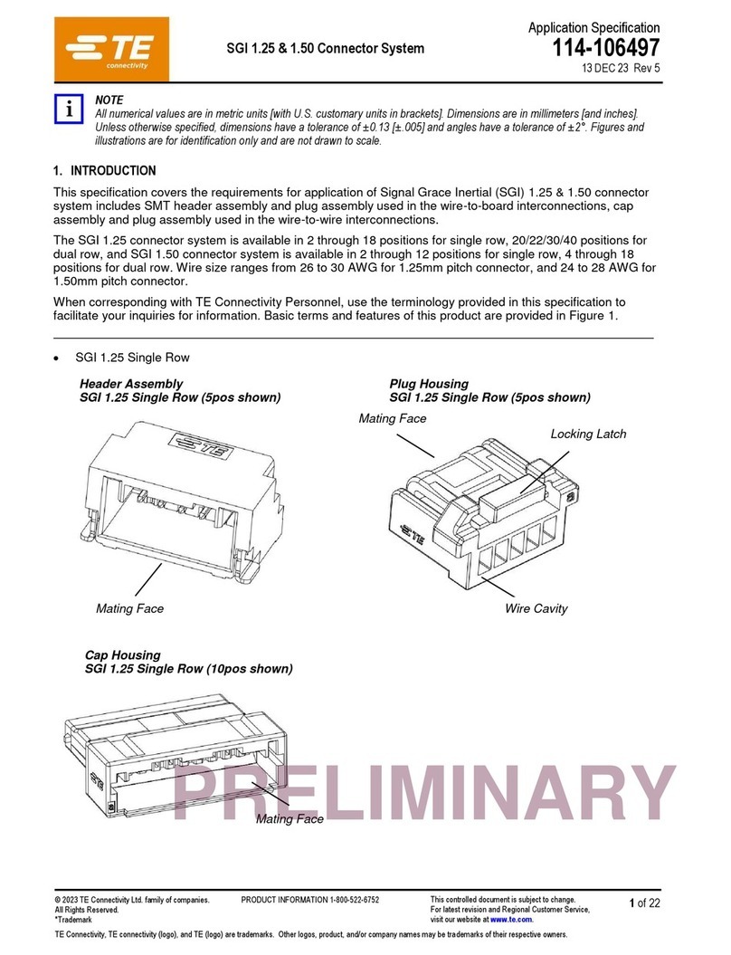
TE Connectivity SGI 1.25 User guide

TE Connectivity

TE Connectivity SGI 1.25 User guide

TE Connectivity AMP NETCONNECT 1499119-1 User manual

TE Connectivity

TE Connectivity AMP NETCONNECT 1499119-1 User manual

TE Connectivity RF COAXIAL User manual

TE Connectivity

TE Connectivity RF COAXIAL User manual

TE Connectivity AMPLIMITE HDP-20 User manual

TE Connectivity

TE Connectivity AMPLIMITE HDP-20 User manual

TE Connectivity DRC16 User manual

TE Connectivity

TE Connectivity DRC16 User manual

TE Connectivity HVP800 2PHI 90 User manual

TE Connectivity

TE Connectivity HVP800 2PHI 90 User manual

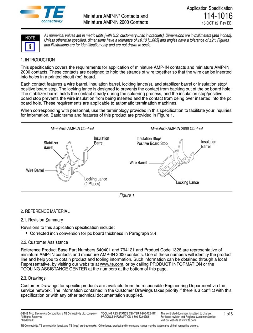
TE Connectivity Miniature AMP-IN User guide

TE Connectivity

TE Connectivity Miniature AMP-IN User guide

TE Connectivity LJSU-4X Series User manual

TE Connectivity

TE Connectivity LJSU-4X Series User manual

TE Connectivity GS-IPC-500U User manual

TE Connectivity

TE Connectivity GS-IPC-500U User manual

TE Connectivity RAYCHEM D-436 Series Reference guide

TE Connectivity

TE Connectivity RAYCHEM D-436 Series Reference guide

TE Connectivity SolderSleeve CWT Series Reference guide

TE Connectivity

TE Connectivity SolderSleeve CWT Series Reference guide

TE Connectivity HVA630-5p User manual

TE Connectivity

TE Connectivity HVA630-5p User manual

Popular Cables And Connectors manuals by other brands

AVARRO 0E-HDMISP4 manual

AVARRO

AVARRO 0E-HDMISP4 manual

Monoprice HD-140E3-3D-V2 manual

Monoprice

Monoprice HD-140E3-3D-V2 manual

Crestron CBL-USB-RS232KM-6 installation guide

Crestron

Crestron CBL-USB-RS232KM-6 installation guide

Philips Sonicare 300 SerieS user manual

Philips

Philips Sonicare 300 SerieS user manual

GoMax Electronics SP-5018KP user manual

GoMax Electronics

GoMax Electronics SP-5018KP user manual

Gefen DVI-144 user manual

Gefen

Gefen DVI-144 user manual

Sitecom PRO LINE CA-1003 user manual

Sitecom

Sitecom PRO LINE CA-1003 user manual

AAVARA PS124 installation guide

AAVARA

AAVARA PS124 installation guide

Anritsu S110-1-R instruction sheet

Anritsu

Anritsu S110-1-R instruction sheet

Chauvet Professional RDMX Splitter 8 Quick reference guide

Chauvet Professional

Chauvet Professional RDMX Splitter 8 Quick reference guide

Comtest Advanced Networks Splitter Shelf 2144 installation guide

Comtest Advanced Networks

Comtest Advanced Networks Splitter Shelf 2144 installation guide

Kramer WP-211DS user manual

Kramer

Kramer WP-211DS user manual

Sony RC-202iPV instructions

Sony

Sony RC-202iPV instructions

3M ECAM-20 MM-D instructions

3M

3M ECAM-20 MM-D instructions

Binary B-220-HDSPLTR-1X8 owner's manual

Binary

Binary B-220-HDSPLTR-1X8 owner's manual

Ask HDSP0102N user manual

Ask

Ask HDSP0102N user manual

Eaton 600 A 35 kV Class Insulated Standoff Bushing Operation instructions

Eaton

Eaton 600 A 35 kV Class Insulated Standoff Bushing Operation instructions

IBM 9008-22L manual

IBM

IBM 9008-22L manual

manuals.online logo
manuals.online logoBrands
  • About & Mission
  • Contact us
  • Privacy Policy
  • Terms and Conditions

Copyright 2025 Manuals.Online. All Rights Reserved.