manuals.online logo
Brands
  1. Home
  2. •
  3. Brands
  4. •
  5. TE Connectivity
  6. •
  7. Cables And Connectors
  8. •
  9. TE Connectivity Type N User manual

TE Connectivity Type N User manual

Mounting Nut
Lockwasher
Gasket
Housing
Dielectric
Center Contact
O-Ring Rear Housing
TE CONNECTIVITY
PART NUMBER PREVIOUS PART
NUMBER DESCRIPTION CABLE TYPE
1057160-1 3004-7941-01 Type N Bulkhead Feedthrough Cable Jack - .141 Semi-Rigid Coaxial Cable
- .141 Semi-Rigid Microporous Cable
1057159-1 3004-7941-00
©2011 Tyco Electronics Corporation, a TE Connectivity Ltd. Company
All Rights Reserved
*Trademark
TE Connectivity, TE connectivity (logo), and TE (logo) are trademarks. Other logos, product and/or Company names may be trademarks of their respective owners.
1of 2
Instruction Sheet
TOOLING ASSISTANCE CENTER
1-800-722-1111

PRODUCT INFORMATION
1-800-522-6752
This controlled document is subject to change.
For latest revision and Regional Customer Service,
visit our website at www.te.com LOC B
408-4911
Type N 
Bulkhead Feedthrough 
Cable Jack Connectors 03 NOV 11 Rev C
Figure 1
1. INTRODUCTION
These instructions cover the application of the Type N
Bulkhead Feedthrough Cable Jack Connectors listed
in the table in Figure 1. These connectors are used in
direct solder attachment type applications.
NOTE
i
Dimensions in these instructions are in metric units
[with U.S. customary units in brackets], unless
otherwise indicated. Figures are for identification
only and are not drawn to scale.
The table in Figure 2 indicates the tooling required for
the application of these connectors. The TE part
numbers are listed, along with the previous part
numbers, and the tooling description.
TE PART
NUMBER PREVIOUS PART
NUMBER DESCRIPTION
1055439-1 2098-5206-54
(T-4567) Cable Fixture
Subassembly
1055440-1 2098-5207-54
(T-4700-1 Clamp Insert Assembly
1055472-1 2098-5277-10
(T-4561) Center Contact Holder
91362-1 - - Solder Gage
1055471-1 2098-5276-02
(T-4572) Locator Tool
Figure 2
Reasons for revision can be found in Section 3,
REVISION SUMMARY.
2. ASSEMBLY
2.1. Cable Preparation (See Figure 3)
1. Insert the squared end of the cable into the fixture
base hole pattern #2.
2. Place the saw in the saw slot and cut through the
outer conductor and into the dielectric while rotating
the cable.
DANGER
STOP
To avoid personal injury, always use caution and
followall localpractices whenusing acutting blade.


3. Remove the cable from the fixture and finish
cutting the cable with a cutting blade.
4. Bare the inner conductor by prying the outer
conductor and dielectric from the cable.
2.2. Soldering the Center Contact to the Cable Inner
Conductor (See Figure 4)
DANGER
STOP
To avoid personal injury, always use caution and
follow all local practices when using soldering
equipment.

1. Tin the inner conductor of the cable.
2. Place the solder gage on the inner conductor
flush with end of the outer conductor.
3. Place the center contact in the holder, heat the
center contact and push it over the inner conductor
of the cable to rest firmly against the solder gage.
4. Remove solder gage and excess solder.
NOTE
i
408-4911
2of 2
Rev C
DO NOT use flux or solvent in the cable dielectric
area of micro-porous cable.


2.3. Soldering Cable Sub-Assembly to Rear Housing
1. Place the rear housing on the end of the cable
sub-assembly.
2. Place loose assembly in fixture base as shown in
Figure 5
a. Nest the center contact in the locator tool.
b. Tighten the clamp screw to secure the cable.
c. Tighten the locator tool to seat the cable firmly.
3. Slide the rear housing over the locator tool.
4. Maintain the position of the rear housing firmly
against the locator tool.
5. Solder.
NOTE
i
Keepthefixture clampedverticallyina vicetokeep
the rear housing seated against the locator tool.


2.4. Assembling the Connector
1. Insert the dielectric bushing (counterbore toward
the front) over the center contact into the housing.
2. Assemble the O-ring onto the rear housing as
shown in Figure 6.
3. Secure the housing to the threads of the rear
housing sub-assembly.
4. Tighten to a torque of 2.82 to 3.39 N•m 
[25 to 30 in-lb].
5. These procedures should yield the tolerances in
Figure 7.
3. REVISION SUMMARY
Since the previous version of this document, the
following changes were made:
•Corrected wording of heading in Paragraph 2.2.
•Updated document to corporate requirements.
Fixture Base Hole Pattern #2 Outer Conductor
Cable Dielectric
2.79 ±0.254]
[.110 ±.010]
90°
Figure 3
Fixture Base
Center Contact Center
Contact
Heat Here Solder Gage
Cable
0.381 ±0.025
[.015 ±.001]
HolderHolder
Figure 4
Fixture Base Housing
Locator
Tool Clamp
Insert
Cable
Sub-Assembly
Clamp
Assembly
Solder Here
with 60/40
Solder
Figure 5
Center Contact Dielectric
O-Ring
Rear Housing
Figure 6
Reference Plane 5.26 Max
[.207 Max]
Figure 7

This manual suits for next models

7

Other TE Connectivity Cables And Connectors manuals

TE Connectivity 025/250 User manual

TE Connectivity

TE Connectivity 025/250 User manual

TE Connectivity AMPOWER 68361-1 User manual

TE Connectivity

TE Connectivity AMPOWER 68361-1 User manual

TE Connectivity AMP-LATCH User guide

TE Connectivity

TE Connectivity AMP-LATCH User guide

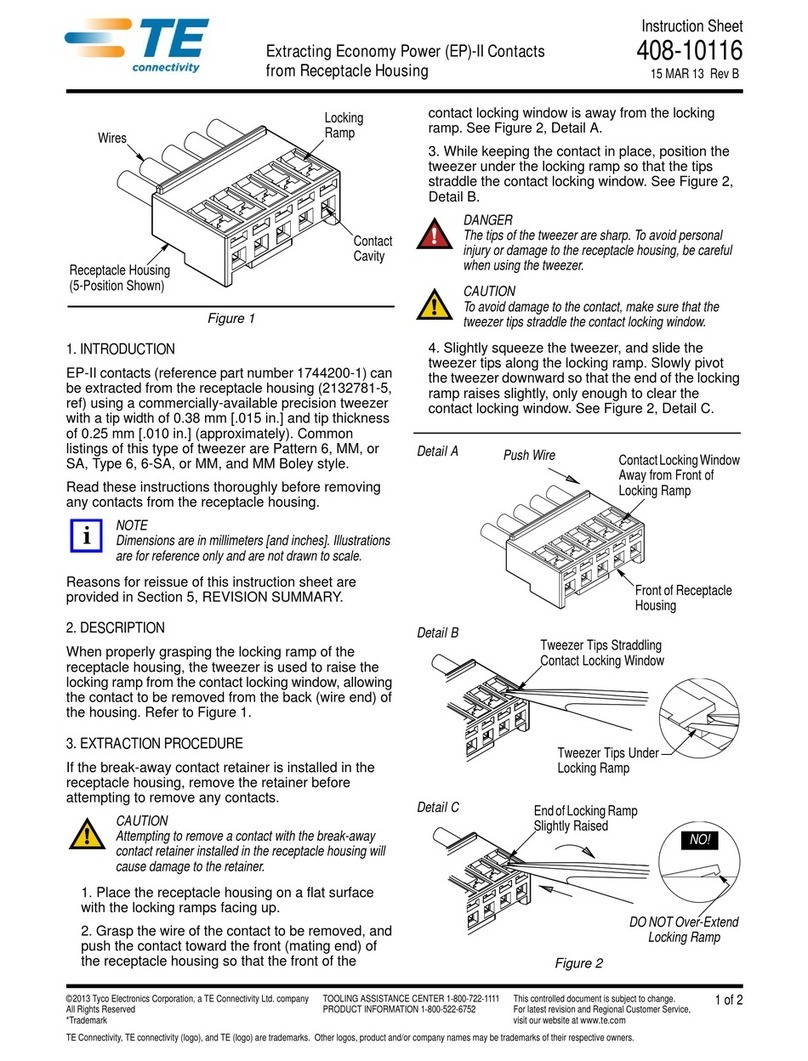
TE Connectivity HV-CP User manual

TE Connectivity

TE Connectivity HV-CP User manual

TE Connectivity RD-316 User manual

TE Connectivity

TE Connectivity RD-316 User manual

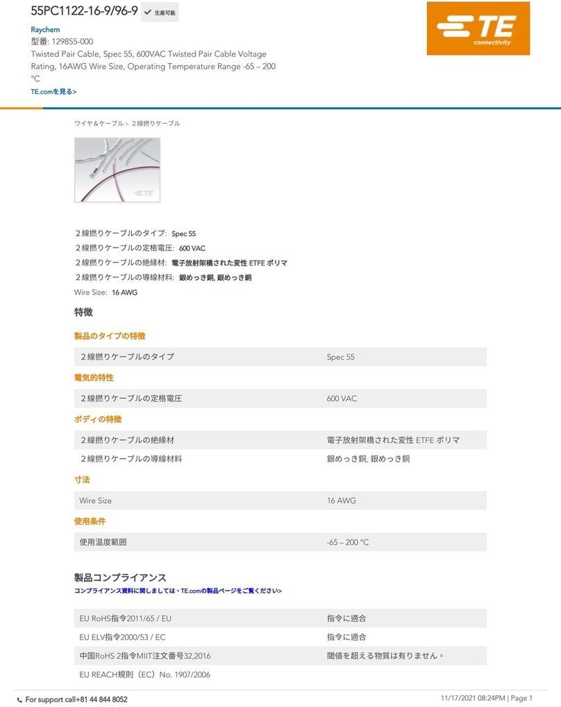
TE Connectivity 55PC1122-16-9/96-9 User manual

TE Connectivity

TE Connectivity 55PC1122-16-9/96-9 User manual

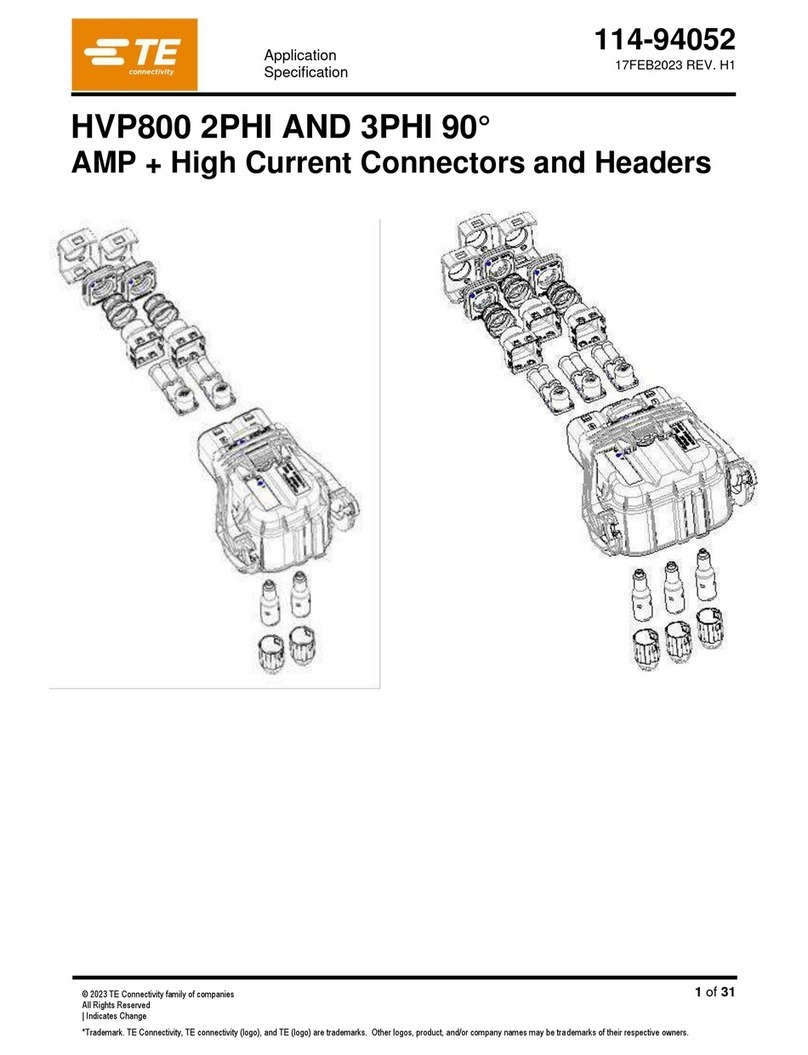
TE Connectivity HVP800 2PHI 90 User manual

TE Connectivity

TE Connectivity HVP800 2PHI 90 User manual

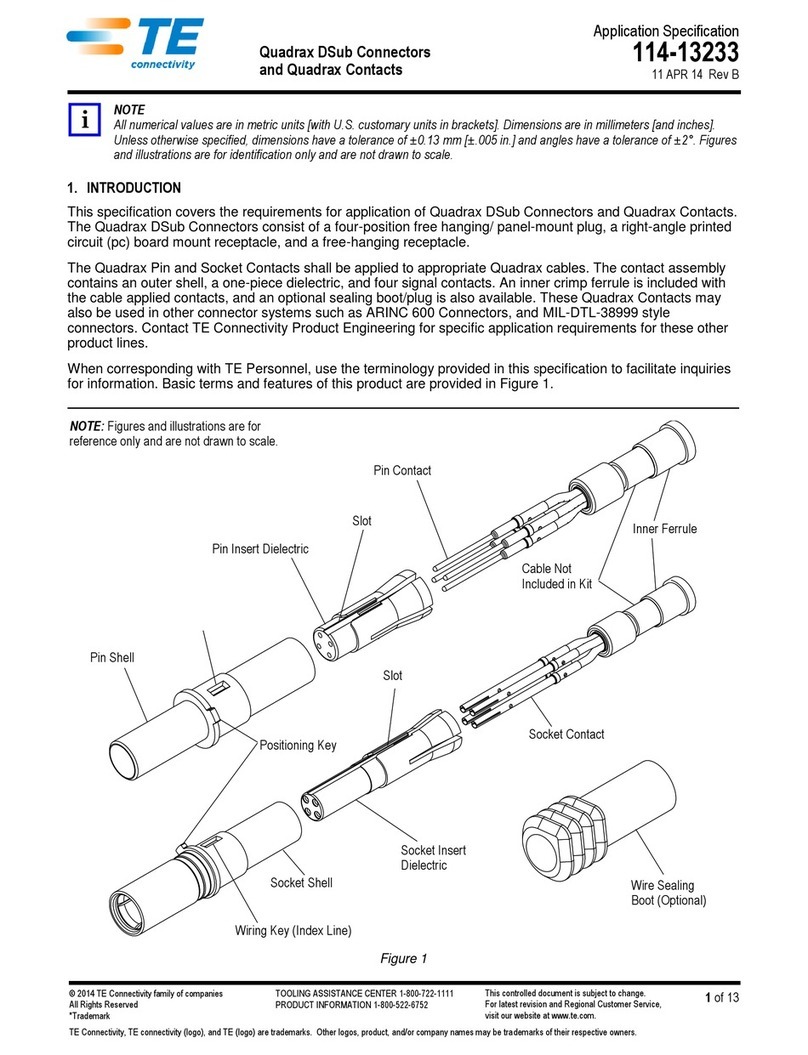
TE Connectivity Quadrax DSub User guide

TE Connectivity

TE Connectivity Quadrax DSub User guide

TE Connectivity CCS1 User manual

TE Connectivity

TE Connectivity CCS1 User manual

TE Connectivity DYNAMIC 5000 Series User manual

TE Connectivity

TE Connectivity DYNAMIC 5000 Series User manual

TE Connectivity DRC16 User manual

TE Connectivity

TE Connectivity DRC16 User manual

TE Connectivity Raychem LJSM Series User manual

TE Connectivity

TE Connectivity Raychem LJSM Series User manual

TE Connectivity 747564-9 User manual

TE Connectivity

TE Connectivity 747564-9 User manual

TE Connectivity VAL-U-LOK 3-1586040-6 User manual

TE Connectivity

TE Connectivity VAL-U-LOK 3-1586040-6 User manual

TE Connectivity TNC COAXICON Series User manual

TE Connectivity

TE Connectivity TNC COAXICON Series User manual

TE Connectivity AMP NETCONNECT 1499119-1 User manual

TE Connectivity

TE Connectivity AMP NETCONNECT 1499119-1 User manual

TE Connectivity AMPLIMITE HDP-20 User manual

TE Connectivity

TE Connectivity AMPLIMITE HDP-20 User manual

TE Connectivity HVA630-2phm User manual

TE Connectivity

TE Connectivity HVA630-2phm User manual

TE Connectivity D5000-S User manual

TE Connectivity

TE Connectivity D5000-S User manual

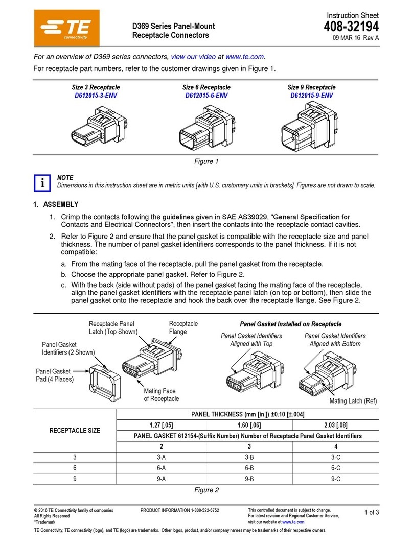
TE Connectivity D369 Series User manual

TE Connectivity

TE Connectivity D369 Series User manual

TE Connectivity QSFP-DD User guide

TE Connectivity

TE Connectivity QSFP-DD User guide

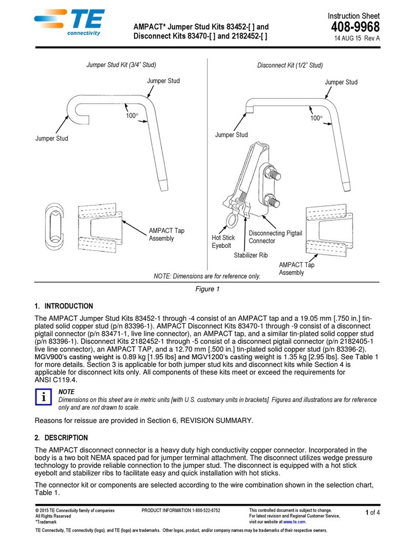
TE Connectivity AMPACT 83452 Series User manual

TE Connectivity

TE Connectivity AMPACT 83452 Series User manual

TE Connectivity RAYCHEM D-436 Series Reference guide

TE Connectivity

TE Connectivity RAYCHEM D-436 Series Reference guide

TE Connectivity SGI 1.25 User guide

TE Connectivity

TE Connectivity SGI 1.25 User guide

Popular Cables And Connectors manuals by other brands

Lenze EYP A A00Q01 Series Mounting instructions

Lenze

Lenze EYP A A00Q01 Series Mounting instructions

Multiplex Channel Plus 8200 instruction manual

Multiplex

Multiplex Channel Plus 8200 instruction manual

Milestone MP-DA2HD-4K user manual

Milestone

Milestone MP-DA2HD-4K user manual

Hollyland-Tech HLHD0108B user manual

Hollyland-Tech

Hollyland-Tech HLHD0108B user manual

OEZ CS-BD-B411 Instructions for use

OEZ

OEZ CS-BD-B411 Instructions for use

Staubli MC4-Evo 2 Installation and operation manual

Staubli

Staubli MC4-Evo 2 Installation and operation manual

Xplore xDIM quick start guide

Xplore

Xplore xDIM quick start guide

ELWORKS DRIBOX 200 SMALL instructions

ELWORKS

ELWORKS DRIBOX 200 SMALL instructions

Philips Line Cord SWL6146 Specifications

Philips

Philips Line Cord SWL6146 Specifications

Nexans Euromold K480TB/G installation instructions

Nexans

Nexans Euromold K480TB/G installation instructions

LED Group Robus VEGAS RVA67RGB-CONNP quick start guide

LED Group

LED Group Robus VEGAS RVA67RGB-CONNP quick start guide

Goobay 51768 user manual

Goobay

Goobay 51768 user manual

Siemens 3VL9400-4TC.0 operating instructions

Siemens

Siemens 3VL9400-4TC.0 operating instructions

Philips SWV3232W/10 user manual

Philips

Philips SWV3232W/10 user manual

Bose 839760-0010 Design Guide Supplement

Bose

Bose 839760-0010 Design Guide Supplement

Ohme Cable product manual

Ohme

Ohme Cable product manual

Aim EcuMaster EMU Black user guide

Aim

Aim EcuMaster EMU Black user guide

Clearfield FieldShield YOURx-Terminal installation manual

Clearfield

Clearfield FieldShield YOURx-Terminal installation manual

manuals.online logo
manuals.online logoBrands
  • About & Mission
  • Contact us
  • Privacy Policy
  • Terms and Conditions

Copyright 2025 Manuals.Online. All Rights Reserved.