manuals.online logo
Brands
  1. Home
  2. •
  3. Brands
  4. •
  5. Team Losi
  6. •
  7. Motorized Toy Car
  8. •
  9. Team Losi Double-XT User manual

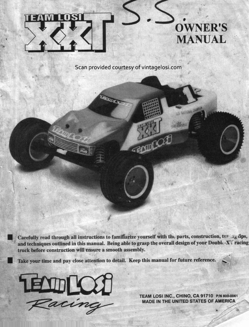
Team Losi Double-XT User manual

Other Team Losi Motorized Toy Car manuals

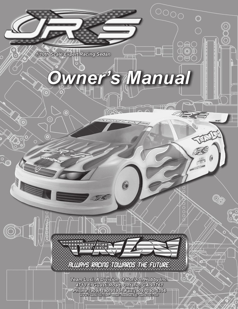
Team Losi JRX-2 User manual

Team Losi

Team Losi JRX-2 User manual

Team Losi l8ight Quick start guide

Team Losi

Team Losi l8ight Quick start guide

Team Losi XXX-SCT User manual

Team Losi

Team Losi XXX-SCT User manual

Team Losi Mini-Rock Crawler LOSB0222 User manual

Team Losi

Team Losi Mini-Rock Crawler LOSB0222 User manual

Team Losi XXX-T MF2 User manual

Team Losi

Team Losi XXX-T MF2 User manual

Team Losi Mini Sprint User manual

Team Losi

Team Losi Mini Sprint User manual

Team Losi STREET WEAPON User manual

Team Losi

Team Losi STREET WEAPON User manual

Team Losi TENACITY SCT User manual

Team Losi

Team Losi TENACITY SCT User manual

Team Losi 8IGHT User manual

Team Losi

Team Losi 8IGHT User manual

Team Losi LST XXL User manual

Team Losi

Team Losi LST XXL User manual

Team Losi Aftershock User manual

Team Losi

Team Losi Aftershock User manual

Team Losi XX4 User manual

Team Losi

Team Losi XX4 User manual

Team Losi 22 2.0 User manual

Team Losi

Team Losi 22 2.0 User manual

Team Losi Night Crawler LOSB0104 User manual

Team Losi

Team Losi Night Crawler LOSB0104 User manual

Team Losi mini-baja User manual

Team Losi

Team Losi mini-baja User manual

Team Losi LOS01008 User manual

Team Losi

Team Losi LOS01008 User manual

Team Losi 8ight RTR User manual

Team Losi

Team Losi 8ight RTR User manual

Team Losi Mini 8IGHT-T User manual

Team Losi

Team Losi Mini 8IGHT-T User manual

Team Losi LOSB0012LE User manual

Team Losi

Team Losi LOSB0012LE User manual

Team Losi Night Crawler User manual

Team Losi

Team Losi Night Crawler User manual

Team Losi XX4 User manual

Team Losi

Team Losi XX4 User manual

Team Losi EIGHT User manual

Team Losi

Team Losi EIGHT User manual

Team Losi 8IGHT-E User manual

Team Losi

Team Losi 8IGHT-E User manual

Team Losi Micro Rock Crawler User manual

Team Losi

Team Losi Micro Rock Crawler User manual

Popular Motorized Toy Car manuals by other brands

Reely Dune Fighter 3S operating instructions

Reely

Reely Dune Fighter 3S operating instructions

REVELL 1970 Chevelle SS 454 manual

REVELL

REVELL 1970 Chevelle SS 454 manual

Jamara Mercedes-AMG GLE 63 Instruction

Jamara

Jamara Mercedes-AMG GLE 63 Instruction

Eduard Humber Scout Car Mk.I exterior quick start guide

Eduard

Eduard Humber Scout Car Mk.I exterior quick start guide

Jamara VW T1 Bus Instruction

Jamara

Jamara VW T1 Bus Instruction

REVELL 68 CHEVY CHEVELLE SS 396 manual

REVELL

REVELL 68 CHEVY CHEVELLE SS 396 manual

Schumacher Pro Cat instruction manual

Schumacher

Schumacher Pro Cat instruction manual

Tamiya TT-01 TYPE E instruction manual

Tamiya

Tamiya TT-01 TYPE E instruction manual

Eduard Krupp Protze 6x4 1/48 quick start guide

Eduard

Eduard Krupp Protze 6x4 1/48 quick start guide

New Bright 61072UEP quick start guide

New Bright

New Bright 61072UEP quick start guide

Team Durango DEX410v5 manual

Team Durango

Team Durango DEX410v5 manual

Jamara Mercedes Actros Muldenkipper 2,4 GHz Instruction

Jamara

Jamara Mercedes Actros Muldenkipper 2,4 GHz Instruction

PLAYMOBIL 9536 manual

PLAYMOBIL

PLAYMOBIL 9536 manual

Atomic BZ3 instruction manual

Atomic

Atomic BZ3 instruction manual

Jamara McLaren Senna 2,4GHz instructions

Jamara

Jamara McLaren Senna 2,4GHz instructions

Aiyaplay 370-290V00 user manual

Aiyaplay

Aiyaplay 370-290V00 user manual

ZEROTRIBE Zetricks ZT1144 instruction manual

ZEROTRIBE

ZEROTRIBE Zetricks ZT1144 instruction manual

INJUSA 412 Assembly instructions

INJUSA

INJUSA 412 Assembly instructions

manuals.online logo
manuals.online logoBrands
  • About & Mission
  • Contact us
  • Privacy Policy
  • Terms and Conditions

Copyright 2025 Manuals.Online. All Rights Reserved.

•
OWNER'S
MANUAL
Scan
provided courtesy
of
vintagelosi.com
• Carefully read through all instructions to familiatize.yourself with th(, parts, construction, tur .
.1
.5
lips,
and techniques outlined inthismanual. Being able to grasp theoverall design
of
your
Doubh
..
·XT racuig
truck before construction will ensurea smooth assembly.
• Take your time
and
pay close attention to detail. Keep this manual for future reference. ..
TEAM LOSIINC., CHINO, CA 91710
PIN
800-0061
MADE IN THE UNITED STATES OF AMERICA
,.......,
~
WELCOME DOUBLE-X OWNER!
Thank you for purchasing the Team Losi Double-XT. This kit represents the latest in 1/10 scale truck raci
ng
tec
hn
olog
y.
Based on the Double-X off-road
buggy
which revolutionized the 1/10 scale market, the Double-XT is the result
of
intense
design
and
development efforts by the Team Losi racing team
and
design
staff. In its very first
out
ing
at
the 1994 NORR
CA
National Championships, it
took
first place honors. This kit utilizes extraordinary
design
and
construction that has made
Tea
m
Los1
famous world wide. The
use
of
specialized materials,
computer
aided
design
(CAD),
computer
aid
ed
manufacturing
(CAM) and
fi
nite element analysis (FEA stress analysis) is unequaled in the R/C racing world.
Before starting construction
of
your
Double-XT, please take a
moment
to read
through
these instructions. This will
minimize building time and
get
you
on
the track
sooner
.
Add
itionally,
we
have included a tip section in the
bac
k
of
the manual
to help you tune
your
Double-XT
for
optimum
performance.
Once again, thank
you
for
choosing
the
Doub
le-XT.
Tea
m Losi is racing to help
you
win.
TEAM LOSI
1. INTRODUCTION
DOUBLE-XT COMPLETED KIT DIMENSIONS
Length:
15
.
5"
Wheel base:
11"
Front Width: 12.5"
All dimensions
at
ride hei
gh
t.
NOTES & SYMBOLS USED
*Note: this
is
a
common
note.
It
is used to callattention
to specmc details
of
a certain
step
in the assembly.
@ IMPORTANT NOTE: Even
if
you
are familiar with
Team Losi kits, besure and
pay
attention tothese notes. They
poi
nt
out
very
important
details
about
a certain
step
in the
assembly. Do
not
ignore these notes!
R:J
This flag designates a performance tip. These tips
are
not
necessary,
but
can
improve the performance
of
your
Double-XT truck.
KIT/MANUAL ORGANIZATION
TheTeam Losi Double-XT is
composed
of
different
bags
marked A through H. Each
bag
conta
ins all
of
the parts nec-
essarytocomplete a particular
section
of
the Oouble-XTtruck.
Some
of
these bags have su
bassembly
bags within them. It
is essential
that
you open
only
one
bag
at
a time
and
follow
the correct
sequence
, otherwise
you
may
face difficulties in
finding the right part. It is helpful
to
reac;1
throu
gh
the instruc-
tions
for
an entire
bag
pr
i
or
to
starting assembly. Key
num
-
bers (in parenthesis) have
been
assigned to
each
part and
remain the
same
throughout
the manual. For
your
conve-
nience,an actual size hardware identification
guide
is included
with each step.
To
check
a part, hold
it
against the
si
lhouette
Rear Width: 12.6" Height: 5.
5"
Weig
ht
will vary
depending
on
accessories.
until the correct part is identified. In
some
cases extra hard-
wa
re
has
been
supplied
to replace easily lost parts. Different
fits have beendesigned into plastic parts (i.e.press, net,loose).
To
insure that parts are
not
lost during construction,
it
is rec-
ommended
that you
work
over
a towel
or
mat
to prevent parts
from rolli
ng
away.
IMPORTANT SAFETY NOTES
1. Select an area
for
assembly that is away from the
reach
of
small children.
The
parts in the kitare small andcan
be swallowed
by
children, causing choking
and
possible in-
ternal injury.
2.
The
shock
fluid
and
greases supplied should be kept
out
of
children's reach. They were
not
intended for human
consumption!
3. Exercise care when using any
hand
tools, sharp in-
struments, and
power
tools
during
construction.
4. Carefully read
all
manufacturer's warnings and cau-
tions tor
any
glues
or
paints
that
may
be
used
for
assembly
purposes.
TOOLS REQUIRED
Team Losi has
supplied
all allen wrenches
and
a special
wrench
that
is needed
for
assembly
and
adjustments. T
he
following
common
tools will also
be
required: Smallflatblade
screwdriver, needle nose pliers, regular pliers,scissors
or
other
body
cutting/trimming tool. 3/
16
",
1/4
",
and
3/8"
nut
drivers
are optional.
/
RADIO/ELECTRICAL
A suggested radio layout
is
provided
in
this manual. Your high performance R/C center should be consulted
specifics
on
radio/electrical equipment.
HARDWARE IDENTIFICATION
When
in
question, use the hardware identification guide in each step. For screws, the prefix
number
designates the
screw size and
number
of
threads per inch (i.e. 4-40
is
#4
screw with 40 threads per inch
of
length). The fraction following
designates the length
of
the threads for caphead screws,
and
the overall length for flathead screws. Bearings
and
bushings
are referenced
by
the
inside diameter x outside diameter. Shafts
and
pins are diameter x length. Washers are described by
inside diameter
or
the
screw
size that will pass through the inside diameter. 'E' clips are sized by the shaft diameter that they
are attached to.
MOTORS AND GEARING
Your Double-XT truck includes
an
88 tooth, 48 pitch
spur
gear. The overall internal gearbox ratio is 2.61 :1. The external
pinion
gear
will determine
your
gear
ratio.
To
figure
out
thefinal drive ratio first dividethe
spur
gear
size bythe pinion gearsize.
Say you are using a
20
tooth pinion gear, you would divide
88
(spur
gear
size)
by
20 (pinion
gear
size). For example:
(88 +
20
=4.4)
So
4.4
is
your
external drive ratio. Now multiply the internal drive ratio (2.61) by the external drive ratio (4.4).
Forexample: (2.61 x
4.4
=
11.484)
This tells you that by using a
20
tooth pinion
and
a 88 tooth
spur
gear
, the final drive ratio
is 11.484:1.
Consult
your
high performance
shop
for recommendations to suit
your
racing style
and
class. Thechart below lists some
of
the more common motor types
and
a recommended initial gearing for that motor. Ratios can be adjusted depending
on
various track layouts, tire sizes,
and
battery types. q:j1
"i
1.
~
:
REC
OM
MENDED INITIAL
GEA
RING FOR
CO
M
MO
N MOTORS f '
~
\
PINION
Sf
•·
f'
ifO
SPUR
22
1/J
. " ( 88
{0
I
Lftf
21
II
. tfl 88
(0
.Ct1l
16
r-1
.
tt&
88
Jtf,)))
12 turn modified 17
r~
.
s t 88
J1
.
51
0
13 turn modified 18 }1
cS
88
(1..1'5"'1
14
turn modified 19 I
z.
.1/.p 88
1
z..o
S
~
15 turn modified
20
,,,
74
88 ; 1,4kc/
16 turn modified
21
It
.
IY
88
,o
.
Cfn
17
turn modified
22
/O .
Y,(
88 I
o,
4
lf
18 turn modified
i~
I
IJ
,
7..1
~~
q ,
&)?;{.,
'1
:
71
TABLE OF CONTENTS
~
.
5<t
't
1.
INTRODUCTION ...............
..
....................
..
...... i 3. BAG B ............................................
..
...
.................
..
5-10
Completed Kit Dimensions
..
....
..
..
..
............
...
i 4. BAG C ..................................................................
11
-15
Notes & Symbols ........................................... i 5. BAG D ................................................................. 16-
21
Kit Manual Organization
..
...................
....
....
..
6. BAG E
...
..
.
..
.........
...
..
...
..
...
..
...
..
....
..
..
...
..
.
...
.....
..
.
...
22-26
Important Safety Notes ...............................
..
7. BAG F ........
...
..
.......................
..
......
..
....
..
.
..
..........
27
-30
Tools Required .............................................. 8. BAG G
..
..
.........
..
..
........................
..
...........................
31
Radio/Electrical ...
..
..
..
..
...
..
..
.
..
......
.....
..
......
..
..
ii
9. BAG H ...................................................
..
............ 32-34
Hardware Identification .
..
...
....
..
.................
..
.
ii
10. Glossary........................
..
....................................... 35
Motors & Gearing .
....
..
............
..
..
..
..
..
....
.
..
..
..
.
ii
11. Team Tips
....
..
..
..
..
.
..
.
...
.................
..
................... 36-37
2.
BAGA
..
...............
....
..
..
................................ 1-4 12. Spare parts .......................................................
38
-40
Team L
osi
Is
continually
changing
and
Improving
designs; therefore, the
actual
part
may
appear
slightly
different
than the Illustrated part. Illustrations
of
parts
and
assemblies
may
be
slightly
distorted
to
enhance
pertinent
details.
ii

BAGA
Fig 1.
Step 1. Attach
the
front
bulkhead
(1
) to the main
chassis (2) by
aligning
the
bottom
hinge holes
on
the
bulkhead (1)
and
the
main chassis
(2
). Once the holes
ar
e aligned, carefully
tap
the 1/8"
lower
bu
l
khead
hinge
pin (3)
through
both
pieces until the hinge pin
(3)
is cen-
tered. * U
se
the 1/8" hinge
pin
with the
la
r
ge
groove in
th
e cente
r.
• NOTE:
The
l
ower
hingepin fit is
VERY
TIGHT! Be
sure
th
atthe holes are aligned
and
tap pin
in
to p
la
ce.
St
ep
2. Secure the pin
by
threading a 2-56 x5/16"
button head
screw
(4
) into the small hole in the
top
, rear
of
the front
bulkhead
(1
).
Thread
the
screw
(4) all the
way in.
Step 3. Attach
the
front chassis stiffener (5)
to
the
fr
ont
bulkhead
(1)
by
aligning the holes in the stiffener
(5) with the holes in the
top
hinge
of
the
bulkhead (1).
Secure
by
inserting
the
1/8"
upper
bulkhead hinge pin
(6) through
both
the
bulkhead
(1)
and
stiffener (5) * Use
th
eshortest 1/8" h
in
ge
pin
wi
thout a groove in the cente
r.
* NOT
E:
The hi
nge
pin
fit is ti
ght
! Lightly tap the
hi
ng
e pin through
bot
h parts untilit is centered.
Step
4.
Center
the
hinge
pin
(6
)
and
attach an 1/8"
'
E'
clip (7)
to
each
end
of
the
hinge
pin
(6).
Fb
When
removing
the
front bulkhead
for
any
rea-
son, the 2-56 x 5/16"
button
head
screw
must
be
com
-
pletely
remo
v
ed
before removing t
he lower
hinge pin.
® @
Fig 2.
St
ep
5.
Insert
a
3/8
" ball
stud
(8) into
ea
ch
ofthe
inside
ho
les on the
bottom
of
the
shock
tower
(9).
Mount
the ball
studs (8) from the rear
as
shown
.
St
ep
6. Insert a 4-40 x 7/8"
cap
head
screw
(10) from
th
e rear,
thr
ou
gh
the
third
hole in
on
the
top
of
the
shock
tow
er (9)
on
each
side
. Thread a
top
shock
mount
bushing
11) onto
each
of
the
two
screws
(1
0)
and
tighten.
e
IMPORTANT
NOTE:
Remove all flashing from the
bottom of t
he
front
shock
tower. This will insure
proper
fit
of
the front sh
ock
t
ower
to
the
front bulkhead.
,__
__
__,0-L_
_ _
___J
0
1
~
U,__
O _
__
__.®
@1)
Figu
re
1
9
Figure 2
BAG A
(Continued)
@
Fig
3.
St
ep 7. Attach thefrontsho
ck
tower (9) to the front side
ofthe
frontbulkhead (1) with four 4-40 x 3/8"cap head screws
(
12
).
Step 8. Attach the front body mount {
13
) to the front
side
of
the front
shock
tower
{9)
withtwo 4-40 x 3/
8"
cap head
screws (12) as shown.
~10
----------~o
~
@
Fig
4.
t
ep
7. lnse a ont axle (14) into each of th' front
pindl (left (15 , right 6)] as shown. The hole in
th~
should line u · the hole in the spindle
{15)
, {16).
Qe
p B
AUaeh
t!
1a rlgtitspindle {
16
) toone
of
the spindle
carriers {17) by aligning the holes
in
each and inserting a
3/32"x 1.050" hinge pin {18) through the spindle carri
er
{17),
spindle (16),
and
axle (14). Center the hinge pin {18) and
secure itwith two 3/32" 'E' clips
{19
).
e IMPORTANT NOTE: There are two sizes of 'E'
clips
in
th
is
assembly bag. Be sure to usethe small 'E' cli
ps
on the 3/32" pins.
Step 9. With the hinge pin
(18
) still centered, thread a
5-40 set screw (20) into the back side
of
the axle {14) and
tighen.
Step 10. Repeatfor the left spindle {15)and thesecond
spi
ndle carrier (17).
Figure 3
Fi
gure
4
2
18
17
BAG
A (Continued)
® @
Fig
5.
Step
11
. Insert a 3/8" ball
stud
(8) into the
top
of
each
sp
1ndle earner (17)
and
tighten. Insert a 4-40 mini lock
nut
(
21
) mto the hex area in
each
spindle (15),
(1
6), thread a
3
1 1
~
baUstud (22) in from
the top
and
tighten.
e
IMPORTANT
NOTE:
Do
not
over tighten the ball
sruds!
ID
Fig
6.
'
'
~
~
'
'
Figure 5
~
mc..__
_ _ _ m
Step 12. Attach
the
right spindle
and
carrier assembly
to
the right front suspension
arm
(24) as
shown
. Line
up
the
holes in the
spindle
carrier (17) with
the
holes in thefront arm (24), insert a 3/32"x 1.050" hinge pin (18)
and
attach a 3/32" 'E'
clip (19)
to
both
sides
of
the
hinge pin (18).
8
IMPORTANT
NOTE: There are
two
sizes
of
'E' clips in this assembly bag. Be sure
to
use
the
small 'E' clips on the
3/
32
" pins.
Step
13
. Attach
the
arm
(24)
to
the rightside
of
thefront bulkhead
(1)
by
inserting
the
1/8" innerfront hinge pin (25), from
the front, through the
arm
(24)
and
bulkhead (1).
Step 14. Insert a 1/8" 'E' clip (7) in the rear groove
of
each hinge pin (25).
Step 15. Slide
the
front hinge pin brace (26) over the front
of
both hinge pins (25). Be sure that the brace (26) is
installedcorrectly
so
that
the
'E'
clip
grooves in both hinge pins (25) are exposed. Secure
th~
brace
by
attaching a 1/8"'E' clip
(7)
to
the front
of
each hinge pin (
25
).
Step 16. Repeat steps 12 through 15 for leftside with the left suspension arm (23).
F
igure
6 /
3
BAG
A (Continued)
UU!J:'IIIIID
0
!l!ll
llil!lji
l!lllfl
Figure
7
Figure
7A
Fi
g 7.
Step 17. Thread a plastic rod end (27) onto each end
of
a 2-1/2" turnbuckle (28
).
Tighten both rod ends (27) equallyuntil
the rod
is
the same length
as
the rod in Fig. 7A. Make two camber link assemblies.
F
ig
8.
Step 18. Place a "foam thing" (29) over each
of
the ballstuds on the spindle carriers (17) and the
shock
tower (9
).
Next,
attach one side
of
the
camber
link assembly to the ba
ll
stud on the shock tower (9) and the otherside
to
the ball stud on the
spindle carrier (
17
). Attach a camber link to both the left and right side.
RJ
Try
to
mountall
of
the camber links so that the threads adjustthe same direction. This makes it much easier to make
adjustments later.
29
Figure 8
4
BAG B
Fig 9. @
Step 1. Place servo saver bottom (30) overservo saver
post (
31
)
and
slide servo saver bottom all
of
the
way down.
Be sure that the
hex
in the servo saver post (31) is inserted
1nto the hex in the servo saver bottom (30).
Step
2.
Slide
the
servo saver
top
(32) down over the
servo saver
post
(31)
so
that it rests against the servo saver
bottom (30). The
arm
on
the servo saver
top
(32) and the
arm
on
the
servo saver bottom (30} should point in opposite
directions.
Step 3. Slide the servo saverspring (33) over theservo
saver post (31)
and
push
it into
the
recessed area. Install the
servosaverspring
cap
(
34)
and
thread the 6-40 lock
nut
(35)
onto the threads
of
the
servo saver post (31).
Step 4. Tighten
the
6-40
lock
nut
(35) all
of
the way
down
and
then
loosen it
two
full turns (i.e.360° x 2). This is a
good
starting point
for
the adjustment. Once assembly is
complete,
if
you
wish
,
the
servosavercan beadjustedti
ghter
or
looser.
Fig 1
0.
@ @
Step 5. Insert a 4-40 mini
lock
nut
(21) into each
of
the
two hexareas in theservosaver bottom (30). Thread a 3/16"
ball
stud
(22) into each
nut
(21)
and
tighten. Insert a 4-40
mini lock
nut
(21) into
the
hex area in the servo saver top.
Thread a
3/16
" ball
stud
{22) into the
nut
(21)
and
tighten.
Step 7. Insert a 4-40 mini
lock
nut
(21
) into each
of
the
two
hex areas in the steering idler
arm
(36). Thread a 3/16"
ball stud (22) into each
nut
(21)
and
tighten.
.•,. 0
p:
n:
IU
IG
Fig 1
1.
Step 8. Thread a plastic rod
end
(27) onto each
end
of
a 2 1/4" turnbuckle (37). Tighten both rod ends (27) equally
until the
completed
tie rod is the
same
length as the one
in
fi
gure 11A.
Make
two
tie rod assemblies.
Step 9. Thread a short plastic rod
end
(38) onto each
end
ofthe
1-1/8"
tu
rnbuckle (39). Tighten both rod ends (38)
equally until the
completed
drag link is the same length as
the
one
in figure
11A
.
Figure 9
Figure
10
Figure
11
Fi
gur
e JJA
~
-
T
·-~
@ 39
o~=
lllllc
==tQ~
I
==-•
.._E===:30
5
BAG
B (t;ontlnueaJ
Flg. 12
Step
10
.
Snap
one
end
of
the
short
drag
link
to
the ri
ght
ball
stud
(
22)
on
the
servo
s
aver
bottom
(3
0). Snap t
he
o
ther
end
to
the left ball st
ud
on
the steering i
dler
arm (
36
).
*NOTE: Be sure to snap the rod onto the correct ball
studs
as
shown!
10
01
@ ®
Fig
13
.
Step
11
.
Insert
a 3/
32
" x 3/16"
bu
shing (40) into the
two
large holes in the
bottom
of
the steering brace
(41
),
cham
-
fered end first. Insert the
other
two
bushings
(40) into the
two
holes in
the
main chassis (2).
*Note: Trim all flashing from
th
e bushings to ensu
re
proper fi
t.
Step
12. In
sert
a 3/32" x .930"
hinge
pin (42) through
the hole in
the
steering idler
arm
(36)
and
position it as
shown
in fig. 13A. Place
the
servo
save
r
assembly
and
the steeri
ng
idl
er
arm (36)
into
the b
ushings
(
40
) in the chassis (
2)
so
th
at
the installed
drag
link
is in the front.
Step
13. Place
the
steering brace
(41
)
on
t
op
of
the
servo
sa
ver
assemb
ly
and
steering idler
arm
(36)
be
i
ng
sure
that the
bush
i
ngs
(40)
slide
ov
er
the pins.
Step 14. Attach the
steer
i
ng
brace to the chassis (2)
using
two
4-40 x 3/8"
cap
head
screws (12).
e
IMPORT
A
NT
NOTE: Tighten the
two
4-40 screws
all the
way
and
then
back
them
off
1/8
of
a turn. This will
keeptheposts
on
thechassis from "taking a
set
" if
they
should
twist at all.
RJ
If
y
ou
should
ev
er
need
to
remove the small bush-
ings, the easiest
way
to
get
them
out
is to slightlythread a 4-
40
screw
in
to
them
and
pull
th
em
out.
Figure
12
3&
Figure 13
Figure 13A
6
41
BAG B (Continued)
Fig 14.
Step 15. Snap one end
of
a completed tie rod to the idler arm (36). Snap the other end to the right side spindle (16).
Attach the othertie r
od
assembly to the servo saverassembly and the
le
ft spindle (15).
R:;
Once again, assure that all turnbuckles are mounted with the threads in the same direction for easier adjustment
later!
Fig 15.
*Note:
If
you
do
not
have yourservo
at
this time,
sk
ip to
Bag C
and
continue assembly. It is recommended that the
servo
be
installed
at
this time since much
of
the front
end
is
bu
il
taroundthe servo
and
minor
disassemblywill
be
requ
ir
ed
to insta
ll
it later.
e IMPORTANTNOTE:
If
the servo mounting instruc-
tions are notfollowed carefully,yourservo maybe damaged!
Step 16. Using a file
or
a Dremel tool, trim the two lower
ears off
of
your servo (not included) as shown in figure 15.
Be
very careful totrim the
co
rre
ct
ears! Ifthe wrong ears are
trimmed, your servo will
not
be able to be mounted unless
the servo case is replaced.
e IMPORTANT NOTE: It is not recommended that
you use cutters or a hobby knife to remove the servo ears.
Some cases are made
of
very brittle material and damage to
yourservo case may result.
Figure 14
Figure 15
7