TEC Thermocool User manual

USER MANUAL

.
1
Contents
INSTRUCTIONS FOR THE INSTALLER: these are intended for the qualified technician who must
carry out an adequate inspection of the gas system, install the appliance, set it functioning and test it.
INSTRUCTIONS FOR THE USER: these contain user advice, the description of the controls and the
correct procedures for cleaning and maintenance of the appliance
Page
Number
1 INSTRUCTIONS FOR SAFETY AND USE _________________
4
____________________ 2
2 RECYCLING INSTRUCTIONS - OUR ENVIRONMENT POLICY ___________________
_
3 INSTALLING THE APPLIANCE_____________________________________________
_5
4 ADAPTATION TO DIFFERENT TYPES OF GAS _______________________________
12
5 FINAL OPERATIONS ____________________________________________________
6 DESCRIPTION OF THE CONTROLS ON THE FRONT PANEL____________________
15
17
19
21
2
7 USING THE HOB________________________________________________________
8 USING THE OVEN ______________________________________________________
9 ELECTRONIC PROGRAMMER (ON CERTAIN MODELS ONLY) __________________
2
10 DIGITAL TIMER (ON CERT AIN MODELS ONLY) _____________________________
_
24
11 ANALOGUE CLOCK (ON CERTAIN MODELS ONLY) __________________________
_
25
12 CLEANING AND MAINTENANCE __________________________________________
25
13 EXTRAORDINARY MAINTENANCE _________________________________________ 27
14 AVAILABLE ACCESSORIES_______________________________________________ 28
15 COOKING WITH THE OVEN_______________________________________________29

1 INSTRUCTIONS FOR SAFETY AND USE
THIS MANUAL IS AN INTEGRAL PART OF TH E APPLIANCE. THEREFORE IT MUST BE KEPT IN
ITS ENTIRETY AND IN AN ACCESS IBLE PLACE FOR THE WHOLE WORKING LIFE OF THE
COOKER. WE ADVISE YOU TO READ THIS MANUAL AND ALL THE INFORMATION IT
CONTAINS CAREFULLY BEFORE USING TH E COOKER. ALSO KEEP THE SERIES OF
NOZZLES PROVIDED. INSTALLATION MUST BE CARRIED OUT BY QUALIFIED PERSONNEL IN
ACCORDANCE WITH THE REGULATIONS IN FORCE. THISA PPLIANCE IS INTENDED FOR
DOMESTIC USE AND CONFORMS TO THE EEC DIRECTIVES CURRENTLY IN FORCE. THE
APPLIANCE HAS BEEN BUILT TO CARR Y OUT THE FOLLOWING FUNCTION: COOKING AND
HEATING UP FOOD; ALL OTHER USES SHOULD BE CONSIDERED UNSUITABLE.
THE MANUFACTURER CANNOT BE HELD LIABLE FOR USES OTHER THAN THOSE INDICATED.
NEVER LEAVE DISCARDED PACKAGING UNATTENDED IN THE HOME.
SE PARATE WASTE PACKAGING MA TERIALS BY TYPE AND CONSIGN THEM TO THE
NEAREST SELECTIVE WASTE COLLECTION CENTRE.
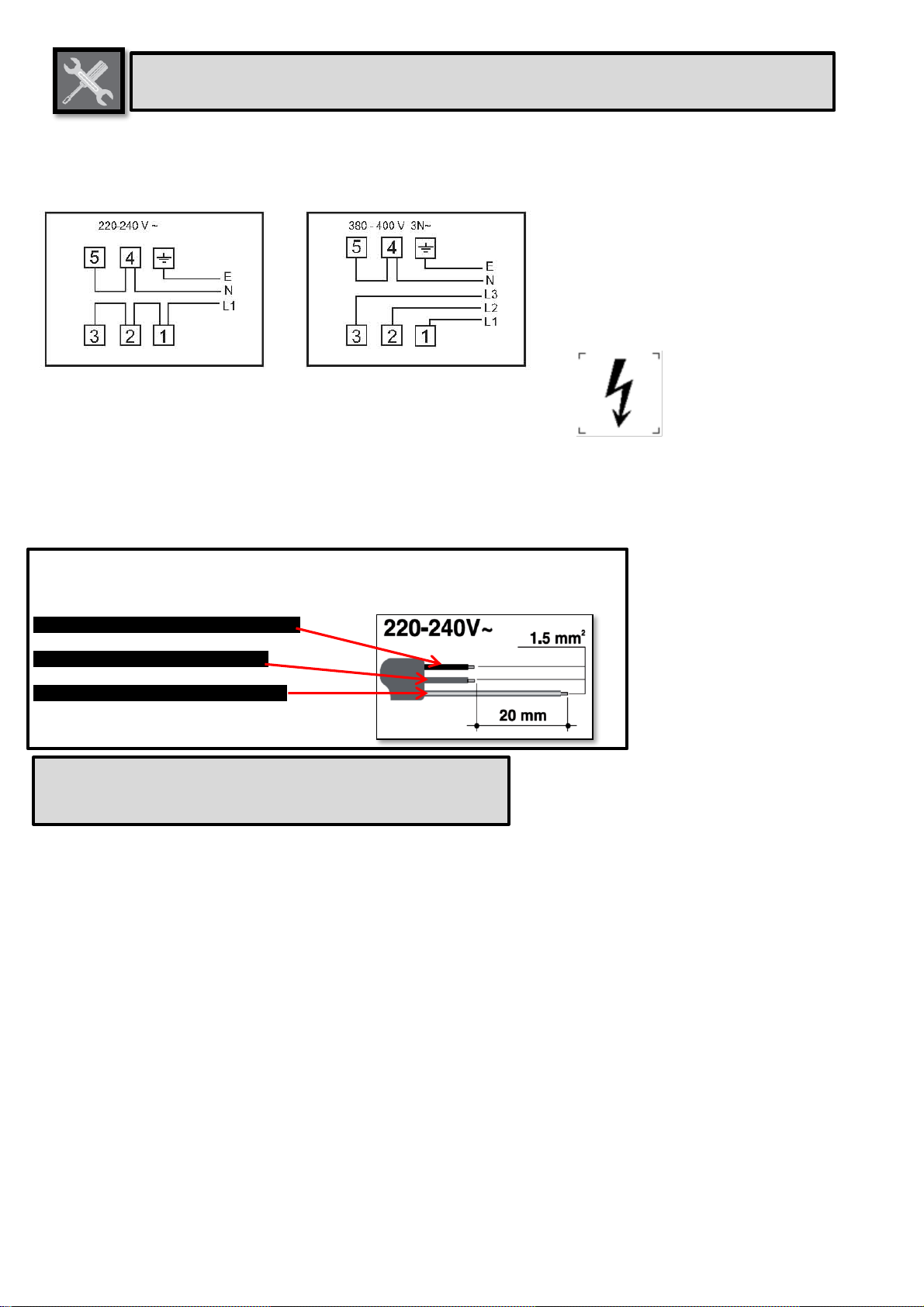
IT IS OBLIGATORY FOR ALL ELECTRICAL EQUIPMENT TO BE EARTHED ACCORDING TO
THE METHODS LAID DOWN BY SAFETY REGULATIONS.
THE PLUG TO BE CONNECTED TO THE POWER SUPPLY CABLE AND ITS SOCKET MUST BE
OF THE SAME TYPE AND CONFORM TO THE REGULATIONS IN FORCE.
THE SOCKET MUST BE ACCESSIBLE AFTE R THE APPLIANCE HAS BEEN BUILT IN.
NEVER UNPLUG BY PULLING ON THE CABLE
IMMEDIATELY AFTER INSTALLATION, CARR Y OUT A QUICK TEST ON THE APPLIANCE
FOLLOWING THE INSTRUCTIONS PROVIDED LATER IN THIS MANUAL. SHOULD THE
APPLIANCE NOT FUNCTION, DISCONNECT IT FROM THE POWER SUPPLY AND CALL THE
NEAREST TECHNICAL ASSISTANCE CENTRE.
NEVER ATTEMPT TO REPA IR THE APPLIANCE.
ALWAYS CHECK THAT THE CONTROL KNOBS ARE IN THE (OFF) POSITION WHEN YOU
FINIS H U SING THE APPLIANCE.
NEVER PLACE FLAMMABLE OBJCETS IN THE OVEN: IF IT SHOULD ACCIDENTALLY BE
SWITCHED ON, THIS MIGHT CAUSE A FIRE.
THE IDENTIFICATION PLATE WITH THE TECHNICAL DATA, SERIAL NUMBER AND BRAND
NAME IS IN A VISIBLE POSITION ON THE BACKSIDE OF THE OVEN.
DO NOT REMOVE THIS PLATE FOR ANY REASON.
NEVER PLACE PANS WITH BOTTOMS WHICH ARE NOT PERFECTLY FLAT AND SMOOTH ON
THE HOB RACKS.
NEVER USE PANS OR GRIDDLES WHICH PROJECT BEYOND THE OUTSIDE EDGE OF THE
HOB.
HOLD THE GLASS LID WITH YOUR HAND WHILE LOWERING IT.
WARNING: THE GLASS LID CAN SPLINTER IF OVERHEATED.
TURN OFF ALL THE BURNERS AND WAIT FOR THEM TO COOL DOWN BEFORE CLOSING IT.
DURING USE THE APPLIANCE BECOMES VERY HOT .TAK E CARE NEVER TO TOUCH THE
HEAT ING EL EMENTS INSIDE THE OVEN.
2
Presentation

THE USE OF THIS APPLIANCE IS NOT PERMITTED TO PEOPLE (INCLUDING CHILDREN) OF
REDUCED PHYSICAL AND MENTAL ABILITY, OR LACKING IN EXPERIENCE IN THE USE OF
ELECTRICAL APPLIANCES, UNLESS THEY ARE SUPERVISED OR INSTRUCTED BY ADULTS
OR PEOPLE RESPONSIBLE FOR THEIR SAFETY.
INSTALL THE APPLIANCE SO THAT WHEN OPENING DRAWERS AND DOORS OF UNITS
POSITIONED AT THE LEVEL OF THE HOB THER E IS NO POSSIBILITY OF MAKING CONTACT
WITH PANS POSITIONED ON TOP OF IT.
THIS APPLIANCE IS MARKED ACCORDING TO EUROPEAN DIRECTIVE 2002/96/EC ON
WASTE ELECTRICAL AND ELEC TRONIC EQUIPMENT (WEEE).
THIS DIRECTIVE DETERMINES THE STANDARDS FOR THE COLLECTION AND RECYCLING
OF WASTE ELECTRICAL AND ELECTRONIC EQUIPMENT APPLICABLE THROUGHOUT THE
EUROPEAN UNION.
BEFORE THE APPLIANCE IS PUT INTO OPERATION, ALL LABELS AND PROTE CTIVE FILMS
APPLIED INSIDE OR OUTSIDE MUST BE REMOVED.
3
Presentation
The manufacturer cannot be held liable for damage to persons or things caused
by failure to comply with the above requirements or by tampering with any part of the
appliance or by the use of non-original spare parts.

2 RECYCLING INSTRUCTIONS - OUR ENVIRONMENT POLICY
Our household appliances are only packaged using non-pollutant, environment-friendly, recyclable
materials. Please help by disposing of the packaging correctly. You can obtain the addresses of
collection, recycling and disposal centres from your retailer or from the competent local organisations.
Never leave all or part of the packaging lying around.Your old appliance also needs to be disposed of
correctly.Important: deliver the appliance to the local agency authorised for the collection of household
appliances no longer in use.Correct disposal enables intelligent recovery of valuable materials.
Refrigeration appliances contain gases which may damage the environment; it is therefore important to
ensure that the refrigeration circuit pipelines are not damaged until the competent service has accepted
delivery of the appliance.Before disposing of your appliance it is important to remove doors and leave
shelves in position as for use, to ensure that children cannot accidentally become trapped inside during
play. It is alsonecessary to cut the connecting cable to the power supply network, removing it along with
the plug.
INFORMATION FOR USERS:
Pursuant to Directives 2002/95/EC, 2002/96/EC and 2003/108/EC relating to the reduction of the use
of hazardous substances in electrical and electronic appliances, as well as to the disposal of refuse,
the crossed out bin symbol on the appliance indicates that the product, at the end of its useful life,
must be collected separately from other refuse. Therefore, the user must consign the product that
has reached the end of its working life to the appropriate selective collection centres for electrical and
electronic refuse, or deliver it back to the retailer when purchasing an equivalent product, on a one
for one basis. Adequate selective collection fotrh e subsequent forwarding of the decommissioned
product to recycling, treatment and ecologically compatible disposal contributes to avoiding possible
negative effects on the environment and on health and promotes the recycling of the materials of
which the appliance consists. The illicit disposal of the product by ht e user results in the application
of administrative sanctions.
4
The environment –Instructions for recycling
NEVER LEAVE DISCARDED PACKAGING UN ATTENDED IN THE HOME. SEPARATE THE
VARIOUS WASTE PACKAGING MATERIALS BY T YPE AND CONSIGN THEM TO THE NEAREST
SELECTIVE WASTE COLLECTION CENTRE.

.
5
Instructions for the installer
3 INSTALLING THE APPLIANCE
The appliance must be installed by a qualified technician and according to the standards in force.
Depending on the type of installation, it belongs to class 1 (Fig.A) or to class 2, subclass 1 (Fig.B-C).
This appliance may be installed next to walls, one of which must be higher than the appliance, at a
minimum distance of 50 mm from the side of the appliance, as shown in drawings A and B relative to
the installation classes. Any wall cupboards or ventilation hoods must be at a distance of at least 750mm
above the work surface

3.1 Electrical connection
Make sure the voltage and the cross-section of the power supply line match the specifications
indicated on the identification plate positioned on the backside of the oven.
Do not remove this plate for any reason.
If the appliance is connected to the power supply network by means of a fixed connection, install a
multipolar cut-out device on the power supply line, in compliance with installation regulations, located
near the appliance and in an easily reachable position.
Connection to the power supply network may be fixed or with a plug and socket. In the latter case
the plug and socket must be suitable for the cable employed and conform to the regulations in force.
Regardless of the type of connection, the appliance must be earthed. Before connection, make sure
that the power supply line is suitably earthed. Avoid use of adapters and shunts.
3.2 Room ventilation
The room containing the appliance should have an air supply in accordance with the standards in
force. The room where the appliance is installed must have enough air flow as required for the
regular combustion of gas and by the necessary air exchange of the same room. The air vents,
protected by grills, must be suitably dimensioned in compliance with the current regulations and
positioned so that no part of them is obstructed.
The cooker must be kept adequately ventilated in order to eliminate the heat and humidity produced
by cooking: in particular, after prolonged use, you are recommended to open a window or to
increase the speed of any fans.
Technical specifications
Explanation of the Gas/electric cookers models:
60 X 60 MODEL
50 X 60 MODEL
50 X 50 MODEL
BOTTON HEATING ELEMENT
1300W
1100W
1100W
TOP HEATING ELEMENT
1100W
900W
900W
VENTILATED HEATING ELEMENT
2000W
2000W
1800W
GRILL HEATING ELEMENT
1800W
1800W
1600W
HOT PLATE
1500W
1500W
1000W
HOT PLATE
1000W
1000W
1000W
6
Instructions for the installer
1 - For operation on 220-240V∼: use a H05V2V2-F type threecore
cable (3 x 1.5 mm2).
The end to be connected to the appliance must have an earth
wire (yellow-green) at least 20 mm longer than the others.
WARNING: THE VALUES INDICATED ABOVE REFER TO THE CROSS-SECTION OF THE
INTERNAL CONDUCTOR.

The door or the outer surface may get hot when the appliance is operating.
Make sure that, the main voltage is identical to the information as given on the
rating plate.
Place the appliance on a fully horizontal surface and away from inflammable parts.
The appliances should be positioned so that the plug is always accessible.
Do not pass the electric cables behind or near to the heating parts of the
appliance and through the holes or covers that may cut or damage the wires.
If the supply cord is damaged, it must be replaced by the manufacturer or is service agent.
During use the appliance becomes hot. Care should be taken to avoid touching
heating elements inside the oven.
the appliance is not intended to be operated by means of external timer or separated
remote-control system
WARNING:
Accesible parts may become hot during use. Young children should be kept away
The desired mains should be 220-240V~ or 220-240V~ /380-415V 3N~ 50/60Hz
When the electricity cord is old, replace it with the new one by calling the
authorized service.
Hob surface should be allowed to cool before closing the lid
While using the appliance make sure that the glass lid does not touch any pan.
After use never close the glass lid while the burners or the electric hotplates are
still hot.
Stationary appliances not fitted with means for disconnection from the supply
mains having a contact separation in all poles that provide full disconnection
under overvoltage category III, the instructions state that means for
disconnection must be incorporated in the fixed wiring in accordance with the
wiring rules
7
Instructions for the installer
Do not shut lid down when the burner Works:
Metallic objects such as knives, forks, spoons and lids should not be placed on
the hob surface since they can get hot.

ELECTRICAL CONNECTION
This appliance must be installed by a qualified person in accordance with the latest edition
of the national regulations in the destination country and in compliance with the
manufacturer instructions
*The appliance does not incorporate any means for disconnection from power supply. Means for
disconnection from the supply mains having a contact separation in all poles that provide full
disconnection under overvoltage category III conditions must be incorporated in the fixed wiring
in accordance with the wiring rules.
*Terminals for permanent connection by means of flexible cord (not provided)
Instructions for the installer
The disconnection means must be easily reachable after the installation
Free standing oven models list with terminals for permanent connection by means of flexible cord (not
provided) (*):
OE-5X22, OEDC-5X31, OEDC-5X22, OE-6X31, OE-6X22, OEDC-6X40, OEDC-6X31, OEDC-6X22,
OGDC-6X22,
Free standing oven models list with supply cord and plug (**):
OG-5X40, OG-5X31, OG-5X22, OGDC-5X40, OGDC-5X31, OG-6X40, OG-6X31, OG-6X22, OGDC-6X40,
OGDC-6X31, OGDC-5X22, OE-5X40, OEDC-5X40, OE-6X40, OE-5X31
The connection is provided by the following table
GAS + ELECTRIC OVEN MODELS
Supply
connection
Supply cord and plug
(provided) (**)
Terminals for permanent
connection by means of
flexible cord (not
provided) (*)
Terminals for permanent
connection by means of
flexible cord (not
provided) (*)
Cross-sectional
area required in
the instruction
manual
3x1.5mm2 (220-240 V~)
3x2.5mm2 (220-240 V~)
3x4mm2 (220-240 V~)
Cross-sectional
area required in
the instruction
manual
3x1.5mm2 (380-415V3N~)
3x1.5mm2 (380-415
V3N~)
Cable type
H05 VV-F
H05 VV-F
H05 VV-F
Model
Only ignition
OG-5X40 , OG-6X40,
Rated power: 900W:
OGDC-5X40,
Rated power: 1350W:
OGDC-6X40,
Rated power: 1500W:
OG-5X31, OG-6X31
Rated power: 2000W:
OE-5X40
Rated power: 2400W
OGDC-5X31, OE-6X40,
Rated power: 2500W
OG-5X22 , OG-6X22
Rated power: 2850W:
OGDC-6X31,
Rated power: 2900W:
OEDC-5X40
Rated power: 3400W:
OGDC-5X22,
Rated power: 3500W:
OE-5X31
Rated power: 3850W:
OEDC-6X40,
OGDC-6X22,
Rated power: 3900W:
OE-6X31
Rated power: 4400W:
OEDC-5X31
Rated power: 4500W:
OE-5X22
Rated power: 4900W:
OE-6X22
Rated power: 5350W:
OEDC-6X31
Rated power: 5400W:
OEDC-5X22,
Rated power: 6250W:
OEDC-6X22,
8
Instructions for the installer

Warning: Before obtaining access to terminals, all supply circuits must be disconnected
Use only ordinary polyvinyl chloride sheathed cord (code designation 60227 IEC 53)
IMPORTANT:
The wires in mains lead are coloured in accordance with the following code:
BLUE ……………………………..NEUTRAL
BROWN or RED………………….LIVE
GREEN and YELLOW …………. EARTH
9
Instructions for the installer
CAUTION:
USING THE GRILL SHIELDS,KEEP AWAY FROM THE CHILDREN.
Near terminal block there is an electric scheme that You have to use when connecting the power
cord ( only for terminals for permanent connection by means of flexible cord models (not provided) )

3.3 Extraction of the combustion products
The combustion products may be extracted by means of hoods connected to a natural draught
chimney whose efficiency is certain or via forced extraction. An efficient extraction system requires
precision planning by a specialist qualified in this area and must comply with the positions and
distances indicated by the regulations. When the job is complete, the installer must issue a certificate
of conformity.
3.4 Connection to gas
3.4.2 Connection to natural and city gas
Make the connection to the gas mains using a rubber hose whose specifications
comply with the current regulations (verify that the reference standard is stamped
on the hose).
Carefully screw the hose connector A to the gas connector B of the appliance,
placing the seal C between them. Push the rubber hose D onto the hose
connector A and secure it with the clamp E that is compliant with the applicable
standard.
10
Instructions for the installer
3.4.1 Connection with a rubber hose
Installation with a standards-compliant rubber hose must be carried out so that the length of the
piping does not exceed 1.5 metres; make sure that the hose does not come into contact with moving
parts and that it is not crushed in any way. The inside diameter of the hose must be 8 mm for LPG
GAS and 13 mm for NATURAL GAS.
Verify that all the following conditions are met:
• the hose is fixed to the hose connection with safety clamps;
• no part of the hose is in contact with hot walls (max. 50 °C);
• the hose is not under traction or tension and has no tight curves or twists;
• the hose is not in contact with sharp objects or sharp corners;
• if the hose is not perfectly airtight and leaks gas, do not try to repair it: replace it with a new
hose;
• verify that the hose is not past its expiry date (serigraphed on the hose itself).
CONNECTION USING RUBBER HOSES COMPLYING WITH THE CURRENT REGULATIONS IS
ONLY PERMITTED IF THE HOSE CAN BE INSPECTED ALONG ITS ENTIRE LENGTH
THE TIGHTENING TORQUE BETWEEN CONNECTIONS THAT INCORPORATE A GASKET
MUST NOT EXCEED 10Nm
For the connection between the cooker and the gas cylinder use a piece of standards-compliant
hose no less than 1.4 m in length.

3.4.3 Connection to LPG gas
Use a standards-compliant pressure regulator and carry out the connection to the gas cylinder in
accordance with the regulations in force.
Make sure that the supply pressure complies with the values indicated in the paragraph “3.2/3.3
Burner and nozzle characteristics table”.
3.4.4 Connection with a flexible steel hose (for all types of gas)
This type of connection can be made on both built-in and free-standing
appliances. Only use standards-compliant steel hoses whose length is
no greater than 2 metres. Screw the end of the flexible hose F onto the
threaded ½” external gas connector B with the seal C
positioned in between them.
At the end of the installation, check for any leaks with a soapy
solution, never with a flame.
11
Instructions for the installer

4. ADAPTATION TO DIFFERENT TYPES OF GAS
In the case of operation with other types of gas the burner nozzles must be
changed and the minimum flame adjusted on the gas taps.
To change the nozzles, proceed as described below.
4.1 Replacement of nozzles on the hob
This operation does not require the primary air to be adjusted.
Extract the grids and remove all the caps and flame-spreader crowns;
Unscrew the burner nozzles with a 7 mm socket wrench;
Replace the nozzles according to t he type of gas to be used and the description in paragraph "4.2
Burner and nozzle characteristics table";
Replace the burners in the correct position.
12
Instructions for the installer
Before performing any operations requiring access to powered parts, switch off the power supply
to the appliance.

Technical specifications
Explanation of the Gas/electric cookers models:
MODEL
COMPONENT
x
y
z
w
PLÇTG
x
Burner number
P= chicken grill
y
Hotplate number
L=Lamp
z
up oven
0= spooling
1= electric oven
Ç =Ignition
w
down oven
0=spooling
1= electric oven
2= gas oven
T=Turbo Fan + T. heating element
G=Grill heating element
4 gas burner is 1 small, 2medium and 1big gas burners
3 gas burner is 1 small, 1medium and 1big gas burners
Technical specifications
Small
Medium
Big
Oven
Grill
G30-30mbar
Hi
0,80 kW
1,50 kW
2,50 kW
2,30 kW
1,75 kW
Heat input
Hs
0,89 kW
1,67 kW
2,78 kW
2,55 kW
1,94 kW
Injector mm Ǿ
0.50
0.65
0.85
0.75
0.65
Gasrate kg/h
0.063
0.118
0.197
0.181
0.137
G31-37mbar
Hi
0,75 kW
1,45 kW
2,45 kW
2,20 kW
1,70 kW
Heat input
Hs
0,83 kW
1,61 kW
2,72 kW
2,44 kW
1,89 kW
Injector mm Ǿ
0.50
0.65
0.85
0.75
0.65
Gasrate kg/h
0.058
0.113
0.190
0,171
0,132
G30-36mbar
Hi
0,90 kW
1,40 kW
2,20 kW
2,40 kW
1,90 kW
Heat input
Hs
1,00 kW
1,55 kW
2,44 kW
2,66 kW
2,11 kW
Injector mm Ǿ
0.50
0.60
0.75
0.75
0.65
Gasrate kg/h
0.071
0.110
0.173
0.189
0.150
G30-50mbar
Hi
0,90 kW
1,50 kW
2,60 kW
2,30 kW
1,75 kW
Heat input
Hs
1,00 kW
1,67 kW
2,89 kW
2,55 kW
1,94 kW
Injector mm Ǿ
0.45
0.55
0.75
0,65
0,55
Gasrate kg/h
0.071
0.118
0.205
0,181
0,137
G20-20mbar
Hi
0,80 kW
1,45 kW
2,30 kW
2,00 kW
1,70 kW
Heat input
Hs
0,89 kW
1,61 kW
2,55 kW
2,22 kW
1,89 kW
Injector mm Ǿ
0.70
0.95
1.20
1.10
0.95
Gasrate m3/h
0.085
0.152
0.237
0,211
0,182
G20-25mbar
Hi
0,85 kW
1,55 kW
2,50 kW
2,20 kW
2,00 kW
Heat input
Hs
0,94 kW
1,72 kW
2,78 kW
2,44 kW
2,22 kW
Injector mm
0.70
0.95
1.20
1.10
0.95
Gasrate m3/h
0.093
0.164
0.266
0,232
0,213
G25-25mbar
Hi
0,70 kW
1,30 kW
2,00 kW
2,20 kW
1,50 kW
Heat input
Hs
0,78 kW
1,44 kW
2,22 kW
2,44 kW
1,67 kW
Injector mm Ǿ
0.70
0.95
1.20
1.15
1.00
Gasrate m3/h
0.089
0.161
0.244
0,272
0,185
13
Instructions for the installer

4.3 Arrangement of the burners on the hob
HOB
1. Auxiliary HOB
1. Auxiliary 1. Auxiliary
2. Semi-rapid 2. Semi-rapid
3- 5. Rapid2. Semi-rapid 3- 5. Rapid
3- 5. Rapid 6. Electric hob
2. Semi-rapid
4.4 Oven burner adjustment (only for models with a gas oven)
To adjust the oven burner you need to open the oven door and carry out
the following operations:
Lift up the oven surface and pull it outwards.
Remove the oven basic and its rack.
14
Instructions for the installer

5 FINAL OPERATIONS
After replacing the nozzles, reposition the flame-spreader crowns, the burner caps and the racks.
5.1 Regulation of the hob burner minimum for natural gas
Light the burner and turn it to the minimum position Extract the
gas tap knob and turn the adjustment screw to the top left of the tap
rod until the correct minimum flame is achieved.
Refit the knob and verify that the burner flame is stable (when
turning the knob rapidly from the maximum to the minimum position
the flame must not go out). Repeat the operation on all the gas taps.
( can be here for some models )
5.2 Adjusting the hob burner minimum for LPG gas
In order to adjust the minimum setting with LPG gas, the screw at the side of the tap rod must be
tightened clockwise all the way.
When the adjustment is completed, restore the sealing of the by-passes with paint or another
material.
5.3 Adjustment of the oven burner minimum
The oven valve is equipped with a screw for regulating the minimum, which can be seen by
removing the thermostat knob.
When changing the type of supplied gas, the minimum must be
adjusted as follows:
• Light the oven burner and keep it at the maximum for 10/15
minutes with the door closed and without the shelf; after this
period, move the knob to the minimum temperature, slide off the
knob and insert a straight edge screwdriver to make the
adjustment.
• If using LPG gas the adjustment screw must be tightened
clockwise to the very end.
• If using city gas or natural gas, adjust the screw so that when
the oven knob is turned from the maximum to the
minimum position, the flame remains steady and constant.
When the adjustment is completed, restore the seal on the
screws using paint or equivalent materials. When closing the
oven door, make sure the burner remains lit at the minimum.
5.4 Positioning and levelling the appliance
After making the electrical and gas connections, level the appliance on the floor by means of its four
adjustable feet. For good cooking results, the appliance must be properly levelled.
the feet hei ght adjustment may vary from 90 to 120 mm. These heights refer to the distance between
the highest point of the foot (fixed part) and the lowest point (movable part which rests on the floor).
15
Instructions for the installer
Following adjustment to a gas other than the preset one, replace the gas setting label fixed to the
appliance with the one corresponding to the new gas.
For valved models, keep the knob pressed in at the minimum level for a few seconds to keep the
flame lit and to activate the safety device.

FRONT RIGHT-HAND BURNER GAS OVEN THERMOSTAT
REAR RIGHT-HAND BURNER OVEN LIGHT / ROTISSERIE / GRILL
REAR LEFT-HAND BURNER BURNER IGNITION KNOB
FRONT LEFT-HAND BURNER LIGHT SWITCH-ON
FUNCTION SELECTOR KNOB
To light the flame, press the knob and turn it anti-clockwise to the minimum
flame symbol
To adjust the flame, turn the knob to the zone between the maximum and
the minimum settings.
To turn off the burner, turn the knob to the position
The electric oven's various functions are suitable for different cooking modes.
After selecting the function required, set the cooking temperature using the
thermostat knob.
DEFROSTING VENTILATED HEATING ELEMENT
BOTTOM HEATING ELEMENTS TOP AND BOTTOM HEATING ELEMEN
GRILL ELEMENT TOP + BOTTOM HEATING ELEMENTS +
VENTILATED HEATING ELEMENT
16 TOP HEATING ELEMEN
Instructions for the user
Before using the oven/main oven, check that the display is showing the symbol (see paragraph
“11.ELECTRONIC PROGRAMMER”.
HOB BURNER CONTROL KNOB
DESCRIPTION OF FRONT PANEL CONTROLS
All the control and monitoring devices are clearly in view on the front panel. The symbols used are
described in the table below.

6 DESCRIPTION OF THE CONTROLS ON THE FRONT PANEL
All the cooker controls are grouped together on the front panel.
The symbols used are described in the table below.
FRONT RIGHT-HAND BURNER OVEN THERMOSTAT
REAR RIGHT-HAND BURNER OVEN LIGHT / ROTISSERIE / GRILL
REAR LEFT-HAND BURNER BURNER IGNITION KNOB
FRONT LEFT-HAND BURNER LIGHT SWITCH-ON
To light the flame, press the knob and turn it
anticlockwise to the minimum flame symbol To
adjust the flame, turn the knob to the zone between the
maximum ( ) and minimum ( ) settings. To turn
off the burner, turn the knob to the position.
In the models fitted with this button, the flame si ignited by turning
the knob anticlockwise to the minimum flame setting while
simultaneously pressing this button. To adjust the flame, turn the
knob to the zone between the maximum ( ) and minimum
( ) settings. To turn off the burner, turn the knob to the
position.
17
Instructions for the user
HOB BURNERS CONTROL KNOB
(ON SOME MODELS ONLY)
BURNER IGNITION BUTTON
(ON SOME MODELS ONLY)

This knob allows the gas burner inside the oven to be lit.
The cooking temperature is selected by turning the knob
anticlockwise to the desired setting, between Min. and
275°C.
To learn how to light the gas oven, see paragraph “7.3 Using the
gas oven”.
This knob enables the Grill / Rotisserie function to be
activated or the light inside the oven to be lit to check the
cooking progress of the food.
WARNING: IT IS NOT POSSIBLE TO OPERATE THE
GAS OVEN AND THE GRILL / ROTISSERIE AT THE
SAME TIME.
To set the cooking time and the buzzer, turn the knob
clockwise.
The numbers correspond to minutes (maximum 90
minutes).
Adjustment is progressive so that the time can also be set
to any intermediate value between these numbers. The end
of cooking buzzer does not interrupt operation of the oven.
This key allows you to switch on the oven light at any moment.
This key allows you also to start the rotisserie motor.
The cooking temperature is selected by turning the knob clockwise to the
required setting, between 50° and 300°C.
The light comes on to indicate that the oven is heating up.
This light goes out when the set temperature is reached. It flashes at regular
intervals to indicate that the temperature inside the oven is being kept
constantly at the set level.
18
Instructions for the user
GAS OVEN THERMOSTAT KNOB
(ON SOME MODELS ONLY)
OVEN LIGHT / ROTISSERIE / GRILL SWITCH
KNOB
(ON SOME MODELS ONLY)
TIMER KNOB
(ON SOME MODELS ONLY)
OVEN LIGHT KEY
(ON SOME MODELS ONLY)
THERMOSTAT KNOB

7 USING THE HOB
7.1 Lighting the hob burners
The burner controlled by each knob is shown next to the knob.
The appliance is equipped with an electronic ignition device. Simply press
the knob and turn it anticlockwise to the minimum flame symbol , until it
lights. If it does not light in the first 15 seconds, position the knob on 0 and
wait at least 60 seconds before trying to light it again.
On valved models, once the burner is lit, keep the knob pressed for a few
seconds to give the thermocouple time to heat up. The burner may go out
when the knob is released: in this case, the thermocouple has not heated up
sufficiently.
Wait a few moments and repeat the operation keeping the knob pressed for
longer. This is not necessary on burners that are not equipped with a
thermocouple.
7.2 Practical hints for using the hob burners
For better burner efficiency and to minimise gas consumption: use pans with lids and of suitable size
for the burner, so that flames do not reach up the sides of the pan (see paragraph “6.3 Pan
Diameters”). Once the contents come to the boil, turn down the flame far enough to ensure that the
liquid does not boil over. To prevent burns or damage to the hob during cooking, all pans or griddles
must be placed inside the perimeter of the hob. All pans must have smooth, flat bottoms. Take the
greatest care when using fats or oils since they may catch fire if overheated. If the flame accidentally
goes out, turn off the control knob and wait at least 1 minute before trying to re-light the burner.
19
Instructions for the user
Before lighting the hob burners, check that the flame-spreader crowns are correctly in place with
their respective burner caps, making sure that the holes A in the flame-spreaders are aligned with
the igniters and thermocouples.
Before lighting the burners, lift the glass lid; before closing it again, turn off all the burners and wait for them
to cool.
On models with a thermocouple, if the burners should go out accidentally, a safety device will be
tripped, cutting off the gas supply even if the gas tap is open. In this case, turn the knob to the
OFF position and wait at least 60 seconds before trying to light the burner again.
Table of contents