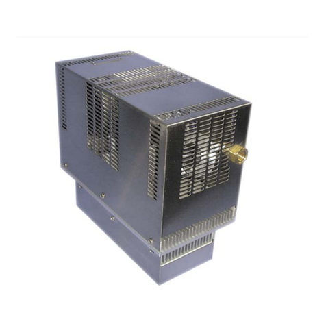
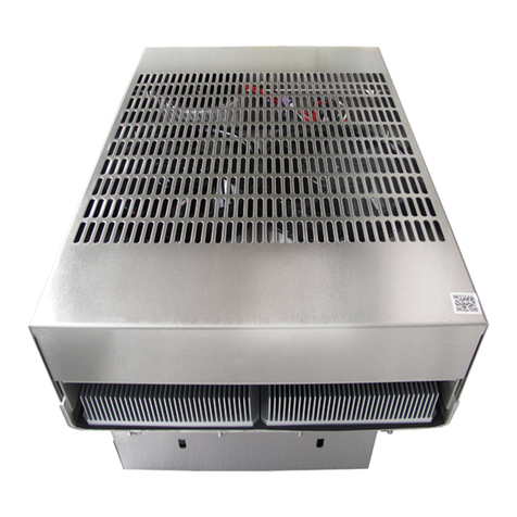
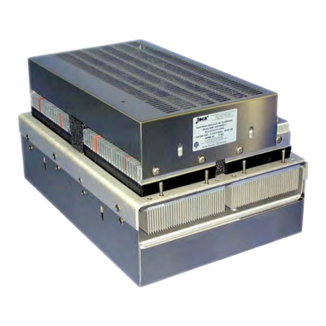
teca AHP-270FF User manual

ProductInformationPacket
ModelAHP-270FF
SolidStateAirConditioner
Nema-12,24VDC,WithTC-4FController
Part#0-L0J5-0-001
Thankyouforyourpurchase.Informationhasbeenenclosedregardingthe
installation,specifications,andwiringofyoursolid-stateassembly.
Pleasereadandfollowallinstructionscarefullybeforeinstallation.Onlyqualified
techniciansshouldinstallthisequipment.
Ifyouhaveanyquestionsregardingyourequipment,pleasedonothesitateto
callusat773-342-4900,andwewillbehappytoassistyou.Weareopenfrom
8:00am-4:30pmCentralTime.
Includedinthispacketyouwillfind:
InstallationNotesforAirConditioners
ProductLiteratureandSpecifications
AssemblyDrawing#SK140313
WiringDrawing#SK190511
InstallationDrawing#SK140314
InstallationGuide
WarrantyInformation

ImportantInstallationNotesforAir
Seal
Ambient
Air
Path
Enclosure
InternalAir
Path
MountingStyles:
Vertical(Side/Front/Back)Mounting:
CondensateRemovalSystem:
TopMounting:
Maintenance:
Cautions:
Notesoncondensation:
Both‘thrumount’and‘flushmount’unitscanbe
positionedinanyorientationandonanyenclosuresurface.Itisimportant
toconsiderinteriorairflowpatternswhendeterminingthemounting
location.Alsoofimportanceisanunrestrictedflowofambientairthru
thehotsideheatexchanger.Easeofaccessandinspectionmust
beconsideredforthoseapplicationsinparticularlysevere
environmentswhichmayrequireoccasionalmaintenance.
Verticalmountingreferstotheverticaldirectionofthecold
sideorinteriorfinsandisrecommendedforapplicationswith
highhumidity,poorandincompletecabinetsealsorany
conditionwhichmaycausethecoldsidefinstobemaintained
attemperaturesbelowthedewpointforlongperiodsoftime
allowingfortheformationofcondensation.Theverticalfin
directionprovidesadrippathwhereuponcondensationcanbe
collectedviaamoistureremovalsystem(standardonFHP-
units)oradrippanpositionedbelowthecoldsidefins.Drippansare
optionalforthrumountunits.
AllFHP-SeriesandAHP-1400airconditionerscontainabuilt-incondensateremovalsystem.Thecondensatekit
consistsofaantifungalspongewithacondensatewick.PVCtubingisalsoprovidedfordrainage.Drippansare
optionalforthrumountunitswhichmustbeevaluatedonanindividualbasis.Equationsdefiningarelationshipbetween
thecoldsidefinandenclosuretemperaturesareprovidedtoassistintheevaluation.
Thoughoftentheeasiestlocationtomountitisoftenthemostdifficulttoprotectfromcondensationinthisorientation
duetothefinorientation,gravityandanysusceptiblecomponentsbelow.Ifadrippanisemployedbytheenduseruse
cautiontoplacethepanfarenoughawayfromtheinternalfantominimizetherestrictionofairflow.Thepanshould
coverthefinendsaswellasthefanarea.Whenthereisachoice,theverticalorientationispreferredbymost
users.
Sincethetechnologyissolid-state,therearenofilters,compressors,orfluorocarbonstomaintain.Theonlymoving
partsarethefans.Itisrecommendedforharshordirtyenvironmentsthattheheatsinksbecleanedfromtimeto
time.ThiscanbeaccomplishedbydirectingcompressedairovertheexternalfinsoronNEMA4versionsbyhosing
theunitdown.Thiswillincreasetheoveralllifeandperformanceofthesystem.
Takecarewhenmountingnottodamagethesealbetweenthehotandcoldsidesinks.Donotattempttomountaunit
toawarpedsurfaceortrytomaketheunitsmountingsurfaceconformtoanunflatsurface.Donotpinchordamage
anyleadswhenmounting.Donotovertightenanyinstallationscrew,usereasonableforce.Alwaysmountwithany
condensatedraindown.Donotcompressthecoldsidebetweenthehotsideandanyothersurface.Donotobstruct
theairflowoneitherside.Whenmountingconsiderthenaturalairflowsoftheenclosure.Connectpoweronlyafterthe
installationiscomplete.
Condensationoccursat thecoldsidefinswhenthesurfacetemperaturegoesbelowthedewpoint.Toreduceor
removecondensate,considerthefollowing:
•RegulatetheFinTemperatureabovetheDewpoint.
•KeepEnclosureClosedandSealedfromOutsideHumidity.
•UseDesiccant(MoistureabsorbingGranules.)
•EmployCondensateRemovalSystem/DripPans.
Ifyouhaveanyquestionsregardingyourinstallation,Pleasefeelfreetocontactourtechnicaldepartmentforassistance
at773-342-4900.

TECA 1-888-TECA-USA (832-2872) www.thermoelectric.com
AHP-270 Air Conditioner / Heat Exchanger
Air Cooled 12 VDC, 24 VDC
Through Mounted 161 BTU/HR
Nema-12, 4, 4X
FEATURES
• Compact (only 6” X 4.75” X 6.6”)
• Mounts and operates in any orientation:
horizontal, vertical, etc.
• Lower vibration and noise
• No moving parts except fans
• Environmentally safe
• No compressor, fluorocarbons or filters
• Heat via reverse polarity
• Virtually maintenance-free operation
• Weight 4.4 LBS.
CONFIGURATIONS
INTEGRAL
MODEL PART NUMBER NOTES TEMPERATURE VOLTAGE CURRENT ENVIRONMENT
CONTROL VDC AMPS
AHP-270FFHC 0-L094-1-001* Industrial fans None 12 8.3 NEMA-12, IP 52
AHP-270FFHC 0-L095-1-001* Industrial fans None 24 4.1 NEMA-12, IP 52
AHP-270FF 0-L0J4-0-001 Industrial fans TC-4F 12 8.3 NEMA-12, IP 52
AHP-270FF 0-L0J5-0-001 Industrial fans TC-4F 24 4.1 NEMA-12, IP 52
AHP-270FFHC 0-L0I4-1-001 Industrial fans TC-7F 12 8.3 NEMA-12, IP 52
AHP-270FFHC 0-L0I5-1-001 Industrial fans TC-7F 24 4.1 NEMA-12, IP 52
AHP-270XEHC 0-L094-5-001* Industrial sealed HS fan None 12 8.3 NEMA-4, IP 56
AHP-270XEHC 0-L095-5-001* Industrial sealed HS fan None 24 4.1 NEMA-4, IP 56
AHP-270XE 0-L0J4-4-001 Industrial sealed HS fan TC-4F 12 8.3 NEMA-4, IP 56
AHP-270XE 0-L0J5-4-001 Industrial sealed HS fan TC-4F 24 4.1 NEMA-4, IP 56
AHP-270XEHC 0-L0I4-5-001 Industrial sealed HS fan TC-7F 12 8.3 NEMA-4, IP 56
AHP-270XEHC 0-L0I5-5-001 Industrial sealed HS fan TC-7F 24 4.1 NEMA-4, IP 56
AHP-270XHC 0-L094-3-001* Military grade HS fan None 12 8.3 NEMA-4X, IP 56
AHP-270XHC 0-L095-3-001* Military grade HS fan None 24 4.1 NEMA-4X, IP 56
AHP-270X 0-L0J4-2-001 Military grade HS fan TC-4F 12 8.3 NEMA-4X, IP 56
AHP-270X 0-L0J5-2-001 Military grade HS fan TC-4F 24 4.1 NEMA-4X, IP 56
AHP-270XHC 0-L0I4-3-001 Military grade HS fan TC-7F 12 8.3 NEMA-4X, IP 56
AHP-270XHC 0-L0I5-3-001 Military grade HS fan TC-7F 24 4.1 NEMA-4X, IP 56
* Heat/Cool function via reverse polarity capable external controller
Active Cooling 35 °C
Heat Exchanger (ECO-Mode) 25 °C
Active Heating 10 °C
Typical Hysteresis 5 °C
Operating Ambient -40/+70 °C
Operating Enclosure -10/+60 °C
CONTROL TEMPERATURES
Voltage 12 VDC, 24 VDC
Current, Active 8.3 AMPS, 4.1 AMPS
Current, ECO-Mode 0.3 AMPS
POWER INPUTS
Cooling (Traditional) 161 BTU/HR
Cooling (Din 3168) 47 WATTS
Cooling COP (at L35 L35) 0.47
Heating (Traditional) > 334 BTU/HR
Heating (Din 3168) > 98 WATTS
Heating COP > 1.0
PERFORMANCE RATINGS

www.thermoelectric.com 1-888-TECA-USA (832-2872) TECA
PERFORMANCE CURVE
Equation of Line: y=⌬T(°C) x=Capacity (Watts)
Ambient Temp 35°C 50°C
Enclosure Air y=1.02x-48.3 y=1.03x-51
Cold Sink y=0.78x-48.3 y=0.79x-51
AHP-270
Air Conditioner - Air Cooled
MOUNTING STYLE
Through Mounted
ENVIRONMENTS SERVED
NEMA-12 IP 52
NEMA-4,4X IP 56
RATING (TRADITIONAL)
161 BTU/hr @ 0 °F ⌬T
198 BTU/hr @ +20 °F ⌬T
RATING (DIN 3168)
47 Watts L35 L35
35 Watts L35 L50
DIMENSIONS
Air Flow Pattern


TC-4F/TC-7F with relays
inside the bracket
pre-wired to the unit
Loosen these screws
to slide the TC-4F/
TC-7F bracket out

TC-4F/TC-7F controller
inside the bracket
pre-wired to the AHP-250XE
Fit the AHP-250XE along with pre-wired TC-4F/TC-7F controller bracket
assembly through the mounting cutout on the enclosure. Making sure
wires are not pinched between the enclosure and the unit, secure the
AHP-250XE on the enclosure.

Slide the TC-4F/TC-7F
controller bracket under the
cold side fan finger guard
and re-tighten the two
screws to secure the bracket
in place.
After the installation of the AHP-250XE on the enclosure is complete, slide the TC-4F/TC-7F
bracket under the cold side fan finger guard and re-tighten the two screws.
Please note that on this guide the enclosure, mounting gasket and hardware are not shown.

Power Temperature Controllers
TECA 1-888-TECA-USA (832-2872) www.thermoelectric.com
MODEL PART NOTES TEMP @ TEMP @ T1-T2 RESET RESET TEMP @ T3 OPERATING SWITCHING SWITCHING
NUMBER NUMBER T1 °C T2 °C (MAX) °C (TYP) °C°C VOLTAGE VOLTAGE CURRENT MAX.
TC-6F 6F-00A-00-000 No Relay 35 +/- 5 25 +/- 5 10 +/- 3 6.5 3 Continuous On NA NA NA
TC-6F-AC 6F-03T-00-000 VAC Version 35 +/- 5 25 +/- 5 10 +/- 3 6.5 3 Continuous On 85-250 VAC 24-280 VAC 10
TC-6F-DC 6F-43D-00-000 12/24 VDC 35 +/- 5 25 +/- 5 10 +/- 3 6.5 3 Continuous On 12/24 VDC 0-100 VDC 20 ADC
TC-6F-DC 6F-33D-00-000 48 VDC 35 +/- 5 25 +/- 5 10 +/- 3 6.5 3 Continuous On 48 VDC 0-100 VDC 20 ADC
MODEL PART NOTES COOL HEAT RESET RESET OPERATING SWITCHING SWITCHING H-BRIDGE
NUMBER NUMBER TEMP. °C TEMP. °C (MAX) °C (TYP) °C VOLTAGE VOLTAGE CURRENT MAX. RELAYS
TC-3F-AC 3F-04R-00-000 VAC Version 35 +/- 5 15 +/- 5 6.5 3 85-280 VAC 24-280 VAC 10 AMPS N/A
TC-3F-DC 3F-44G-00-000 12/24 VDC 35 +/- 5 15 +/- 5 6.5 3 3.5-32 VDC 0-100 VDC 20 ADC N/A
TC-3F-DC 3F-44P-00-000 12/24 VDC 35 +/- 5 15 +/- 5 6.5 3 3.5-32 VDC 0-100 VDC 20 ADC Solid State
Model TC-6F (Cool Only) thermostat is designed using two temperature power switches in conjunction with a solid state relay. A three position
switch is provided to adjust temperature settings.
Model TC-3F (Heat/Cool) thermostat incorporates the same technology as the TC-6F. It contains a single setting each for both heating and
cooling as referenced below:
TC-1F POWER TEMPERATURE SWITCHES
Models TC-1F power temperature controller, with small tolerance and reset differential, are
the simplest and most cost effective way to control a cooling or heating device (VAC or VDC)
without a need for a relay. For circuits that have higher current draw simply use them in
conjunction with a solid state relay.
TC-6F COOL ONLY
TC-3F HEAT AND COOL
Part Numbers:
Mode Part Number Note
Cool TC-1C-XX switch closes on temperature rise
Heat TC-1H-XX switch closes on temperature drop
XX: Specify temperatures 20 °C, 25 °C, 30 °C, 35 °C for cool mode
and 10°C, 15 °C for heat mode
Example: TC-1C-20 and TC-1H-10
VOLTAGE CURRENT SET POINT T RESET
AMPS OLERANCE °CDIFFERENTIAL °C
125 VAC 2 +/- 3 3 - 6
250 VAC 1.3 +/- 3 3 - 6
12 VDC 2 +/- 3 3 - 6
24 VDC 1.3 +/- 3 3 - 6 Dimensions: Inches [Millimeters]
MODEL PART NOTES COOL HX HEAT RESET RESET OPERATING SWITCHING SWITCHING H-BRIDGE
NUMBER NUMBER TEMP. °C TEMP. °C TEMP. °C (MAX) °C (TYP) °C VOLTAGE VOLTAGE CURRENT MAX. RELAYS
TC-7F-DC 7F-24G-00-000 24 VDC 35 +/- 3 25 +/- 3 10 +/- 3 6.5 3 24 VDC 24 VDC 20 ADC N/A
TC-7F-DC 7F-24O-00-001 24 VDC 35 +/-3 25 +/-3 10 +/-3 6.5 3 24 VDC 24 VDC 12 ADC Solid State
TC-7F-DC 7F-24S-00-000 12 VDC 35 +/-3 25 +/-3 10 +/-3 6.5 3 12 VDC 12 VDC 20 ADC Solid State/Mechanical
TC-7F-DC 7F-24T-00-000 24 VDC 35 +/-3 25 +/-3 10 +/-3 6.5 3 24 VDC 24 VDC 20 ADC Solid State/Mechanical
TC-7F-DC 7F-24U-00-000 48 VDC 35 +/-3 25 +/-3 10 +/-3 6.5 3 48 VDC 48 VDC 20 ADC Solid State/Mechanical
Model TC-7F (Heat/Cool) thermostat incorporates the same technology as the TC-3F. It contains a single setting each for both heating and
cooling and a heat exchanger mode (ECO-Mode).
TC-7F HEAT/COOL WITH ECO-MODE
TC-4F COOL ONLY WITH ECO-MODE
Model TC-4F is simillar to TC-1F plus it has a 2nd power switch for heat exchanger mode (ECO-Mode). The active cool set point for TC-4F is 35 °C
and for heat exchanger mode (ECO-Mode) is 25 °C.
MODEL PART NOTES HX COOL RESET RESET OPERATING SWITCHING ACTIVE MODE ECO-MODE
NUMBER NUMBER TEMP. °C TEMP. °C (MAX) °C (TYP) °C VOLTAGE VOLTAGE SWITCHING SWITCHING
CURRENT MAX. CURRENT
TC-4F-DC 4F-24C-00-000 12/24/48 VDC 25 +/- 3 35 +/- 3 6.5 3 12/24/24 VDC 0-100 VDC 12 ADC 1.3 ADC
TC-4F-DC 4F-24D-00-000 12/24/48 VDC 25 +/- 3 35 +/- 3 6.5 3 12/24/48 VDC 0-100 VDC 20 ADC 1.3 ADC
TC-4F-DC 4F-24E-00-000 12/24/48 VDC 25 +/- 3 35 +/- 3 6.5 3 12/24/48 VDC 0-100 VDC 40 ADC 1.3 ADC
For custom variations of any of the controls, contact TECA.

LIMITEDWARRANTY
Intheeventadefectinmaterialorworkmanshipisdiscoveredinanyof
TECA’sproductswithinoneyearafterthedatetheyaredeliveredtoBuyer,
:(a)TECAisnotifiedofthedefectinwritingbycertifiedmailwithin14
daysofthedateofdiscovery;(b)TECAmaytheneither,atitssolediscretion,
inspecttheproductatBuyer’slocation,orrequirethattheproductbemade
availableatBuyer’sexpenseatTECA’spremisesforTECA’sinspectionwithin
14daysofthedateofnotification;and(c)theproductsaredefectiveandthe
defectsresultfromfaultymaterialsand/orworkmanshipandnotinanyway
fromaccident,misuse,misapplication,mishandling,modification,oralteration
bytheBuyerortheshipper,TECAshall,atitssoleoption,repairor
exchangedefectiveproductsfreeofchargetoBuyer,orcredittobuyerthe
priceofthedefectiveproducts.ALLOTHERWARRANTIES,EXPRESSOR
IMPLIED,AREEXCLUDED,INCLUDINGBUTNOTLIMITEDTOTHE
IMPLIEDWARRANTIESOFMERCHANTABILITYANDFITNESSFORA
PARTICULARPURPOSE.INNOEVENTSHALLTECABELIABLEFOR
ANYCLAIMBASEDUPONBREACHOFEXPRESSORIMPLIED
WARRANTYORANYOTHERDAMAGESWHETHERSPECIAL,INDIRECT,
INCIDENTAL,CONSEQUENTIAL,LOSTPROFITS,BUSINESS
INTERRUPTION,ORLOSSOFBUSINESSORCUSTOMER
RELATIONSHIPS.
Inordertoreturnmerchandiseforanyreason(repair,replacement,orcredit)
areturnauthorizationnumbermustbeissuedbyTECA.Newmerchandise
maynotbereturnedforcreditbeyond60daysfromshipment.Chargesfor
incidentalorotherdamagesmayalsobemade.Allreturnedgoodsmustbe
sentfreightprepaid.Arestockingchargeof15%willapply.Onspecial
equipmentandcustommodifiedequipmentorders,additionalincremental
cancellationchargesmaybemade.
andif
then
RETURNEDGOODS,RESTOCKINGCHARGES
This manual suits for next models
6
Table of contents
Other teca Air Conditioner manuals
teca
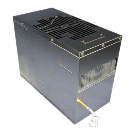
teca FHP-750XE User manual
teca
teca AHP-4200 Series User manual
teca
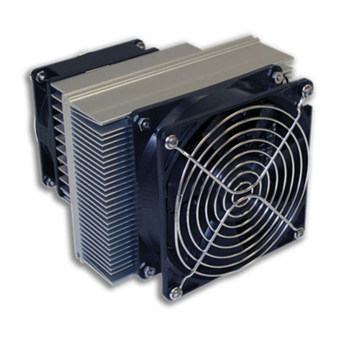
teca AHP-250FF User manual
teca
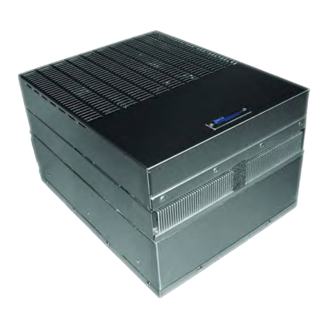
teca FHP-1501 Series User manual

teca
teca AHP-1201FF User manual
teca
teca AHP-1802XP User manual

teca
teca AHP-1801X User manual
teca
teca AHP-1200XP-1 User manual
teca
teca HP-1200FF User manual
teca
teca AHP-270 User manual
teca
teca AHP-250FFHC User manual
teca
teca FHP-250 Series User manual
teca
teca AHP-250XEHC User manual
teca
teca AHP-1800 Series User manual
teca
teca 0-018C-4-000 User manual
teca
teca IHP-2259XEHC Series User manual
teca
teca AHP-401 User manual
teca
teca AHP-1200FF User manual
teca
teca AHP-270XE User manual
teca
teca AHP-1501 User manual
