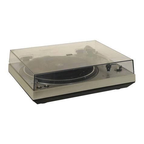
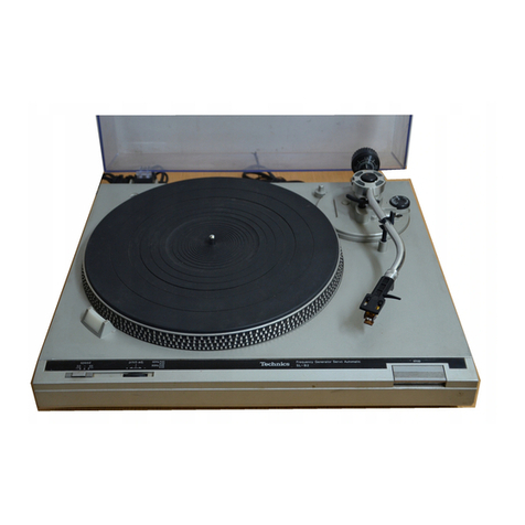
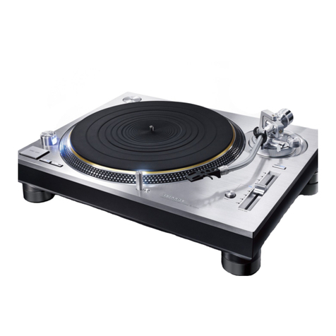
manuals.online logo
Brands
  1. Home
  2. •
  3. Brands
  4. •
  5. Technics
  6. •
  7. Turntable
  8. •
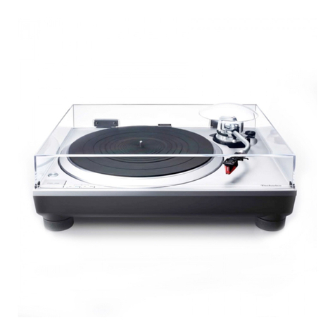
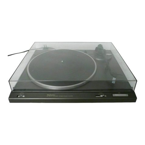
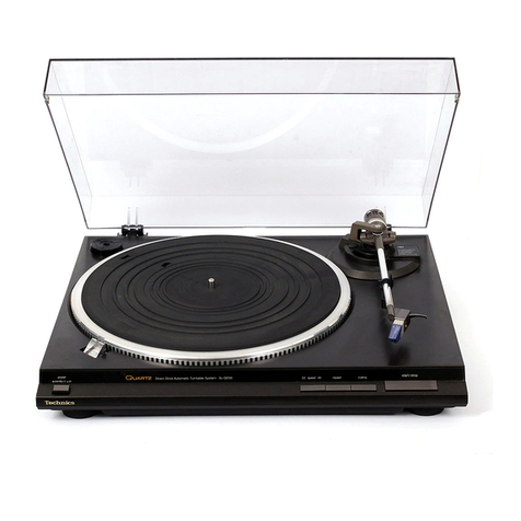
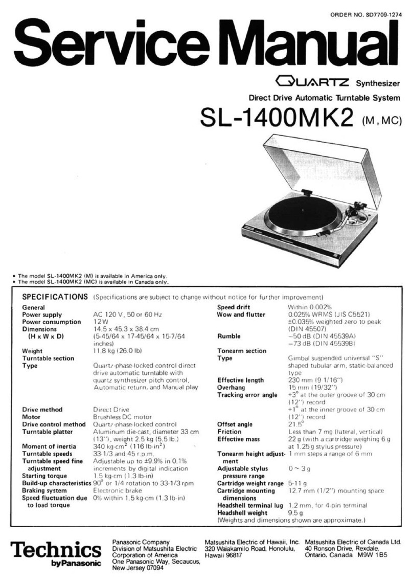
  9. Technics SL-DL5 User manual

Technics SL-DL5 User manual

This manual suits for next models

15

Other Technics Turntable manuals

Technics SL-1200GR User manual

Technics

Technics SL-1200GR User manual

Technics SL-1200M3D User manual

Technics

Technics SL-1200M3D User manual

Technics SL-MA1 User manual

Technics

Technics SL-MA1 User manual

Technics SL-B20 User manual

Technics

Technics SL-B20 User manual

Technics SL-1200MK2 User manual

Technics

Technics SL-1200MK2 User manual

Technics SL-1200MK2 User manual

Technics

Technics SL-1200MK2 User manual

Technics SL-D202 User manual

Technics

Technics SL-D202 User manual

Technics SL-1200MK2 User manual

Technics

Technics SL-1200MK2 User manual

Technics SL-1200GLD User manual

Technics

Technics SL-1200GLD User manual

Technics SL-1500 User manual

Technics

Technics SL-1500 User manual

Technics SL-1200MK2 Operating manual

Technics

Technics SL-1200MK2 Operating manual

Technics SL-Q303 User manual

Technics

Technics SL-Q303 User manual

Technics SL-1200GR User manual

Technics

Technics SL-1200GR User manual

Technics SL-Q3 User manual

Technics

Technics SL-Q3 User manual

Technics SL1210GREGK User manual

Technics

Technics SL1210GREGK User manual

Technics SL-Q33 User manual

Technics

Technics SL-Q33 User manual

Technics SL-1200G User manual

Technics

Technics SL-1200G User manual

Technics SL-DL1 User manual

Technics

Technics SL-DL1 User manual

Technics SL-1200GR User manual

Technics

Technics SL-1200GR User manual

Technics SL-1200M7L User manual

Technics

Technics SL-1200M7L User manual

Technics SL-1200MK2 Operating manual

Technics

Technics SL-1200MK2 Operating manual

Technics SL-J110R User manual

Technics

Technics SL-J110R User manual

Technics SL-1900 (M) User manual

Technics

Technics SL-1900 (M) User manual

Technics SL-220 User manual

Technics

Technics SL-220 User manual

Popular Turntable manuals by other brands

Trevi Mpv 1745 SD instructions

Trevi

Trevi Mpv 1745 SD instructions

Noblex NXC1039BT Service manual

Noblex

Noblex NXC1039BT Service manual

I.A.V. Piccolo owner's manual

I.A.V.

I.A.V. Piccolo owner's manual

JVC QL-Y5F Instruction book

JVC

JVC QL-Y5F Instruction book

Gemini CDT-05 MKII product manual

Gemini

Gemini CDT-05 MKII product manual

Rotel RP-820 owner's manual

Rotel

Rotel RP-820 owner's manual

Shuman MC-250BT user manual

Shuman

Shuman MC-250BT user manual

Stanton STR8-150 owner's manual

Stanton

Stanton STR8-150 owner's manual

Audio Technica AT-LPW40WN user manual

Audio Technica

Audio Technica AT-LPW40WN user manual

Crosley McQueen CR7011-GY instruction manual

Crosley

Crosley McQueen CR7011-GY instruction manual

auna TT-Classic Plus instruction manual

auna

auna TT-Classic Plus instruction manual

COMO AUDIO Turntable Analog user manual

COMO AUDIO

COMO AUDIO Turntable Analog user manual

Dual 1009 F owner's manual

Dual

Dual 1009 F owner's manual

AXIOMTEK OPS883-H Series Quick installation guide

AXIOMTEK

AXIOMTEK OPS883-H Series Quick installation guide

Pioneer PL-71 operating instructions

Pioneer

Pioneer PL-71 operating instructions

Vestax PDX-a1 owner's manual

Vestax

Vestax PDX-a1 owner's manual

Denon DP-400 owner's manual

Denon

Denon DP-400 owner's manual

Audio-Techica AT-LP60XBT user manual

Audio-Techica

Audio-Techica AT-LP60XBT user manual

manuals.online logo
manuals.online logoBrands
  • About & Mission
  • Contact us
  • Privacy Policy
  • Terms and Conditions

Copyright 2025 Manuals.Online. All Rights Reserved.

ORDER
NO.
SD82022117C2
Service
Manual
Direct
Drive
Automatic
Turntable
System
OL-DLS
ee
nee
[XL],
[EG],
i
BI,
[EF],
[XA],
[EH],
[Ei],
[EC]
SL-
DLS
(K)
,
[EH],
[XA]
Areas
(+
[E]
is
available
in
Switzerland
and
Scandinavia.
*
[EK]
is
available
in
United
Kingdom.
*
[XL]
is
available
in
Australia.
*
[EG]
is
available
in
F.R.
Germany.
*
[EB]
is
available
in
Belgium.
*
[EF]
is
available
in
France.
*
[XA]
is
available
in
Southeast
Asia,
Oceania,
Africa,
4
.
F
Middle
Near
East
and
Central
South
America.
*The
cabinet
and
dust
cover
are
available
in
black
color
and
silver
types.
*
[EH]
is
available
in
Holland.
*
The
black
type
model
is
provided
with
(K)
in
the
Service
Manual.
*
[Ei]
is
available
in
Italy.
es
[EC]
is
available
in
Czechoslovakia.
English
if,
H
Specifications
are
subject
to
change
without
notice
for
further
improvement.
Specifications
°°
oe
ee
:
Weight
and
dimensions
shown
are
approximate.
@
General
Turntable
speeds:
33-1/3
rpm
and
45
rpm
Power
supply:
220
V,
50/60
Hz
Auto
speed
select
Power
consumption:
10
W
(Manual
selection
possible)
Dimensions:
43
X
8,8
X
32,3
cm
Wow
and
flutter:
0.012%
WRMS"*
(WXHXD)
(16-59/64”"
3-1/2"
x
12-23/32")
0.025%
WRMS
(JIS
C5521)
43
X
34,1
X
32,3
cm
+0.035%
peak
(16-59/64"
*
13-27/64"
«
12-23/32")
(IEC
98A
Weighted)
(Maximum
height
when
top
*Measured
by
obtaining
signal
from
built-in
frequency
(dust
cover)
is
open.)
generator
of
motor
assembly.
Weight:
5
kg
(11
Ib.)
Rumble:
—56
dB
(IEC
98A
Unweighted)
—78
dB
(IEC
98A
Weighted)
Turntable
section
Type:
Direct
drive
Tonearm
section
Automatic
turntable
Type:
Dynamic
balanced
type
Auto
start/Auto
lead-in
Linear
tracking
tonearm
Auto
return
4-pivot
gimbal
suspension
Auto
stop
Effective
length:
10.5
cm
(4-1/8)
Repeat
play
Tracking
error
angle:
Within
+40.1°
Auto
speed
select
Effective
mass:
9 g
(including
cartridge)
Manual
speed
selection
possible
Resonance
frequency:
12
Hz
Auto
size
select
Tonearm
drive
motor:
DC
motor
Record
presence
detection
Phono
cable
Drive
method:
Direct
drive
capacitance:
150
pF
Motor:
Brushless
DC
motor
Drive
control
method:
—
F-G
servo
control
Cartridge
section
Turntable
platter:
Aluminum
die-cast
Type:
Moving
magnet
stereo
cartridge
Diameter
30
cm
(12”)
Magnetic
circuit:
All
laminated
core
‘Technics
Matsushita
Electric
Trading
Co.,
Ltd.
P.O.
Box
288,
Central
Osaka
Japan
Frequency
response:
Output
voltage:
Channel
separation:
Channel
balance:
Recommended
load
impedance:
Compliance
(dynamic):
10
Hz
~
30
kHz
20
Hz
~
10
kHz
+1
dB
2.5
mV
at
1
kHz,
5
cm/s.
zero
to
peak
lateral
velocity
(7
mV
at
1
kHz,
10
cm/s.
zero
to
peak
45°
velocity
[DIN
45
500])
22
dB
at
1
kHz
Within
2
dB
at
1
kHz
47
kQ~100
kQ
12
X 10°
cm/dyne
at
100
Hz
Stylus
pressure
range:
Weight:
Replacement
stylus:
1.25
+0.25
g
(12.5
+2.5
mN)
6.0
g
(cartridge
only)
EPS-24CS
*
The
product
for
destination
[XA]
is
equipped
with
voltage
selector.
*
Power
Supply:
240V,
50/60
Hz
For
United
Kingdom
and
Australia
({EK]
and
[XL]
areas)
Deutsch
TECHNISCHE
DATEN
Anderungen
der
technischen
Daten
vorbehalten.
Die
angegebenen
Gewichts-
und
Abmessungsdaten
sind
circa
Werte.
@
Allgemeine
Daten
@
Tonarm
Stromversorgung:
Leistungsaufnahme:
Abmessungen:
(BXHXT)
Gewicht:
Plattenspieler
Typ:
Antrieb:
Motor:
Antriebsregel-Methode:
Plattenteller:
Plattenteller-
Drehzahlen:
Gleichlaufschwan-
kungen:
220
V,
50/60
Hz
Wechselstrom
10
W
43
X
8,8
X
32,3
cm
43
X
34,1
X
32,3.cm
(Maximale
Hohe
bei
volistandig
gedffnetem
Gehauseoberteil.)
5kg
Direktangetriebener
automatischer
Plattenspieler
Auto-Start/Auto-Zufuhrung
Ruckfuhrautomatik
Stopp-Automatik
Wiederhol-Betrieb
Automatische
Drehzah!wahl
Manuelle
Drehzahlwah!
médglich
Automatische
Plattengr6Rewahl
Plattenprasenz-Registrierung
Direktantrieb
Kollektorloser
Gleichstrommotor
FG-Servo-Steuerung
Aluminium-DruckguB
Durchmesser
30
cm
33-1/3
und
45
U/min
Automatische
Drehzahiwahl
(manuelle
Wahi
moglich)
0,012%
WRMS*
0,025%
WRMS
(JIS
C5521)
+0,035%
Spitze
(IEC
98A
bewertet)
*“Gemessen
anhand
von
Signalen
vom
eingebauten
Fre-
quenzgenerator
des
Motorbauteils.
Rumpel-Fremd-
spannungsabstand:
Rumpel-Gerdusch-
spannungsabstand:
—56
dB
(IEC
98A
unbewertet)
~-78
dB
(IEC
98A
bewertet)
Typ:
Effektive
Lange:
Spurfehlwinkel:
Effektive
Masse:
Resonanzfrequenz:
Tonarm-Antriebsmotor:
Tonabnehmer
Typ:
Magnetkreis:
Frequenzgang:
Ausgangsspannung:
Kanaltrennung:
Kanalabweichung:
Empfohlene
Endimpedanz:
Nachgiebigkeit
(dynamisch):
Auflagekraft-
Einstellbereich:
Gewicht:
Ersatznadel:
Dynamisch
ausbalancierter
Tangential-Tonarm
mit
Kardan-
aufhangung
mit
4-Punkt-
Drehlager
10,5
cm
Innerhalb
+0,1°
9g
(einschlieBlich
Tonabnehmer)
12
Hz
Gleichstrommotor
Stereo-Magnet-Tonabnehmer
mit
Einpunkt-Aufhangungssystem
Ganzlamellenkern
10
Hz
bis
30
kHz
20
Hz
bis
10
kHz
+1
dB
2,5
mV
bei
1
KHz
5
cm/s.
Null-zu-Spitze,
lateral
{7
mV
bei
1
kHz
10
cm/s.
Null-
zu-Spitze,
45°
(DIN
45
000)]
22
dB
bei
1
KHz
Innerhalb
2
dB
bei
1
kHz
47
kQ
~
100
kQ
12
x
10
"cm/dyn
bei
100
Hz
1,25
40,25
g
(12,5
+2,5
mN)
6,0
g
(nur
Tonabnehmer)
EPS-24CS
Francais
CARACTERISTIQUES
@
Généralités
Alimentation:
Consommation:
Dimensions:
(LXHXP)
Poids:
Platine
de
lecture
Type:
Systeme
d’entraine-
ment:
Moteur:
Systéme
de
commande:
dentrainement:
Plateau
de
lecture:
Vitesses
de
la
platine:
Pleurage
et
scintille-
ment:
Espafiol
220
V,
50/60
Hz
10
W
43
X
8,8
X
32,3
cm
43
X
34,1
X
32,3
cm
(Hauteur
maximum
lorsque
le
dessus
(couvercle
protege-
poussiere)
est
ouvert.)
5
kg
Entrainement
direct
Platine
automatique
Départ
automatique/Entrée
automatique
Retour
automatique
Arrét
automatique
Auditon
répetée
Sélection
de
vitesse
automatique
Sélection
automatique
du
diamétre
Sélection
de
vitesse
manuelle
possible
Détection
de
la
présence
d'un
disque
Entrainement
direct
Moteur
C.C.
sans
balai
Générateur
de
frequences
a
servo-commande
Aluminium
moulé
sous
pression
Diametre
30
cm
33-1/3
et
45
t/p.m.
Sélecteur
de
vitesse
automatique
(Sélection
manuelle
possible)
0,012%
de
valeur
efficace*
0,025%
de
valeur
efficace
(JIS
C5521)
+0,035%
de
créte
(IEC
98A
Pondére)
Les
spécifications
sont
susceptibles
d‘étre
modifiées
sans
préavis.
Le
poids
et
les
dimensions
donnés
sont
approximatifs.
*
Mesuré
par
l'obtention
d'un
signal
provenant
du
généra-
teur
de
frequences
incorporé
de
l'ensemble
du
moteur.
Ronflement:
—56
dB
(IEC
98A
Non
pondéré)
—78
dB
(IEC
98A
Pondéré)
Bras
de
lecture
Type:
Bras
de
lecture
d'alignement
linéaire
de
type
a
équilibre
dynamique
avec
suspension
a
la
cardan
a
4
pivots
Longueur
effective:
105
mm
Angle
d’erreur
de
piste:
En
deca
de
+0,1°
Masse
réelle:
9g
(y
compris
la
cellule
pick-up)
Fréquence
de
résonance:
12
Hz
Moteur
d’entrainement
du
bras
de
lecture:
Cellule
pick-up
Type:
Cellule
pick-up
stéréo
a
aimant
mobile
Circuit
magnétique:
Noyau
entiérement
feuilleté
Réponse
en
fréquence:
10
Hz
a
30
kHz
20
Hz
a
10
kHz
+1
dB
2,5
mV
a1
kHz;
5
cm/s.
zéro
a
vitesse
latérale
de
créte
(7
mV
a1
kHz;
10
cm/s.,
zéro
a
vitesse
45°
de
créte
[DIN
45
000))
Séparation
des
canaux:
22
dB
a1
kHz
Equilibrage
des
canaux:
En
deca
de
2
dB
a1
kHz
impédance
de
charge
recommandeée:
47
kQ~100
kQ
Elasticité
(dynamique):
12
x
10°
cm/dyne
a
100
Hz
Plage
de
la
force
verticale
d’appui:
1,25
+0,25
g
(12,5
+2,5
mN)
Poids:
6,0
g
(cellule
seule)
Remplacement
de
la
pointe
de
lecture:
Moteur
C.C.
Tension
de
sortie:
EPS-24CS
Velocidades
del
plato
giratorio:
33-1/3
y
45
rpm
Seleccion
automatica
de
la
velocidad
(También
posibilidad
de
seleccionar
a
mano)
Ululaciones
y
trémolo:
.
0,012%
WRMS”*
0,025%
WRMS
(JIS
C5521)
+0,035%
cresta
(IEC
98A
Ponderado)
*Medido
obteniendo
una
sefial
proveniente
del
generador
de
frecuencias
incorporado
del
conjunto
del
motor.
Ruido
de
rodadura:
—56
dB
(IEC
98A
No
ponderado)
—78
dB
(IEC
98A
Ponderado)
Seccidon
del
brazo
sonoro
Tipo:
Brazo
sonoro
de
seguimiento
lineal
de
tipo
con
equilibrio
dinamico
con
suspension
cardanica
de
4
pivotes
Longitud
efectiva:
10,5
cm
Angulo
de
error
de
seguimiento:
Masa
efectiva:
Frecuencia
de
resonancia:
12
Hz
Motor
de
accionamiento
del
brazo
sonoro:
tnferior
a
+0,1°
aproxim.
9
g
(incluyendo
el
cartucho)
Motor
de
corriente
continua
m@
CONTENTS
Page
LOCATION
OF
CONTROLS...
.......
22.0.
eee
4,5
DISASSEMBLY
INSTRUCTIONS
................
6~8
HOW
TO
SET
THE
TONEARM
DRIVE
ROPE............
9
CHECKING
METHOD
OF
THE
UNIT......
Rae
eee
eee
D
MEASUREMENTS
AND
ADJUSTMENTS
(English).
. .
.
.10~12
MESSUNGEN
UND
JUSTIERUNGEN
(Deutsch)
.......13,14
MESURAGES
ET
REGLAGES
(Frangais)............
15,
16
MEDICIONES
Y
AJUSTE
(Espafiol)...........000-
17,18
REPLACEMENT
PARTS
(Electric
Parts)
..............
19
m@
LOCATION
OF
CONTROLS
@
Seccion
del
cartucho
Tipo:
Cartucho
estereofénico
de
iman
movil
Circuito
magnético:
Nucleo
totalmente
laminado
Respuesta
de
frecuencia:
10
Hz
a
30
kHz
20
Hz
a
10
kHz
+1
dB
2.5
mV
a1
kHz
Velocidad
lateral
de
cero
a
cresta
de
5
cm/s
(7
mV
a1
kHz.
Velocidad
de
45°
de
cero
a
cresta
de
10
cm/s
[DIN
45
000})
Separacién
de
canales:
22
dB
a1
kHz
Equilibrio
de
canales:
Inferior
a
2
dB
a
1
kHz
Impedancia
de
carga
recomendada:
Elasticidad
(dinamica):
Radio
de
presién
de
la
aguja:
1,25
+0,25
g
(12,5
+2,5
mN)
Peso:
6
g
(cartucho
solamente)
Aguja
de
recambio:
EPS-24CS
Voltaje
de
salida:
47
kQ
a
100
kQ
12
X
10°
cm/dina
a
100
Hz
Page
TIMING
CHART.....
Sve
eae
a
eae
ba
Gette:
cae
She
tastates
eeteite
els
20
BLOCK
DIAGRAM.
.............
2.2000
eeeee
21,22
CIRCUIT
BOARD
AND
WIRING
CONNECTION
DIAGRAM...
..
wee
ee ee
23,
24
SCHEMATIC
DIAGRAM
.........
000
ee
een
anee
25,
26
EXPLODED
VIEWS
.........2
0000
eeu
eeae
.
.27,29
REPLACEMENT
PARTS
LIST
(Cabinet
and
Chassis
Parts)...........0.0ee
eevee
29
PACKINGS
iech
go
ease
ais
eek
tetas
8
Sa
ek
ee
8,
Suk
aa
30
Las
especificaciones
quedan
sujetas
a
cambios
sin
aviso
previo.
Los
peso
y
las
dimensiones
indicados
son
aproximados.
Seleccién
automatica
de
la
velocidad
Es
posible
seleccionar
la
Record
groove
scale
ESPECIFICACIONES
@
En
general
Alimentacion
de
corriente:
Upper
cabinet
(Dust
cover)
Tonearm
position
220
V,
50/60
Hz
indicator
LED
Consumo
de
corriente:
10
W
velocidad
a
mano
Bags
Dimensiones:
43
X
8,8
X
32,3
cm
Seleccion
automatica
(Ancho
XAlto
XProf.)
43
*
34,1
X
32,3
cm
del
tamano
(Altura
maxima
cuando
la
parte
Deteccién
de
presencia
de
disco
de
arriba
(tapa
contra
e!
polvo)
Método
de
acciona-
esta
abierta.)
miento:
Accionamiento
directo
Peso:
5kg
Motor:
Motor
de
corriente
continua
sin
-
F
escobillas
@
Seccidn
del
plato
giratorio
Método
de
control
Tipo:
Accionamiento
directo
de
accionamiento:
Servocontrol
por
generador
Z
Plato
giratorio
automatico
de
frecuencias
Sn
Stop
ewiteh
ff
switch
Platillo
del
plato
Ni
c
giratorio:
Aluminio
fundido
30
cm
de
diametro
Start
switch
Arranque
automatico/
Comienzo
automatico
Retorno
automatico
Parada
automatica
Ejecucion
repetida
Cueing
control
Repeat
switch/indicator
Remote
control
jack
Phono
output
terminals
Ground
Tonearm
drive
motor
Record
size
detection
lever
Record
detector
Turntable
mat
Phono
output
terminal
Cabinet
switch
Remote
controi
jack
Turntable
drive
IC
Operation
amplifier
IC
Micro
computer
IC
*The
product
for
destination
[XA]
is
equipped
with
voltage
selector.
™
DISASSEMBLY
INSTRUCTIONS
Voltage
selector
(110V
—
120V/220V
—
240V)
AC
input
socket
Stylus-pressure
adjustment
screw
Cabinet
switch
Center
spindle
45
rpm
adaptor
oe
Speed
selector
AC
input
socket
Record
size
detection
switch
Voltage
selector
circuit
(Product
for
[XA]
only)
Power
transformer
Power
source
fuse
P.C.B.
On/off
switch
(Power)
[5]
Hon
@
1.
2.
3.
4,
.
When
putting
the
turntable
mat
on
the
turntable,
match
.
Remove
the
bottom
board.
:
.
Release
the
holder
of
the
stator
.
Remove
the
2
setscrews
(Fig.
4
:
.
Remove
the
3
setscrews
(Fig.
4:
How
to
remove
the
turntable
e
How
to
remove
the
bottom
board
.
Open
the
upper
cabinet.
1.
Remove
the
45
rpm
adaptor
and
turntable.
.
Detach
the
45
rpm
adaptor
as
shown
in
Fig.
1.
2.
Turn
over
the
body
on
a
soft
cloth
taking
care
not
to
.
Remove
the
turntable
mat
and
lift
up
the
turntable.
damage
the
upper
cabinet
and
dust
cover.
*The
turntable
is
tight
fitted
onto
the
center
spindle.
3.
Remove
the
6
setscrews.
(Fig.
3:
@9~@)
When
removing
the
turntable,
take
care
not
to
give
damage
to
the
upper
cabinet
arm
motor
cover
and
e
tonearm
cover.
@
the
projection
of
the
turntable
(record
detector)
with
f
the
hold
of
the
turntable
mat.
(See
Fig.
2)
°
oO
Cc
Turn
counterclockwise
Turntable
mat
f
fngulator
and
lift
up.
!
Spring
Record
detector
How
to
remove
the
main
circuit
printed
board
Remove
the
bottom
board.
(Refer
to
‘“‘How
to
remove
the
bottom
board”.)
Release
the
holder
of
the
stator
frame
lead
connector
and
pull
off
the
lead
wire.
(Fig.
4)
Remove
the
6
setscrews
(Fig.
4:
@
~
@)
of
the
printed
circuit
board.
When
mounting
the
printed
circuit
board.....
(1)
Turn
the
record
detecting
sensor
lever
counterclockwise.
(2)
Insert
the
speed
selector
switch
into
the
knob.
(3)
Connect
the
lead
wire
to
the
connector,
close
the
holder
and
tighten
the
screws.
*The
printed
circuit
board
‘is
grounded
to
the
chassis
by
screw
@
.
When
checking
the
conduction
with
screw
@
removed,
connect
the
earth
terminal
of
the
printed
circuit
board
to
the
chassis
(stator
frame).
How
to
remove
the
stator
frame
(Refer
to
“How
to
remove
the
bottom
board”.)
Main
printed
wa
circuit
board
frame
sead
connector
and
pull
of
Speed
selector
the
lead
wire.
(Fig.
4)
switch
Turn
C
counterclockwise
®
,
®
)
of
the
radiator.
r=
wa
Record
ra
detector
lever
®
~
@)
of
the
stator
frame.
F®
NO
oh
WN
.
Remove
the
5
setscrews
of
the
dust
cover.
.
Remove
the
bottom
board.
.
Remove
the
turntable.
How
to
remove
the
dust
cover
.
Open
the
upper
cabinet.
.
Remove
the
4
setscrews
of
the
arm
motor
cover.
(Fig.
5:@
~@).
(Fig.
5
:
@
~@
and
Fig.
6:@,@)
®
Sy
°@
®
Fig.
6
How
to
remove
the
upper
cabinet
(Separation
of
cabinet)
(Refer
to
“How
to
remove
the
bottom
board”.)
.
Detach
the
output
terminal
from
lower
cabinet.
(Fig.
7)
.
Pull
out
connectors
@
and
@
.
(Fig.
7)
.
Remove
the
4
setscrews
of
the
hinge.
(Fig.
7:@
~
@)
.
The
hinge
is
engaged
with
the
lower
cabinet.
The
lower
cabinet
can
be
separated
from
the
upper
cabinet
by
lifting
the
cabinet
while
releasing
the
hinge
claws.
{See
Fig.
5
(A))
How
to
remove
the
arm
motor
printed
board
.
Open
the
upper
cabinet
and
detach
the
arm
motor
cover.
(Refer
to
“How
to
remove
the
dust
cover’’.)
.
Remove
the
setscrews
@).
(Fig.
5)
.
Release
the
claws
with
the
nail
and
remove
the
position
detecting
circuit
and
the
rest
switch.
(Fig.
5
:
(B),
(C))
How
to
remove
the
Hall
element
(Refer
to
“How
to
remove
the
turntable’’
)
.
Unsolder
the
Hal!
element.
*The
Hall
element
should
be
installed
with
the
marking
side
up
asin
Fig.
8.
With
the
marking
side
up,
no
problem
will
occur
even
when
the
leg
is
reversed
in
position.
®
e
1
2
3
e
1
2
(A)
Release
fS
Upper
cabinet
{Dust
cover)
(B)
Release
af
exas
Re
Position
\
detecting
~
circuit
Rest
switch
Fig.
5
@F
'
®
|
Main
printed
'
%@
circuit
board
SS
Output
tera
Ss
e
1
2
<a
6
Lower
cabinet
3
H2
Marking
Stator
board
Fig.
8
<\
H1
Marking
.
Remove
the
cartridge.
How
to
remove
the
cartridge
.
Open
the
upper
cabinet.
.
Completely
loosen
the
setscrew
and
pull
out
the
car-
tridge.
(Fig.
9)
.
When
attaching
the
cartridge
again,
match
the
tonearm
connector
with
the
cartridge
pin,
then
completely
insert
it
and
tighten
the
setscrew.
How
to
remove
the
tonearm
(Refer
to
‘“‘How
to
remove
the
cartridge’’.)
.
Remove
the
3
setscrews
of
the
tonearm
cover
(Fig.
5
:
@®
~
@®
)
and
detach
the
cover
in
the
direction
of
the
arrow.
.
Unsolder
5
leads
of
the
cartridge.
(Fig.
10)
.
Remove
the
setscrew
of
the
tonearm
board.
(Fig.
10
:
@
)
.
Remove
the
setscrew
of
the
tonearm.
(Fig.
11:
@)
Lead
(Indicator)
Tonearm
position
indicator
board
(Cartridge)
Fig.
10
How
to
remove
the
cabinet
switch
.
Remove
the
bottom
board.
(Refer
to
“How
to
remove
the
bottom
board’’.)
.
Remove
the
setscrew
of
the
cabinet
switch.
(Fig.
12
:
@)
.
When
fitting
the
cabinet
switch,
be
sure
to
open
the
upper
cabinet.
Lower
cabinet
Fig.
9
e
How
to
remove
the
cueing
control
ass’y
1.
Remove
the
cartridge.
(Refer
to
“How
to
remove
the
cartridge’’.)
2.
Remove
the
tonearm
cover.
the
tonearm’)
3.
Unsolder
2
leads
of
the
plunger.
4.
Remove
the
2
setscrews
of
the
cueing
control
ass‘y.
(Fig.
10:
@,@)
(Refer
to
“How
to
remove
e
How
to
remove
the
tonearm
position
indicator
board
1.
Remove
the
cartridge.
cartridge’’.)
2.
Remove
the
tonearm
cover.
(Refer
to
“How
to
remove
the
tonearm.)
.
Unsolder
2
leads
of
the
indicator.
(Fig.
10)
4.
Remove
the
setscrew
of
the
tonearm
position
indicator
board.
(Fig.
10:
@)
(Refer
to
“How
to
remove
the
Ww
Tonearm
e
How
to
remove
the
on/off
switch
1.
Remove
the
bottom
board.
(Refer
to
‘“‘How
to
remove
the
bottom
board”’.)
2.
Pull
out
the
knob.
3.
Remove
the
setscrew
of
the
on/off
switch.
(Fig.
13:
@)
fe
“On/oft”
switch
Knob
Fig.
13
m
HOW
TO
SET
THE
TONEARM
DRIVE
ROPE
Set the
rope
according
to
the
following
procedure.
1.
Open
the
upper
cabinet
and
remove
the
cartridge.
2.
Remove
the
arm
motor
cover
and
tonearm
cover.
®
3.
Detach
the
arm
drive
wheel
“C’"
ring
@
and
washer
@
,
and
remove
the
drive
wheel.
(See
Fig.
14)
A.
Turn
over
the
arm
drive
wheel
and
set
the
rope
in
the
orderof1
~
2.
(Fig.
15)
5.
Holding
the
rope
set
over
the
arm
drive
wheel
with
the
hand,
set
the
tope
over
the
wheels
in
the
order
of
3
~
5
in
Fig.
16.
6.
After
setting
the
rope,
rotate
the
worm
gear
by
hand
until
the
tonearm
matches
the
rope
connector.
7.
Rotate
the
worm
gear
by
hand
and
check
that
the
tonearm
operates,
and
then
fit
the
washer
@
and
“C”
ring
@
in
place.
a
Drive
Wheel
a
4th
groove
Fig.
14
©)
Connector
1
2nd
groove
Connector
Fig.
15
Worm
gear
Fig.
16
m
CHECKING
METHOD
OF
THE
UNIT
The
unit
(circuit,
etc.)
can
be
checked
and
adjusted
as
follows:
©
Close
the
upper
cabinet.
(Check
of
the
main
circuit
printed
board.)
1.
Remove
the
bottom
board.
2.
Place
the
unit
on
the
player
repair
table.
(Fig.
17)
3.
Put
arecord
on
the
turntable
and
close
the
upper
cabinet.
4.
Set
the
power
on/off
switch
to
‘‘on”.
5.
Press
the
start
button
to
rotate
the
turntable.
6.
Check
the
unit
with
a
tester
from
below
the
bottom.
e
Open
the
upper
cabinet.
(Check
of
the
tonearm
drive
unit
and
main
circuit
printed
board.)
1.
Remove
the
bottom
board.
2.
Completely
open
the
upper
cabinet.
3.
Secure
the
record
detector
with
adhesive
tape.
(Fig.
18)
4.
Fasten
the
cabinet
release
switch
with
adhesive
tape.
(Fig.
19)
5.
Place
the
unit
on
the
player
repair
table
(Fig.
20)
or
carefully
raise
the
unit
after
removing
the
45-adaptor
and
turntable
mat.
(Fig.
21).
Set
the
power
on/off
switch
to
“on”.
7.
Press
the
start
button.
(The
record
size
17
cm
and
the
speed
45
r.p.m.
are
automatically
detected,
and
the
turntable
starts
rotating.)
*
When
raising
the
unit,
take
care
because
the
turntable
is
not
secured.
It
is
desirable
to
use
the
player
repair
table.)
cord
|
71
|
|
Press
the
switch
with tape
Repair
table
Fig.
18
Record
detector
Fig.
17
Press
it
with
tape
Repair
table
Fig.
19
Fig.
20
(Abb.
1)
)
*
Take
care
not
to
allow
the
unit
to
falle
down.
Main
printed
Nq
*
It
is
desirable
to
use
a
repair
table
for
the
repair
job.
circuit
board
Fig.
21
m@
MEASUREMENTS
AND
ADJUSTMENTS
aoe
English
a
e
Diagram
for
printed
circuit
board
adjustment
Clock
frequency
adjustment
45r.p.m.
adjustment
33r.p.m.
adjustment
*
Connect
between
03
€)
and
IC301
for
clock
frequency
adjustment.
*
Zwischen
Q3
©)
und
1C301
anschlieGen,
fiir
die
Zeitgeberfrequenz.
*
Connecter
entre
Q3
€)
et
1C301
pour
le
réglage
de
la
fréquence
des
impulsions
d’horloge.
*Conectar
entre
Q3
©
y
1C301
para
ajuste
de
frecuencia
de
reloj.
e
Instruments
used
1.
DC
voltmeter
2.
Oscilloscope
or
frequency
counter
Auto
start
position
Arm
lift
height
Adjustment
procedure
1
Make
sure
that
the
tonearm
is
at
the
start
position
{on
the
rest).
2
Adjust
by
turning
the
auto
start
position
adjusting
screw,
Tonearm
lowers
inside
the
disc:
Turn
the
adjusting
screw
clockwise.
Tonearm
lowers
outside
the
disc:
Turn
the
adjusting
screw
anticlockwise.
*
Be
sure
to
use
30
cm
record
for
the
adjustment.
Adjusting
screw
[Rear
of
set]
———>
Make
the
set
as
illustrated
in
Fig.
20.
Set
the
on/off
switch
to
‘‘on”
and
press
the
start
switch
to
shift
the
tonearm
inward.
Press
the
cueing
control
button
so
that
the
distance
between
the
cartridge
stylus
tip
and
the
guide
rail
is
27.7
mm.
To
increase
the
distance
turn
the
adjusting
screw
anticlockwise.
To
decrease
the
distance
/
Cartridge
Adjusting
screw
Tonearm
offset
angle
Make
the
set
as
illustrated
in
Fig.
20.
2
Set
the
on/off
switch
to
“on”
and
press
the
start
switch
to
shift
the
tonearm
inward.
Turn
the
offset
angle
adjusting
screw
so
that
the
arm
center
matches
the
V-
groove
of
the
lift
bar.
Adjusting
screw
Step
Item
Adjustment
procedure
4
Servo
gain
and
offset
1
Make
the
set
as
illustrated
in
Fig.
20.
voltage
2
Connect
the
DC
voltmeter
to
TP315
(Q306)
base
or
connector
CN301
terminal
@)
and
TP3
(earth).
3
Set
the
on/off
switch
to
“on”
and
press
the
start
switch
to
shift
the
tonearm
inward.
4
Remove
the
label
of
the
tonearm
cover.
5
Completely
shift
the
tonearm
to
the
right.
Then,
adjust
VR501
so
that
the
voltage
is
3.6V.
(Servo
gain
adjustment)
6
Set
the
tonearm
to
the
center
and
make
sure
that
the
output
voltage
is
1.8V.
If
the
voltage
is
not
1.8V,
loosen
the
printed
circuit
board
setscrew
and
move
the
board
to
the
right
of
left
by
a
screwdriver
so
that
the
output
voltage
becomes
1.8V.
After
the
adjustment,
tighten
the
printed
circuit
board
setscrew..
(Offset
adjustment)
Center
(1.8V)
o~
(“Clockwise
(3.6V)
sera
Gord
ses
a
driver
“ou
\
é
<I
EP
ee
/
Label
G7
)
\
wk,
5
Clock
frequency
1
Make
the
set
as
illustrated
in
Fig.
20.
Ls
LS)
Remove
the
tape
from
the
cabinet
switch.
3
Connect
TP7
(Q3
emitter)
to
TP326
(1C301
pin
14)
with
clip
lead
or
the
like.
4
Connect
the
oscilloscope
or
frequency
counter
to
TP316
(1C301
pin
4).
Set
the
on/off
switch
to
“on”.
6
Adjust
VR301
so
that
the
output
waveform
cycle
is
40
us
t
2
us.
Also,
adjust
VR301
so
that
the
output
frequency
is
25
kHz
+
1.25
kHz.
oa
40us
+
2us
Frequency:
25
kHz
+
1.25
kHz
Rotational
speed
1
Make
the
set
as
illustrated
in
Fig.
20.
2
Play
a
17
cm
record.
3
Turn
VR202
to
adjust
the
speed
to
the
rated
speed
(45
rpm).
4
Play
a
30
cm
record.
5
Turn
VR201
to
adjust
the
speed
to
the
rated
speed
(33-1/3
rpm).
Note:
Be
sure
to
adjust
45
rpm
first.
m
MESSUNGEN
UND
JUSTIERUNGEN
sees
Deutsch
see
e
Zu
verwendende
Instrumente
1.
Elektronisches
Gleichstrom-Voltmeter
2.
Oszilloskop
oder
Frequenzzahler
Schritt
Gegenstand
Justiermethode
Auto-Start-Position
1
Uberpriifen,
da&
der
Tonarm
in
der
Startposition
(auf
der
Tonarmablage)
ist.
2
Durch
Drehen
der
Auto-Start-Positions-
Justierschraube
justieren.
Bei
Absenken
des
Tonarms
zu
weit
innen:
Die
Justierschraube
im
Uhrzeigersinn
drehen.
Bei
Absenken
des
Tonarms
zu
weit
auBen:
Die
Justierschraube
entgegen
dem
Uhrzeigersinn
drehen.
(Gerdterickseite)=——>
_
*Fir
die
Justierung
mu
unbedingt
eine
30
cm-
Platte
verwendet
werden.
Justierschraube
=
Tonarm-lifthdéhe
1
Das
Gerat
so
einstellen,
wie
in
Abb.
1
gezeigt.
2
Den
Netzschalter
auf
ON
stellen
und
die
Starttaste
driicken,
um
den
Tonarm
nach
innen
zu
bewegen.
3
Die
Lifttaste
driicken,
so
da&
der
Abstand
zwischen
der
Tonabnehmer-Nadelspitze
und
der
Fiihrungsschiene
27.7
mm
betragt.
Um
den
Abstand
zu
vergroBern....
die
Justierschraube
entgegen
dem
Uhrzeigersinn
drehen.
Um
den
Abstand
zu
verkleinern....
die
Justierschraube
im
Uhrzeigersinn
drehen.
Tonabnehmer
Justierschraube
Tonarm-Reibungs-
winkel
Das
Gerat
so
einstellen,
wie
in
Abb.
1
gezeigt.
Den
Netzschalter
auf
ON
stellen
und
die
Starttaste
driicken,
um
den
Tonarm
nach
innen
zu
bewegen.
Die
Reibungswinkel-Justierschraube
drehen,
bis
die
Armmitte
mit
der
Justierschraube
V-Kerbe
am
Liftbalken
itbereinstimmt.
Gegenstand
Justiermethode
Servo-Verstarkungs-
und
Kompensations-
Spannung
Das
Gerat
so
einstellen,
wie
in
Abb.
1
gezeigt.
Das
elektronische
Gleichstrom-Voltmeter
an
TP315
(Q306)
Basis
oder
Anschlu8
CN301
Stift
2
und
TP3
(Masse).
Den
Netzschalter
auf
ON
stellen
und
die
Starttaste
driicken,
um
den
Tonarm
nach
innen
zu
bewegen.
Den
Tonarm
ganz
nach
rechts
stellen.
VR501
dann
so
einstellen,
da&
die
Spannung
3.6V
betragt.
(Servo-Verstarkungs-Justierung)
Den
Tonarm
in
die
Mitte
stellen
und
iiberpriifen,
da&
die
Ausgangsspannung
1.8V
betragt.
Falls
die
Spannung
nicht
1.8V
betragt,
die
Platinen-Befestigungsschraube
Idsen
und
die
Platine
mit
einem
Schraubenzieher-
nach
links
oder
rechts
bewegen,
bis
die
Ausgangsspannung
1.8V
betragt.
Nach
der
Justierung,
die
Platinen-Befestigungs-
schraube
wieder
festdrehen.
Mitte
(Kompensationsspannungs-Justierung)
(1.8V)
(~~)
Uhrzeigersinn
Platinen-Befestigungsschraube
(3.6V)
>
Schraubenzieher
——,
Entfernen
sie
die
Etikette
DB
[VR501
Zeitgeberfrequenz
Drehzahl
Das
Gerat
so
einstellen,
wie
in
Abb.
1
gezeigt.
Das
Klebband
vom
Gehdauseschalter
entfernen.
Mit
einem
Klemmenkabel
0.4.
TP7
(Q3
Emitter)
mit
TP326
(1C301
Stift
14)
verbinden.
Das
Oszilloskop
oder
den
Frequenzzahler
an
TP316
(1C301
Stift
4)
anschlieBen.
Den
Netzschalter
auf
ON
stellen.
VR301
so
justieren,
da&
der
Ausgangswellenform-
Zyklus
40us
+
2us
betragt.
Ebenfalls
VR301
so
justieren,
da&
die
Ausgangsfrequenz
25
kHz
+
1.25
kHz
betragt.
40us
*
2us
Frequenz:
25
kHz
+
1.25
kHz:
Das
Gerat
so
einstellen,
wie
in
Abb.
1
gezeigt.
VR202
Eine
17
cm-Platte
abspielen.
gee
VR202
drehen,
um
die
Drehzahl
auf
die
Nenndrehzah!
Schneli©
Langsa
zu
justieren
(45
U/min).
Eine
30
cm-Platte
abspielen.
VR201
drehen,
um
die
Drehzahl
auf
die
Nenndrehzahl
zu
justieren
(33-1/3
U/min).
Anmerkung:
Unbedingt
zuerst
45
U/min
justieren.
m@
MESURAGES
ET
REGLAGES
sees
Francais
e
Appareils
utilisés
1.
Voltmétre
électronique
a
C.C.
2.
Oscilloscope
ou
compteur
de
fréquence
Position
de
démarrage
automatique
Hauteur
d’élévation
du
bras
Angle
de
décalage
du
bras
de
lecture
1
2
Procédure
de
réglage
S‘assurer
que
le
bras
de
lecture
est
a
la
position
de
démarrage
(sur
I’accoudoir).
Ajuster
en
tournant
la
vis
d’ajustement
du
position-
nement
de
démarrage
automatique.
Le
bras
de
lecture
s’abaisse
a
l’intérieur
du
disque:
Tourner
la
vis
de
réglage
dans
le
sens
des
aiguilles
d’une
montre.
Le
bras
de
lecture
s’abaisse
a
l’extérieur
du
disque:
Tourner
la
vis
de
réglage
dans
le
sens
inverse
des
aiguilles
d’‘'une
montre.
*S’assurer
d’utiliser
un
disque
de
30
cm
pour
la
mise
au
point.
Vis
de
réglage
(Arriére
de
2——>
l'appareil)
Effectuer
le
réglage
comme
il
est
illustrré
a
la
Fig.
20.
Mettre
|’interrupteur
d’alimentation
sur
‘on’
(marche)
et
appuyer
sur
le
bouton
de
mise
en
marche
pour
déplacer
le
bras
de
lecture
vers
l’intérieur.
Appuyer
sur
le
bouton
de
pose/relevage
de
facon
a
ce
que
la
distance
entre
l’extrémi-
té
de
la
pointe
de
lecture
de
la
cellule
pick-up
et
!e
rail
de
guidage
soit
de
27.7
mm.
Pour
augmenter
la
distance...
.
Tourner
la
vis
de
réglage
dans
le
sens
inverse
des
aiguilles
d’une
montre.
Pour
diminuer
la
distance
....
Tourner
la
vis
de
réglage
dans
le
sens
des
aiguilles
d’une
montre.
Celiule
pick-up
Vis
de
réglage
Effectuer
le
réglage
comme
il
est
illustré
a
la
Fig.
20.
Mettre
l’interrupteur
d’alimentation
sur
“on”
(marche)
et
appuyer
sur
le
bouton
de
mise
en
marche
pour
déplacer
le
=
fe)
bras
de
lecture
vers
Iintérieur.
~~
Y
Tourner
la
vis
de
réglage
de
l’angle
de
.
in
décalage
de
facon
a
ce
que
le
centre
du
a
bras
coincide
avec
la
rainure
en
V
de
la
tige
d’élévation.
|
wl
ley
Vis
de
régtage
Article
Procédure
de
réglage
Amplification
servo-
mécanique
et
tension
de
suppression.
Fréquence
des
impulsions
d’horloge
Effectuer
le
réglage
comme
il
est
illustré
a
la
Fig.
20.
Brancher
un
voltmetre
électronique
a
C.C.
a
la
base
de
TP315
(@306)
ou
a
la
borne
3
du
connecteur
CN301
et
de
TP3
(mise
4
la
terre).
Mettre
l’interrupteur
d‘alimentation
sur
‘on’
(marche)
et
appuyer
sur
le
bouton
de
mise
en
marche
pour
déplacer
le
bras
de
lecture
vers
I’intérieur.
Déplacer
complétement
le
bras
de
lecture
vers
la
droite.
Puis,
ajuster
VR501
de
facon
a
ce
que
la
tension
soit
de
3.6V.
(Réglage
de
l’amplification
servo-mécanique.)
Placer
le
bras
de
lecture
au
centre
et
s’assurer
que
la
tension
de
sortie
soit
de
1.8V.
Si
la
tension
n’est
pas
de
1.8V,
desserrer
la
vis
d’ajustage
de
la
plaquette
a
circuits
imprimés
et
déplacer
la
plaquette
vers
la
droite
ou
vers
la
gauche
avec
un
tournevis,
de
facon
a
ce
que
la
tension
de
sortie
soit
de
1.8V.
Aprés
la
mise
au
point,
resserrer
la
vis
d'ajustage
de
la
plaquette
a
circuits
imprimés.
Goatie
(Mise
au
point
du
décentrement.)
(1.8V)
oo
Sens
des
aiguilles
Vis
d’ajustage
de
la
plaquette
.
d’une
montre
(3.6V)
4
circuits
imprimés
Tournevis
I’é
tiguette
Effectuer
le
réglage
comme
il
est
montré
a
la
Fig.
20.
Retirer
la
bande
du
dispositif
de
commutation
du
boitier.
Connecter
TP7
(émetteur
Q3)
a
TP326
(broche
14
de
1C301)
avec
un
fil
de
raccordement
a
pince
ou
quelquechose
de
similaire.
Brancher
|‘oscilloscope
ou
le
compteur
de
fréquence
a
TP316
(broche
4
de
IC301).
Mettre
l'interrupteur
d’alimentation
sur
“on”
Seésiienes
D6
tae
(oes
(marche).
Régler
VR301
de
facon
a
ce
que
le
cycle
de
la
forme
d’onde
de
sortie
soit
de
40us
+
2us.
En
outre,
régler
VR301
de
facon
a
ce
que
la
fréquence
de
sortie
soit
de
25
kHz
+
1.25
kHz.
Vitesse
rotationnelle
Effectuer
le
réglage
comme
il
est
illustré
a
4a
Fig.
20.
Faire
jouer
un
disque
de
17
cm.
Tourner
VR202
pour
ajuster
la
vitesse
a
la
vitesse
nominale
de
rotation
(45
t/p.m.)
Faire
jouer
un
disque
de
30
cm.
Tourner
VR201
pour
régler
la
vitesse
4
la
vitesse
nominale
de
rotation
(33-1/3
t/p.m.)
Note:
S‘assurer
de
régler
tout
d’abord
un
45
t/p.m.
~~
Rapide
©
Lent
m@
MEDICIONES
Y
AJUSTE
es
Esp
210]
e
Instrumentos
usados
1.
Voltimetro
electrénico
CC.
2.
Oscilloscopio
o
contador
de
frecuencia
Item
Procedimiento
de
ajuste
Posicién
de
arranque
1
automatico
2
Asegtrese
de
que
el
brazo
del
fonocaptor
esta
en
la
posicion
de
arranque
(en
el
soporte).
Ajuste
girando
el
tornillo
de
ajuste
de
posicién
de
arranque
automatico.
EI
brazo
del
fonocaptor
baja
dentro
del
disco:
Gire
el
tornillo
de
ajuste
a
!a
derecha.
El
brazo
del
fonocaptor
baja
fuera
del
disco:
Gire
el
tornillo
de
ajuste
a
la
izquierda.
*Para
el
ajuste,
asegdrese
de
usar
un
disco
de
Teese
2s
graméfono
de
30
cm.
la
unidad)
Tornillo
de
ajuste
Altura
de
alzo
de
brazo
Coloque
la
unidad
como
se
ilustra
en
la
Fig.
20.
2
Conecte
el
interruptor
de
la
corriente
y
apriete
el
botén
de
arranque
para
desviar
el
brazo
del
fonocaptor
hacia
dentro.
Apriete
el
boton
de
colocacién
en
surco
de
la
aguja,
de
manera
que
la
distancia
entre
la
punta
de
la
aguja
de
la
c4psula
y
el
riel
de
guia
sea
27.7
mm.
Para
aumentar
la
distancia
.
..
.
gire
el
tornillo
de
ajuste
a
la
izquierda.
Para
disminuir
la
distancia
....
gire
el
tornillo
de
ajuste
a
la
derecha.
Capsula
Tornillo
de
ajuste
Angulo
del
brazo
del
fonocaptor
Coloque
la
unidad
como
se
ilustra
en
la
Fig.
20.
Conecte
el
interruptor
de
!a
corriente
y
apriete
el
botén
de
arranque
para
desviar
el
brazo
del
fonocaptor
hacia
dentro.
Gire
el
tornillo
de
ajuste
del
Angulo
del
Tornillo
de
brazo
del
fonocaptor
de
manera
que
el
ajuste
centro
del
brazo
coincida
con
la
ranura-
V
de
la
barra
de
alza.
Procedimiento
de
ajuste
Contratensién
y
servoganancia
Frecuencia
de
reloj
Velocidad
rotacional
Coloque
Ia
unidad
como
se
ilustra
en
la
Fig.
20.
Conecte
el
voltimetro
electrénico
CC
a
base
de
TP315
(Q306)
o
terminal
3
CN301
del
conector
y
TP3
(tierra).
Conecte
el
interruptor
de
la
corriente
y
apriete
el
botén
de
arranque
para
desviar
el
brazo
del
fonocaptor
hacia
dentro.
Desvie
completamente
el
brazo
del
fonocaptor
a
la
derecha.
Luego,
ajuste
VR501
de
manera
que
la
tensién
sea
3.6V.
(Ajuste
de
servoganancia)}
Coloque
el
brazo
del
fonocaptor
en
el
centro
y
asegurese
de
que
la
tensi6n
de
salida
sea
1.8V.
Si
la
tensién
no
es
1.8V,
afloje
el
tornillo
de
fijacién
de
la
placa
del
circuito
impreso
y
mueva
la
placa
a
la
derecha
o
izquierda
mediante
un
destornillador
de
manera
que
la
tensién
de
salida
se
haga
1.8V.
Después
del
ajuste,
apriete
el
tornillo
de
fijacién
de
la
placa
del
circuito
impreso.
Gente
(Ajuste
de
desviacidn)
(1.8V)
o™
(~~)
A
ta
derecha
Tornillo
de
(3.6V)
fijacién
de
placa
dar
‘ited
de
circuito
estornillador
jmpreso
cna
00
\
AS
X
ra
etigueta
Coloque
Ja
unidad
como
se
ilustra
en
la
Fig.
20.
Remueva
la
cinta
del
interruptor
del
gabinete.
Conecte
TP7
(emisor
@3)
a
TP326
(pia
14
de
1C301)
con
un
cordén
con
presilla
o
algo
parecido.
Conecte
el
oscilloscopio
o
el
contador
de
frecuencia
a
TP316
(ptia
4
de
1C301).
Conecte
el
interruptor
de
la
corriente.
Ajuste
VR301
de
manera
que
el
ciclo
de
forma
de
onda
de
salida
sea
40us
+
2us.
También,
ajuste
VR301
de
manera
que
la
frecuencia
de
salida
sea
25
kHz
+
1.25
kHz.
40us
+
2us
Frequencia:
25
kHz
+
1.25
kHz
Coloque
la
unidad
como
se
ilustra
en
la
Fig.
20.
Toque
un
disco
de
17
cm.
gaa
Gire
VR202
para
ajustar
ta
velocidad
a
la
velocidad
Positivo
QNega-
de
régimen
(45
r.p.m.)
Pee
Toque
un
disco
de
30
cm.
Rostive
New
Gire
VR201
para
ajustar
la
velocidad
a
la
velocidad
vR201
de
régimen
(33-1/3
r.p.m.)
Nota:
Asegdrese
de
ajustar
a
45
r.p.m.
primero.