Teka VIROLINE SMART User manual

Table of contents
1. General 3
2. Description of the system elements 4
2.1. Illustration of the system elements 4
2.2. Functionality of the system 5
2.3. Intended use 5
3. Safety instructions 5
3.1. Definition of the hazard symbols 5
3.2. General safety instructions 6
4. Storage, transport and installation of the device 6
5. Commissioning 7
5.1. Electrical connection 7
5.2. Integration in the WLAN and app (“WiFi” version) 7
5.3. Attach the plug 10
6. Operating the system 11
6.1. Explanation of the operating elements 11
7. Maintenance 12
7.1. Reset to maintenance state 13
7.2. Replacing the microfilter mats 13
7.3. Recplacing the UV-C lamp 14
8. Dismantling / Disposal 15
9. Diagnostics and troubleshooting 15
10. List of spare parts 16
11. Technical data 16
12. EC declaration of conformity 17
13. Training protocol 18
14. Maintenance intervals 19
14.1. Usage-related maintenance 19
14.2. General maintenance 19
BA_VIROLINE-SMART_200921_EN
2
12.01.2022

14.2.1. Visual inspection of the device 20
14.2.2. Functional test of the device 20
14.2.3. Electrical test of the electrical lines and earthing connections 20
1. General
Congratulations on purchasing the product from TEKA.
Our engineers ensure that our devices reflect the state of the art through continuous development.
Nevertheless, misuse or misconduct can endanger your safety. Please observe the following for a
successful use of the device:
Only authorised and instructed personnel can carry out transport, operation,
maintenance and repair of the device. The operator must ensure that the operating
personnel take note of these instructions.
Please read these instructions before operating the device, and observe the safety
precautions to avoid injury!
Store this manual in a safe place! These instructions are to be regarded as a component
of the product!
Adhere to all product notes!
Modifications or conversions that the operator carries out at the device without the
consent of the manufacturer, can lead to new safety hazards or to the loss of warranty
claims.
Observe the manufacturer’s instructions. Contact the manufacturer in case of any
uncertainty:
Tel: +49 2541-84841-0
E-mail: [email protected]
BA_VIROLINE-SMART_200921_EN
3
12.01.2022

2. Description of the system elements
2.1. Illustration of the system elements
Installation example:
Z.Nr. 20393701
Pos.1
Pos.2
Pos.3
Pos.4
Fan
Microfilter mats (2 pieces)
UV-C lamp
Fastening eyelet
Pos.5
Pos.6
Pos.7
Suction grille
Exhaust grille
Mains cable with plug
BA_VIROLINE-SMART_200921_EN
4
12.01.2022

2.2. Functionality of the system
A fan admits the air. The contaminated air is guided through a microfilter into the stable housing. In the
housing, the germs are efficiently eliminated by means of a high-performance UV-C lamp. In this way,
the device progressively cleans all the air in the room.
2.3. Intended use
The device is intended for commercial use. If the device is made publicly accessible, it must never be
operated unsupervised by authorized personnel, authorized by the operator.
The filter unit is intended to clean the ambient air from germs, bacteria and viruses.
WARNING
Improper use can damage parts and be a danger to life and limb!
The device must not be used for the extraction of oil-laden welding fume, explosive dust and
gases, hybrid mixtures, glowing or burning substances, gases, water, etc. The device must
not be operated in explosive zones.
3. Safety instructions
3.1. Definition of the hazard symbols
The device is constructed according to the state of the art and the recognised safety regulations.
Nevertheless, during use threats to life and limb of the user or other persons may arise. The impairment
of the machine or other property are also possible. In these instructions we warn by using corresponding
indications.
WARNING
WARNING
These instructions are made in case of risks that can lead to injury or death.
CAUTION
CAUTION
These instructions are made in case of risks that can lead to injury.
NOTICE
NOTICE
These instructions are made in case of risks that can lead to material damages.
Information notes are no hazard warnings; they call attention to useful information.
BA_VIROLINE-SMART_200921_EN
5
12.01.2022

3.2. General safety instructions
WARNING
Dangers arising from improper use / unauthorised operations.
The operator must ensure that their authorised personnel are familiar with all the safety
indications in this manual in advance. The operator is responsible for ensuring that all work
is carried out by authorised and qualified personnel. We therefore recommend using the
training protocol on the last page for that purpose (see chapter “Training protocol”).
Laymen are allowed to operate the device after having received the necessary instructions.
But they are not allowed to carry out any installation, repair or maintenance work.
The operator must ensure that the device is not operated, opened, serviced or otherwise
confiscated by minors (persons younger than 18 years).
Dangers arising from fire.
In case of fire, if possible, switch the unit immediately off or disconnect it from the power
supply. Fire extinguishing measures which the operator is obliged to determine beforehand
must be initiated immediately.
WARNING
Dangers arising from electricity.
The operator must ensure that electrical plants and equipment are only built, modified and
maintained by a qualified electrician or under the direction and supervision of a qualified
electrician. Do not work on components if you are not sure that these are disconnected. If
necessary, disconnect the device from the electric power supply and secure it against
unauthorized restarting.
4. Storage, transport and installation of the device
WARNING
Risk of injury from tilting or unmounted components when stored or transported.
The device must be secured against tilting and slipping when it is stored or transported. Do
not stand under or next to the floating load. Lift trucks, forklift trucks and transport cranes
must have a sufficient minimum load bearing capacity.
Risk of injury arising from the falling unit at its destination.
The unit must be firmly mounted under the destined ceiling. The ceiling must be
vibration-free and horizontal. The operator must check if the ceiling provides a sufficient
bearing capacity.
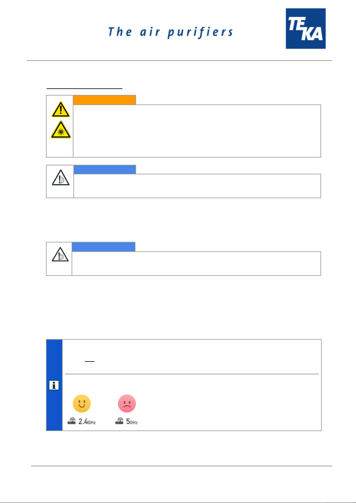
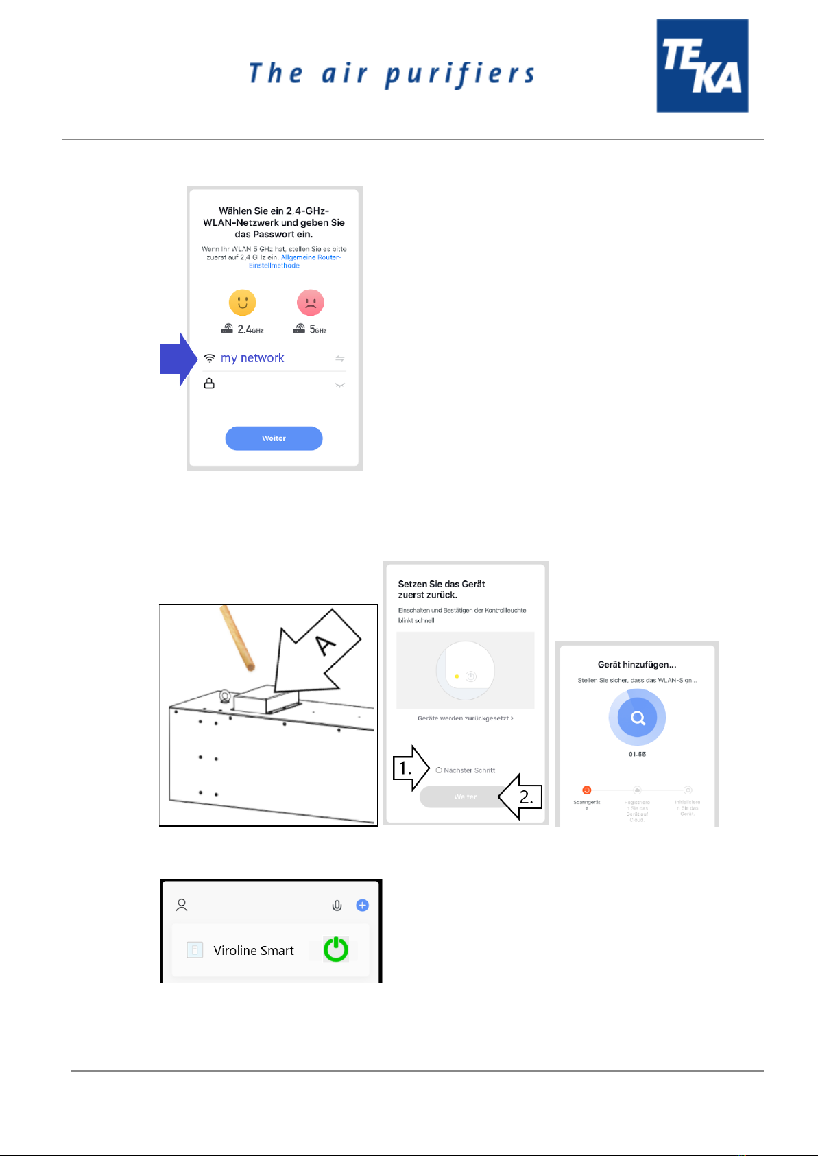
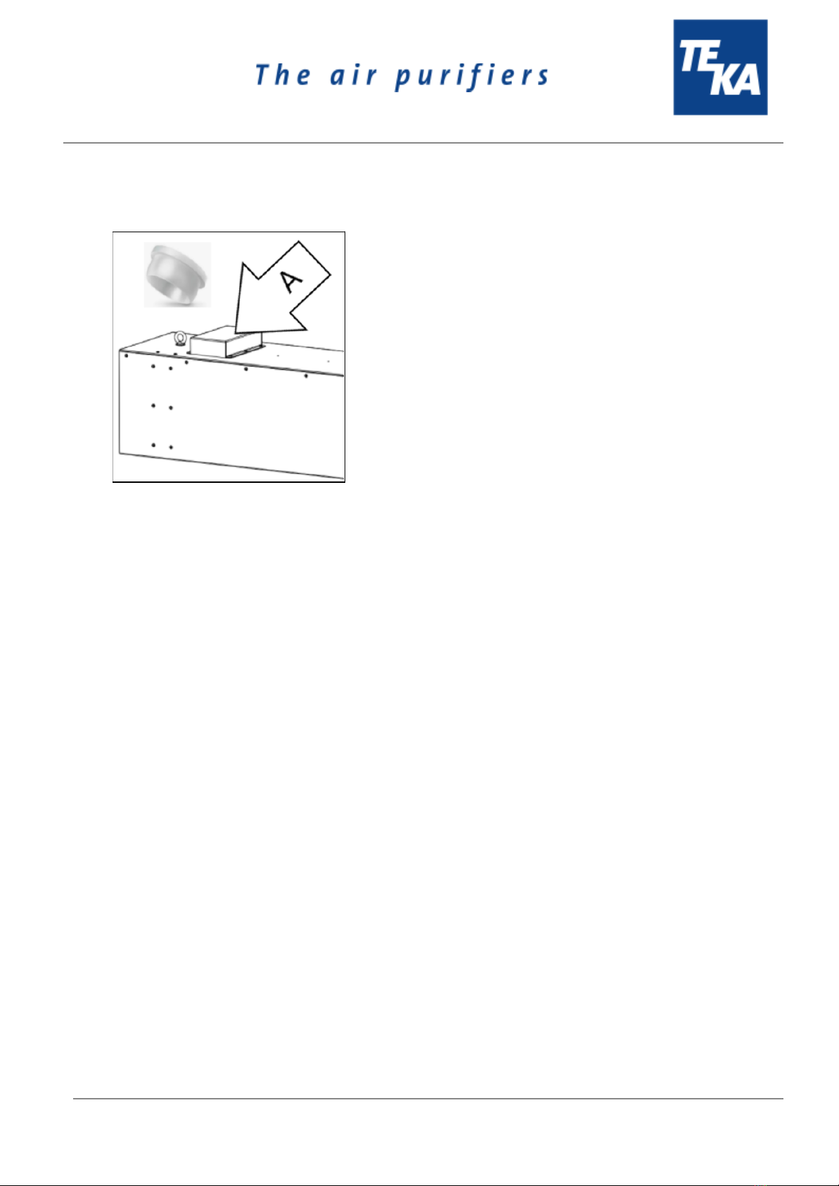
The “WiFi” version of the device first has to be commissioned before being installed below
the ceiling, see chapter “Commissioning”.
NOTICE
Damage or functional impairment of the unit due to climatic influences.
The unit must be stored in a dry place and protected against moisture during transport. As a
matter of principle, the filter unit is not designed to be installed outside.
BA_VIROLINE-SMART_200921_EN
6
12.01.2022

5. Commissioning
WARNING
Dangers arising from a defective condition of the unit. There is also a risk to the eyes
if there is a direct view of the UV-C lamp.
Make sure that the measures described in this chapter are completed before the
commissioning of the unit. All required connections must be attached before turning the unit
on. Do not operate the unit if any components are defective, missing or damaged. Check the
orderly condition of the unit before switching it on. The unit must not be operated without a
filter element.
NOTICE
Damaged supply lines.
Make sure that the supply lines are protected against damage by forklift trucks and similar
events. Protect all supply lines from heat, moisture, oil and sharp edges.
5.1. Electrical connection
NOTICE
Electric malfunction possible in cause of an incorrect power supply.
Pay attention to the admissible supply voltage. Please observe the specifications on the type
plate.
● Connect the mains cable (see chapter 2.1) to the power supply.
5.2. Integration in the WLAN and app (“WiFi” version)
This section only applies
● to the “WiFi” device version, not the “Basic” version,
● and if the device version “WiFi” can be switched on and off via the app. This then
requires the device to be integrated into the WLAN network and into the app.
Integration in the WLAN is only possible if the network is set to 2.4 GHz. Otherwise the WLAN
must be set to 2.4 GHz, for example in the router settings.
BA_VIROLINE-SMART_200921_EN
7
12.01.2022

Procecure:
● To control the “VIROLINE SMART WiFi”, choose a terminal device that is already integrated in
the existing WLAN. Alternatively, add the required terminal device to the WLAN.
● Download the required app “Smart Life - Smart Living”onto your terminal device:
Android:
https://play.google.com/store/apps/details?id=com.tuya.smartlife&hl=de
Apple:
https://apps.apple.com/de/app/smart-life-smart-living/id1115101477
● Start the App.
● Create a new account (A), or attempt to perform the operation without creating an account (B).
● Add a new device. Next, choose to change WLAN (WiFi).
BA_VIROLINE-SMART_200921_EN
8
12.01.2022

● Select your WLAN.
You now see a prompt telling you to reset the device. To do this, press the button (C) on the
inside built receiver. Actuate this using the wooden stick supplied through the opening "A", so
that the control lamp of the inside built receiver starts to flash quickly. As soon as the lamp
starts to glow permanently, you must tick “Next Step” on the terminal device (1.) and press
“Next” (2.).
● As soon as the device has been recognised, this is indicated on the terminal device.
● The device can then be attached to the intended location.
BA_VIROLINE-SMART_200921_EN
9
12.01.2022

5.3. Attach the plug
The supplied plug Ø6 mm must be attached to the opening “A” if not already done.
BA_VIROLINE-SMART_200921_EN
10
12.01.2022

6. Operating the system
6.1. Explanation of the operating elements
Operating elements for the device control
Representa
tion
Designation
Description / function
Version “Basic”:
ON-OFF-switch
By means of this switch, the device is switched on and off.
When the device is switched off, it is not disconnected from
the power supply.
If the system does not switch on, check whether this is because a
timer is being used.
+
Version “WiFi”:
ON-OFF-switch
+
App
By means of this switch, the device is switched on and off.
Alternatively, the system can also be started using the app (see
chapter “Commissioning”):
When the device is switched off, it is not disconnected from
the power supply.
If the system does not switch on, check whether this is because a
timer is being used.
When disconnected from the power supply, the system
remembers the last operating state. When power is supplied
again, the system may switch on directly.
Timer
A timer is enclosed and may optionally be used. However, the system
can also be used without this.
BA_VIROLINE-SMART_200921_EN
11
12.01.2022

7. Maintenance
In accordance with national regulations, the operator is obliged to carry out repeat and functional tests.
Unless otherwise specified by national regulations, we recommend regular visual inspections and
functional tests of the device as described in the chapter “Maintenance intervals”.
You find the chapter “Maintenance intervals” at the end of the document. The general
maintenance (visual inspection, etc.) is also explained there.
In the chapter “Maintenance intervals” there is information on the maintenance intervals of the filter
elements. But these are only recommendations. Depending on the application (multi-shift operation,
dust generation, ...) it may be necessary for the operator to change the maintenance intervals.
In this chapter the maintenance work which is caused by wear caused during operation is described.
WARNING
Work on the open system entails the risk of electrical shock or accidental restart the
system. Both pose a danger to life and limb. There is also a risk to the eyes if there is
a direct view of the UV-C lamp.
When cleaning and servicing equipment during the replacement of parts or when changing
to another function, set the device to maintenance condition first (see chapter “Reset to
maintenance state”).
A recommissioning of the device must only occur if it is ensured that the device is
functionally equivalent to the original state.
CAUTION
Hazards to the respiratory tracts are possible.
All maintenance work must only be carried out in well-ventilated rooms and
while wearing an appropriate respiratory mask! We recommend: respiratory
protection half mask DIN EN 141/143 protection level P3. For all maintenance
work ensure a cautious handling of filter elements and components in order to
avoid whirling up dust.
Notes regarding SARS-CoV-2 (Coronavirus)
In relation with SARS-CoV-2, the german RKI (Robert-Koch-Institut) has
published a section on its website with information on the disposal of waste::
https://www.rki.de/DE/Content/InfAZ/N/Neuartiges_Coronavirus/Hygiene.html
Please note that the information provided there (e.g. on waste disposal) is
updated from time to time. So always take into account the current status of
waste disposal.
We recommend: Stow the changed (filter) elements in tear-resistant and tightly
closed plastic bags before disposal, so that contact is avoided in the further
disposal process. Disposal can take place via the mixed waste / residual waste.
The operator is obliged to store and dispose of the collected dust in accordance with national or
regional regulations. For all maintenance or cleaning work please refer to the applying
environmental regulations. Pollutants and filter elements must be disposed of or stored according
to the regulations as well. If you have any doubts, we recommend contacting a disposal
contractor in your area.
BA_VIROLINE-SMART_200921_EN
12
12.01.2022

7.1. Reset to maintenance state
● Switch off the unit. Unplug the mains plug. Secure the unit against unauthorized restarting
during maintenance.
● After completion of all maintenance work the unit can be reconnected to the power supply.
7.2. Replacing the microfilter mats
The microfilter mats must be changed after a certain number of operating hours. The time depends on
the amount of accumulated dust, and therefore cannot be determined beforehand.
CAUTION
Whirling up dust is possible.
The microfilter mat is a disposable filter element. Do not try to clean the filter element.
● Release the protective grilles on both sides (suction grille and exhaust grille, see chapter 2.1).
To do this, release the 4 screw connections of both grilles.
● Replace the microfilter mats with new ones.
Only use TEKA spare filters. Otherwise the proper functioning of the unit is
not guaranteed.
● Screw on the protective grilles again.
BA_VIROLINE-SMART_200921_EN
13
12.01.2022

7.3. Recplacing the UV-C lamp
CAUTION
Risk of burns when touching the UV-C lamp.
After switching off the system, wait 5 minutes before changing.
NOTICE
Reduction of the UV-C light transmission is possible.
Grease residues can burn into the glass elements. Do not touch the glass
elements with your fingers. Use gloves.
● Release the exhaust grille (see chapter 2.1). To do this, release the 4 screw connections.
Remove the microfilter mat.
● There is another protective grille behind the microfilter mat. Also release this.
● Now carefully pull the UV-C lamp out from its holder.
● Insert the new UV-C lamp.
Only use TEKA spare parts. Otherwise the proper functioning of the unit is
not guaranteed.
● Mount the inner protective grille, the microfilter mat and the exhaust grille again.
BA_VIROLINE-SMART_200921_EN
14
12.01.2022

8. Dismantling / Disposal
Only authorised personnel may disassemble the machine.
WARNING
Dangers arising from electricity.
Before the dismantling of the machine it has to be disconnected from the power supply and
all supply lines.
CAUTION
Whirling up dust is possible due to the deposited dust.
During all work a suitable respiratory protection and protective clothing have to
be worn.
The operator is obliged to store and dispose of the collected dust in accordance with national or
regional regulations.
9. Diagnostics and troubleshooting
A list of possible system errors is provided in the table.
A recommissioning of the device must only occur if it is ensured that the system is functionally
equivalent to the original state. Repairs may only be carried out by TEKA personnel or, after
consultation with TEKA GmbH, by the personnel authorised by the operator.
Adhere to the instructions in the chapter "Safety instructions" and " Maintenance" when carrying out any
repairs. If in doubt, contact our TEKA service department:
Tel: +49 2541-84841-0
E-mail: [email protected]
Fault
Cause
Removal
System does not start.
Plug power supply is missing or
incorrectly inserted.
Plug connector check power
supply / plug in correctly.
Further informations see chapter
“Operating the system”.
No power at outlet.
Check the mains, remove error if
possible.
Suction power too low
Filter element is saturated.
Replace the filter package,
dispose of old filter properly!
Suction line contracted.
Check and fix.
Exhaust line contracted.
Check and fix.
BA_VIROLINE-SMART_200921_EN
15
12.01.2022

10. List of spare parts
Filter element
Article no.
Microfilter mats (2 pieces):
for version “SMART Basic”
for version “SMART WiFi”
100311
100312
Other parts
Article no.
UV-C lamp
100310
11. Technical data
Version
VIROLINE SMART Basic
VIROLINE SMART WiFi
Supply voltage
V
230
230
Frequency
Hz
50
50
Type of current
Ph
1
1
Engine power
kW
0,027
0,038
Air flow volume max.
m³/h
400
700
Protection class
IP54
IP54
ISO class
F
F
Width
Depth
Height
mm
mm
mm
1000
290
290
1000
345
345
Weight
kg
16
19,5
Sound pressure level
dB(A)
43
43
Allowed ambient temperature
°C
+5 to +35 (during operations)
-10 to +40 (during transport and storage)
Allowed max. humidity
%
70
BA_VIROLINE-SMART_200921_EN
16
12.01.2022

12. EC declaration of conformity
according to the Machinery Directive 2006/42/EG, Annex II, 1 A
TEKA Absaug- und Entsorgungstechnologie GmbH
Millenkamp 9, D-48653 Coesfeld
Designation of the device: VIROLINE SMART
We hereby declare under our sole responsibility that the product mentioned above, from the serial
number A18200010011001 resp. P39000010011001 on, conforms to the following directives:
Machinery Directive: 2006/42/EG
Electromagnetic Compatibility: 2014/30/EU
This declaration will become void if the device is exposed to modifications that are not approved by the
manufacturer in written form.
Authorized representative for the technical documentation:
TEKA Absaug- und Entsorgungstechnologie GmbH, Millenkamp 9, D-48653 Coesfeld
(Jürgen Kemper, managing director)
Coesfeld, 3rd july 2020
BA_VIROLINE-SMART_200921_EN
17
12.01.2022

13. Training protocol
Designation of the device: VIROLINE SMART
(This form can be used by the operator to document the training of the employees. Training should be performed by
authorized personnel only. Refer to the instructions in Chapter "Safety Instructions")
By his signature, the employee confirms that he has been instructed regarding the following items:
Instruction
completed
Description of the device
Operation and application of the device
Explanation of the safety instructions
Behavior in case of fire
Explanation of the operation elements
Change and dedusting of the filter elements
Appropriate disposal
Maintenance works / Maintenance intervals
Name of the employee (legible)
Signature
Introduction through (legible):
Signature:
BA_VIROLINE-SMART_200921_EN
18
12.01.2022

14. Maintenance intervals
14.1. Usage-related maintenance
The described maintenances become necessary through the demands of the system operations. The
maintenance intervals are recommendations. Depending on the application (multi-shift operation, dust
generation, ...) it may make sense for the operator to change the intervals of maintenance, replacing
and cleaning.
Maintenance work must always be documented by means of a protocol.
The approach of the maintenance measures is described in chapter "Maintenance".
Maintenance work
Chapter
Maintenance interval
recommended by TEKA
determined by the operator
Replacing the microfilter mats
(or check the degree of pollution)
7.2
semi-annually
Replacing the UV-C lamp
7.3
after 9000 operation hours (this is absolutely necessary as the
lamps lose intensity over time)
14.2. General maintenance
The described maintenances are independent from the demands of the system operations.
The operator is obliged to carry out repeated inspections and functional tests according to national
regulations. If not otherwise covered by national regulations, the described maintenance intervals must
be respected.
Maintenance work must always be documented by means of a protocol.
Maintenance work
Chapter
Maintenance interval
Visual inspection of the device
14.2.1
weekly
Functional test of the device
14.2.2
monthly
Electrical test of the electrical lines and earthing connections
14.2.3
annually
BA_VIROLINE-SMART_200921_EN
19
12.01.2022

14.2.1. Visual inspection of the device
Visual inspection: Observation that there are no visible safety-related defects.
WARNING
Danger arising from the ready to operate condition of the device.
Follow the procedure as described in the chapter “Set to maintenance state”.
The following steps must be carried out in the course of the visual inspection:
● Ensure that all parts are firmly connected.
● Check all metal parts for corrosion or damages / changes of the coating.
● Visual inspection of the control and operating elements as well as the outside running cables for
damages.
14.2.2. Functional test of the device
NOTICE
Possible material damage due to faulty condition of the unit.
Carry out a visual inspection before the functional test of the device as described in the
previous chapters.
The work as described in the chapter “Commissioning” must be finished.
The following steps must be carried out in the course of the functional test:
● Switch on the device.
● Pay attention to extraneous noises or vibrations during the device´s operation.
● Check if the collection of the ambient air is sufficient. (Visual inspection).
14.2.3. Electrical test of the electrical lines and earthing connections
WARNING
Danger arising from electricity.
The operator is responsible for ensuring that all work on electric components is carried out
by authorised and qualified personnel.
The device is subject to regular electrical checks by the operator of the device, and are subject to
national standards of the different countries.
The here recommended maintenance interval complies with the in Germany applying "Regulation 3 of
the German Social Accident Insurance - Electrical plants and equipment" (formerly known as BGV-A3).
The check must only be carried out by a qualified electrician or a person trained in electrics using
suitable measuring and test devices. The scope of testing and the methods must be in line with the
respective national standard. All contacts in the control cabinet must be checked for tight fit, and must
be readjusted if necessary.
BA_VIROLINE-SMART_200921_EN
20
12.01.2022
This manual suits for next models
4
Table of contents
Other Teka Ventilation Hood manuals

Teka
Teka DHI Series User manual

Teka
Teka TGF3 270 EU User manual

Teka
Teka TL1-62 User manual

Teka
Teka DG2-ISLA User manual

Teka
Teka RBF 78650 SS User manual

Teka
Teka DVT 68660 TBS User manual

Teka
Teka GFL 651 EOS User manual

Teka
Teka DU User manual

Teka
Teka CNL 6415 PLUS User manual

Teka
Teka DBV-60 User manual