manuals.online logo
Brands
  1. Home
  2. •
  3. Brands
  4. •
  5. Tektronix
  6. •
  7. Measuring Instrument
  8. •
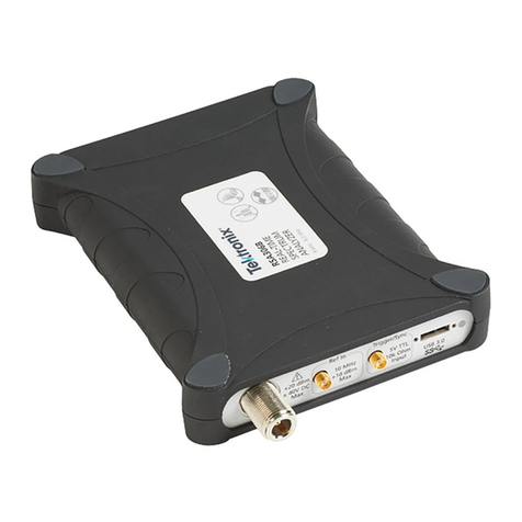
  9. Tektronix TPR1000 Installation instructions

Tektronix TPR1000 Installation instructions

Terms in this manual
These termsmay appear in thismanual:
WARNING. Warning statements identifyconditions or
practices that could result in injury or loss of life.
CAUTION. Caution statements identify conditions or
practicesthatcould result in damage to this product or
other property.
Symbolsand terms on the product
When this symbol is marked on the product, be
sure to consult the manual to find out the nature of
the potential hazards and any actions which have
to be taken to avoidthem. (Thissymbol may also
be used to refer the user to ratings in the manual.)
The followingsymbol(s) may appear on theproduct:
Compliance information
Thisproduct is intended for use by professionalsand trained
personnelonly; it is notdesigned for use in households or by
children.
Questionsabout the following compliance information may be
directed to the following address:
Tektronix,Inc.
PO Box 500, MS 19-045
Beaverton, OR 97077,USA
www.tek.com
Environmental considerations
Thissection provides information aboutthe environmental
impact of the product.
Restriction of hazardous substances
Complies withRoHS2 Directive2011/65/EU.
Product end-of-lifehandling
Observe the followingguidelines when recycling an instrument
or component:
Equipment recycling.Production of this equipment required
the extraction and use of natural resources. The equipment may
contain substancesthatcould be harmful to the environment or
humanhealthifimproperly handledat the product’s end of life.
To avoid release of such substancesinto the environment and
to reduce the use of naturalresources, we encourageyou to
recycle thisproduct in an appropriatesystem thatwill ensure
thatmost of the materials are reused or recycled appropriately.
Thissymbol indicates that this product complies
with the applicable European Union requirements
according to Directives 2012/19/EU and
2006/66/EC on waste electricaland electronic
equipment(WEEE) and batteries. For information
about recycling options, check the Tektronix Web
site (www.tek.com/productrecycling).
Operating overview
The TPR1000and TPR4000probesprovide a low noise, large
offset range solution for measurement of ripple on DC power
rails ranging from–60to+60 VDC and measurement of AC
ripple between 200μVp-pand1Vp-pat up to4GHz.
Refer to one of the followingTPR1000and TPR4000
Instruction Manuals for complete operating information and
product specifications. The manualsare available for download
at www.tek.com\downloads.
Language Tektronix partnumber
English 077-1542-xx
Japanese 077-1543-xx
Simplified
Chinese
077-1544-xx
Environmental specifications
SpecificationDescription
Maximum input
voltage
DC: ±60 V
AC: ±30 V RMS
Pk-Pk: ±42 V peak
Temperature Probe body: 0 to +55 °C
Standard accessories: –40to+125 °C
High-temp accessories: –55 to +155 °C
Humidity 5 to 95% up to +40 °C, derate to 85% above
+40 °C
Altitude 0 to 3000 m
1
2
3
4
Key performance specifications
Specification Description
Oscilloscope
compatibility
6 series MSO, 5 series MSO,
MSO/DPO3000, MDO/DPO4000,
MSO/DPO5000, DPO7000, and
DPO70000 1oscilloscopes
Bandwidth in DC
coupling mode 2 3
TPR1000: DC to1GHz
TPR4000: DC to4GHz
Bandwidth in DC
reject mode2 3
TPR1000: 10 kHz to1GHz
TPR4000: 10 kHz to4GHz
Linear dynamic
range
Up to 60 V DC, ±1 Vp-p to bandwidth 4
Offset range ±60 V
Attenuation 1.25x 2
Measurement
accuracy
DC linearity: <0.1%
Step response long-term aberrations: ±1%
Noise<300 μVp-p noise on6Series MSO (20 MHz
BW Limit)
<1 mVp-p noise on 6 Series MSO (Full
Bandwidth)
Input impedance50 kΩDC to 10 kHz
50 ΩAC > 100 kHz
Offset ±60 V offset range
Offset setting error: ±2 mV max, ±0.4 μV
typical
DPO70000 oscilloscopes require the optionalTCA-VPI50adapter.
Frequency response optimized for <1 Ωsource impedance.
Through SMA-to-SMA cable or Solder Micro-Coax tip.
Max AC RMS of 1 V.
Standard accessories
Eachprobe is shipped with oneTPR4KIT accessory kit
containing the following items:
noitpircseDmetI
1.3 m cable, SMA male-to-MMCX
male, 50 Ω
1.3 m cable, SMA male-to-SMA male,
50 Ω
Y-lead adapter, MMCX
female-to-0.8 mm sockets
Adapter cable, MMCX female-to-U.FL
female, 50 Ω
Adapter, MMCX female-to-square pin
(0.062 centers)
DUT interface solder pins, set of 20
Soldering aide tool, 0.062 solder pins
over SMT
Solder-in cable adapter, MMCX
female-to-solder micro-coax tip, 50 Ω,
set of 3
Solder-in cable adapter, MMCX
female-to-solderflex-paddle tip, 50Ω,
set of 3
Wire card, solderable enameled
self-fluxing copper wire (for use with
the solder-in tips)
Probe tip tripodsupport (withliving
hinge)
Marker bands, set of 5 (for probe
identification)
xx
Important Safety information
Thismanual contains information and warningsthatmust be
followedbytheuser for safeoperation andtokeep the product
in a safe condition.
To safelyperform service on this product,additional
information is provided at the end of this section in the Service
safetysummary.
General safety summary
Use the product only as specified. Review the following safety
precautions to avoid injury and preventdamage to thisproduct
or anyproductsconnected to it. Carefullyreadall instructions.
Retain these instructionsfor future reference.
Probes and testleads
Before connectingprobes or test leads, connectthepower cord
from the powerconnector to a properlygroundedpower outlet.
Inspect the probe and accessories. Before each use, inspect
probeandaccessoriesfor damage (cuts, tears, or defects in
the probebody, accessories, or cable jacket). Do not use if
damaged.
Hightemperatureprobetips
WARNING.To preventaburn injury, whenusingasolder
micro-coax or flex tip in a hightemperature application, be
sure to allow the tip to cooldownbefore handling the tip.
Servicesafety summary
TheService safety summary section contains additional
information required to safelyperformservice on the product.
Only qualified personnel should performservice procedures.
ReadthisService safety summary and theGeneral safety
summary beforeperforming any service procedures.
Do not service alone. Do notperforminternalservice or
adjustments of thisproductunless anotherperson capable of
rendering first aid and resuscitation is present.
TPR1000and TPR4000
Active Power Rail Probes
Compliance andSafety Instructions
x
1
*P071363700*
071-3637-00
1. To install the probe, slide theprobebodyinto the
FlexChannel or VPI receptacle. The probeclicks into
place when fully engaged.
2. Attachone of the followingprobecables to the SMA
connector on theprobebody:
SMA-to-SMA standardcable (standardaccessory)
SMA-to-MMCX standardcable(standardaccessory)
SMA-to-MMCX high-temperature cable(optional
accessory)
1GHzbrowserprobecable (optional accessory)
CAUTION. To preventdamage to the probe, do not exceed
8 in-lbs torque on the SMAnut.
3. To disconnect the probe, press the latch release button and
pull away from the instrument.
Attaching MMCX accessories
Gently insert the MMCX end of the cableintoone of the
followingaccessories: micro-coaxtip, solderflex tip, u.fl
adapter or MMCX to squarepin Y-lead adapter, until you feel
the connector engage. To remove an accessory, gently pull
from the MMCXconnectionpoint.
Attaching solder-in accessories
Micro-coax tip.For convenientfirst-time use, the solder
micro-coax tips are shippedpre-trimmed and ready to be
soldered to the testpoint. You canreuse a tip by removing the
tip fromthe solder joint and then trimming the wire insulation
backtoexpose the center pin and ground shield on the tip cable.
To achieve the best measurements results with a trimmed tip,
refer to the TPR1000andTPR4000UserManualforguidelines
and a description of best practices.
Flex tip. To attach the solderflex tip,first solder the enameled
self-fluxingcopper wire (standardaccessory) to the testpoint.
Feedthe wire through the vias on the end of the flextip, and
thenapply a small amount of solder to the vias to attachthe
wire to thetip.
Using the solder-pin installation tool
The supplied set of solderpinsare intended to be installed
on DUTcircuitboards and usedwiththe supplied
MMCX-to-square-pinadapter. To install the solder pins,use
the supplied soldering-aide tool as describedbelow .
NOTE.The solder pins are extremely small andcan be
challenging to handle. It is recommended to use tweezers and a
magnifying tool when installingpins on a circuit board.
1. Carefully insertthe solderpins into the soldering aide tool
as shown below.
2. Use the soldering aide tool to hold the solder pins in place
while soldering the pins to the circuitboard.
3. If necessary, apply a small amount of adhesive to further
strengthen the connection to the circuit board. However,
keeptheheight of the adhesive to a minimum to provide
goodelectricalcontact for the adapter.
Optional high-temperatureaccessorykit
If youordered the optional TPR4KITHT high-temperature
accessorykit,youreceivedthe following items:
noitpircseDmetI
2 m high-temperature cable, SMA
male-to-MMCX male, 50 Ω
Solder-in cable adapter, MMCX
female-to-solder micro-coax tip, 50 Ω,
set of 3
Solder-in cable adapter, MMCX
female-to-solderflex-paddle tip, 50Ω,
set of 3
Optional 1 GHz browseraccessory kit
If youordered the optional TPRBRWSR1G browser accessory
kit, youreceivedthe following items:
noitpircseDmetI
Browser
Ground leads (blade, 0.5 mm spring,
15 cm alligator)
Y-lead adapter, browser tip-to-0.8 mm
sockets
Micro-SMD clip
Replacement 0.5 mm browser tips
(2 solid tips, 2 spring tips)
Optional solder-in, micro-coax tip accessory kit
If youordered the optional TPR4SIACOAX accessorykit,you
received the following items:
noitpircseDmetI
Solder-in cable adapter, MMCX
female-to-solder micro-coax tip, 50 Ω,
set of 3
Optional solder-in, flex-paddle tip accessory kit
If youordered the optional TPR4SIAFLEXaccessorykit, you
received the following items:
noitpircseDmetI
Solder-in cable adapter, MMCX
female-to-solderflex-paddle tip, 50Ω,
set of 3
Installation
NOTE. Your FlexChannel or VPI instrumentmay require a
software upgrade to support full functionality of the TPR1000
andTPR4000 probes. Before you connectthe probe to an
oscilloscope, refer to the required software versionstable at the
endof this document to checkthe version requirements.
Copyright © Tektronix, Inc. All rights reserved.
Usingtheoptional1GHzbrowser
Theoptional 1 GHzbrowserkitcontains the following parts:
1 GHz browserprobe, square pin Y-leadadapter, micro-SMD
clip, threegroundleads (alligator, blade, spring), and four
replacement probe-tippins (two rigid, two spring loaded).
WARNING.To prevent injury to the operator or damage
to the probe,oscilloscope and deviceunder test, do not
touch the probe groundtoanypoint that is not at the same
potential as the chassis ground of theoscilloscope. The
probe ground must be connected to the samepotential as
the chassis ground of the oscilloscope.
Installing ground leads. To obtain accurate measurements,
alwaysattach a ground lead to the probe tip beforemaking
measurements. It is recommended thatyou use the shortest
groundleadthatwillfunction in your electrical application.The
following illustration showsthebrowserprobe tip, the tip cover
and the three types of grounds leads supplied with the browser.
To install the ground leads:
Spring: Slide the groundleadover the probetipuntil it
seats aroundthe metalportion of the probe-tiphousing.
Alligator: Slide the ground leadprongsover the exposed
metal between the plasticprobe-tipsections.
Blade:Locatethe slot in the probe-tiphousing as shown
below. Slide the groundleadovertheprobetipuntil the
blade slides into the slot.
Connecting the Y-lead adapter and micro-SMD clip. The browser
kit includes a Y-leadadapter and a micro-SMD clip thatconnect
as shownbelow. The Y-leadadapter can alsoconnecttosquare
pins.
Replacing browser-tip pins. To removethebrowser-tip pin,use
pliers to grasp the pin and gently pullitout of thetiphousing.
To install a new browser-tip pin, select between a solid (silver
colored)orspring-loaded(gold colored)pin, and thenuse pliers
to gently insertthepininto the browser-tiphousinguntil you
feel the pin press against the bottom of the housing.
Required oscilloscope software versions
OscilloscopeRequired software version 1
5 and 6 Series MSO 1.12.5
MSO/DPO3000 1.27462
MDO/DPO4000 1.09354
MDO/DPO5000 10.8.3.3
DPO7000 10.8.3.3
DPO70000 10.9.1
1Theprobemayoperate with olderversions of oscilloscopesoftware. However,
older softwareversionsthan thoselisted arenotguaranteedtoprovide full
probefunctionality.
www.tek.com
Other manuals for TPR1000

1

This manual suits for next models

1

Other Tektronix Measuring Instrument manuals

Tektronix WVR8300 User manual

Tektronix

Tektronix WVR8300 User manual

Tektronix RSA3408B User manual

Tektronix

Tektronix RSA3408B User manual

Tektronix 8001A User manual

Tektronix

Tektronix 8001A User manual

Tektronix TekRanger 2 TFS3031 User manual

Tektronix

Tektronix TekRanger 2 TFS3031 User manual

Tektronix P5102 User manual

Tektronix

Tektronix P5102 User manual

Tektronix P5200 User manual

Tektronix

Tektronix P5200 User manual

Tektronix VM5000 Series Owner's manual

Tektronix

Tektronix VM5000 Series Owner's manual

Tektronix Type 130 User manual

Tektronix

Tektronix Type 130 User manual

Tektronix IsoVu TIVP02 User manual

Tektronix

Tektronix IsoVu TIVP02 User manual

Tektronix TLA7AA1 User manual

Tektronix

Tektronix TLA7AA1 User manual

Tektronix AM503S User manual

Tektronix

Tektronix AM503S User manual

Tektronix 495 User manual

Tektronix

Tektronix 495 User manual

Tektronix TLA6402 Installation and maintenance instructions

Tektronix

Tektronix TLA6402 Installation and maintenance instructions

Tektronix VM700T Operating and maintenance manual

Tektronix

Tektronix VM700T Operating and maintenance manual

Tektronix IsoVu TIVP Series User manual

Tektronix

Tektronix IsoVu TIVP Series User manual

Tektronix TPA-N-VPI User manual

Tektronix

Tektronix TPA-N-VPI User manual

Tektronix P7350 User manual

Tektronix

Tektronix P7350 User manual

Tektronix P6248 User manual

Tektronix

Tektronix P6248 User manual

Tektronix 7D01 User manual

Tektronix

Tektronix 7D01 User manual

Tektronix MTS4000 MPEG User manual

Tektronix

Tektronix MTS4000 MPEG User manual

Tektronix RSA5103 User manual

Tektronix

Tektronix RSA5103 User manual

Tektronix 492P Operating and maintenance manual

Tektronix

Tektronix 492P Operating and maintenance manual

Tektronix P2100 User manual

Tektronix

Tektronix P2100 User manual

Tektronix KEITHLEY 2450-EC User manual

Tektronix

Tektronix KEITHLEY 2450-EC User manual

Popular Measuring Instrument manuals by other brands

Keysight Technologies U5309A Startup guide

Keysight Technologies

Keysight Technologies U5309A Startup guide

Norav Medical NR-1207-3 Installation and operation guide

Norav Medical

Norav Medical NR-1207-3 Installation and operation guide

ABB LWT300 series quick start guide

ABB

ABB LWT300 series quick start guide

3M Clean-Trace quick start guide

3M

3M Clean-Trace quick start guide

Rigel MULTI-FLO instruction manual

Rigel

Rigel MULTI-FLO instruction manual

Purkay Labs AUDIT-BUDDY Gen 2 user manual

Purkay Labs

Purkay Labs AUDIT-BUDDY Gen 2 user manual

BRUEL & KJAER 2825 Service manual

BRUEL & KJAER

BRUEL & KJAER 2825 Service manual

REED R2800 instruction manual

REED

REED R2800 instruction manual

MILANDR MILUR 107 Operation manual

MILANDR

MILANDR MILUR 107 Operation manual

DOLD BH 5922 Safety Technique

DOLD

DOLD BH 5922 Safety Technique

Starrett 436.1 user manual

Starrett

Starrett 436.1 user manual

Ultraflux Minisonic_600-2 user manual

Ultraflux

Ultraflux Minisonic_600-2 user manual

Onicon SYSTEM-20 Installation and operation guide

Onicon

Onicon SYSTEM-20 Installation and operation guide

PCB Piezotronics 3741B122G Installation and operating manual

PCB Piezotronics

PCB Piezotronics 3741B122G Installation and operating manual

Axiometrix Solutions imc BUSDAQflex Getting started

Axiometrix Solutions

Axiometrix Solutions imc BUSDAQflex Getting started

AKCP ILPM manual

AKCP

AKCP ILPM manual

Vixen Horns VXA7240C installation guide

Vixen Horns

Vixen Horns VXA7240C installation guide

Rion NA-27 instruction manual

Rion

Rion NA-27 instruction manual

manuals.online logo
manuals.online logoBrands
  • About & Mission
  • Contact us
  • Privacy Policy
  • Terms and Conditions

Copyright 2025 Manuals.Online. All Rights Reserved.