Genaral
Information
Section
1-7S14
CHARACTERISTICS
The
Tektmnlx7S14 Dual
Trace
May&
Sweep
Sampler
is
a
general
purpuse
samplingunit with
a
DE-1
000
MHz
bandwidth.
It will
operate
In
any
Tektrmlx
7000
Senes
mainframe.
Tha
front paneltem~nologyis similar to
that
of
convent~nalmc~llosoopes.
The
7514 has
two time
bases
to
provide "delaying" and
"delaved
sweep"
'ation.
The
ddaved
sweep
starts after
mints
is
the
productof the reading
on
the
Delay
Kme
Mult
dial
times
the
DelayingSweep
WDiv
ming.
Delay
lines inthe inputsignel channels permitdisplay
of
the leading
edge
of
the trigering waveform.
The
Auto
Level meprovides
a
bright baseline
in
the
absence
of
a
triggering signal. Other featurer indude 2mVldiv
sensitiviw, low tangential noise, versatiletr~ggetingmpabil-
itiss,
a
broad
range
of
sweep
rate, and
crt
readout
of
both
the
attenuation
and
timing values.
the
sttlected
delay lyntenral, givingthe effect
of
a
wide-range
sweep
operation.
The
delayed sweep
starts
after the The characterirtics
given
in
the
followingTableapplwover
selected delw interval, giving the
etfecf
of
a
wide-range an ambient temperature
range
from
O'C
to
+W*C
after
€he
sweep magn~fier.
The
calibrated
delay
replam the "time imtrurnem
has
been
=librated
at
+25'~
t5'~.
Under
these
pos~tion"
control
fountl
on
most
sampling time-baseunits. conditions, the
7S14
will
pwform
to
therequirementsgiven
in
the Performance
Check
section
of
this
manual.
The
JS14
has
a
two
dot
time-interval mmsuremem
method
that
prowdep
a means
of
measuring
the
time The Supplemental
information
column
of
the
Table
been
two
mints
on
the
"normal" (delaying)d~splav.
A
provides additional information
about
the operation
of
the
brightened
dot
on
the trace
can
be
m~t~onedto the
start
7514.
Characteristiu given in the Supplemental Infor-
of
the event to
be
measured.
A second brlghtend
dot
an
mation column
are
not
requirementsinzhernselves
and
are
be
pdsit~oned
to
the
end
of
the
event
bv
using the Delay not necessarily
checked
rn
the Performance Check
Time
Mult control.
The
time interval between the
two
~rocedure.
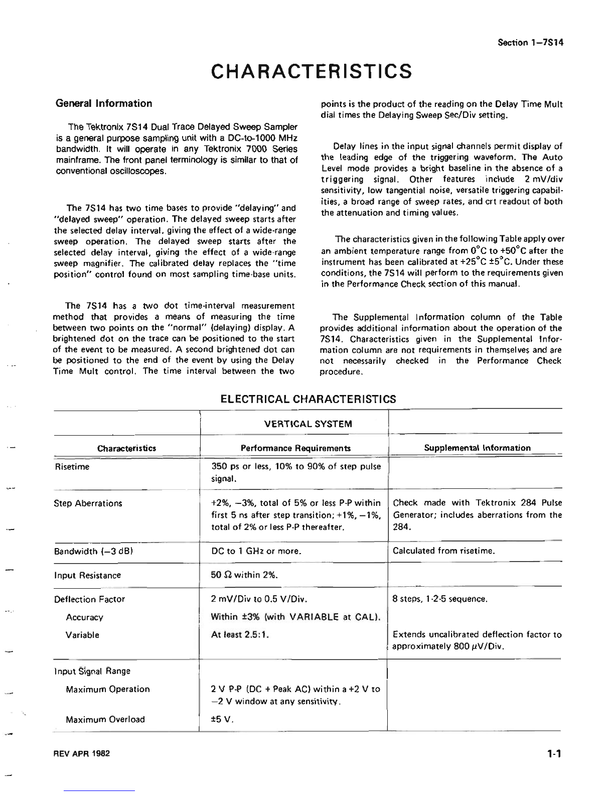
ELECTRICAL
CHARACTERI!XICS
VERTICAL
SYSTEM
I
I
350
ps
or Iesa,
10%
to
90%
of step pulse
]
I1
Step Aberrations
+2%,
-3%.
total
of
5%
or
Teps
P-P
within made with Tektronix
284
Pulse
first
5
m
after
step transition;+l%.
-3%.
includes aberntiom from the
totat of
2%
or
less
P-P
thereafrer.
Bandwidth
(-3
dB)
I
DC
to
1
GHr
or
more.
(
Calculmedfrom risetime.
Accuracy
I
Within
23%
(with
VARIABLE
at
CAP].
I
Input
Reistance
DeflectionFactor
50
within
2%.
I
2
mVlDiv to
0.5
VIDiv.
8
stew,
4-2-5
sequence.
MaximumOperation
2
V
P-P
(DC
+Peak
AC]
within a
+2
V
to
-2
V
window
at
any
sensitivity.
Variable
Input
Signal
Range
At least 251. Extends
urnlibrated
deflection
factor
to
I
approximately
800
pV/Div.
Maximum
Overload
*5
V.