Hyperlinked Page
.
Scroll UP or Down
.
Left click to select
2336
Service
Figure
LIST OF ILLUSTRATIONS
Page
...
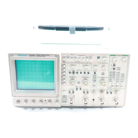
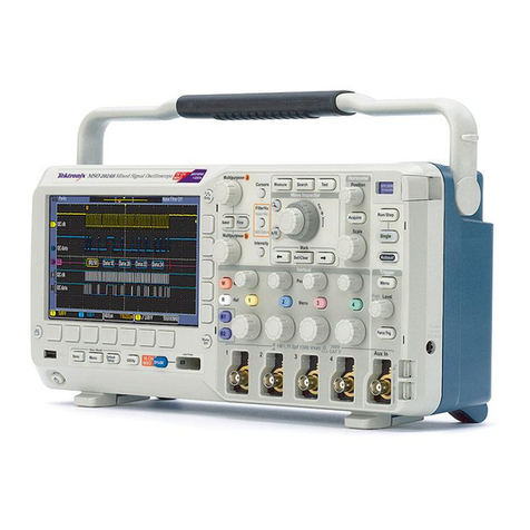
The 2336 Oscilloscope
VIII
LINE VOLTAGE SELECTOR switch. line fuse. and power cord
...................
2-2
................................................
Optional power cords 2-2
..................................
Power and display controls and indicators 2-3
..................
Vertical controls. connectors. and indicatorsand calibrator output 2-4
........................................
Horizontal controls and indicator 2-5
..............................
A
TRIGGER controls. connector. and indicator 2-6
............................B TRIGGER controls. connector. and LCD readout 2-8
...............................................
Rear-panelconnectors 2-9
........................................
Graticule measurement markings 2-9
................................
Basic block diagram of the 2336 Oscilloscope 3-3
Channel
1
Vertical Attenuator. simplified block diagram
.........................
3-6
Vertical Preamplifier. Diode Gate. and Delay Line Driver. simplified block diagram
.......
3-8
...................................
Diode Gate biasing for Channel 1display 3-9
....................
Simplified illustration of Multiplexer U215 switching operation 3-11
...................................
Trigger circuitry. detailed block diagram 3-14
...................................
Trigger signal slow path (lowfrequency) 3-15
...................................
Trigger signal fast path (high frequency) 3-16
Simplified diagram of the
B
Trigger Generator and
B
Source and
B
Slope
..................................................
switching circuitry 3-18
....................................
Sweep operation in the
A
Sweep Mode 3-23
.....................................
Sweep circuit waveform relationships 3-24
....................................
Sweep operation in the B Sweep Mode 3-25
................................
Horizontal Amplifier. detailed block diagram
3-27
...............................
High-Voltage Oscillator wavefrom relationships 3-29
....................................
DC Restorer circuit. simplified diagram 3-33
...............................................
Foldover circuit action 3-34
....................
Typical waveforms in the Fan Motor three-stage inverter circuit 3-35
Simplified diagram of the Delay Time Switching and Prescaling circuit
...............
3-38
.......................................
Exclusive-ORgate switching action 3-41
...............................
Test setup for external trigger and jitter checks 4-15
......................
Areas affected by high-frequency compensation adjustments 5-15
.........................................
Multipin connector orientation 6-7
.......................................
Attenuator contact pressure check 6-11
..........................................
Attenuator contact alignment 6-11
.........................................
SECIDIV switch exploded view 6-24
.......................................
Vertical attenuator exploded view 6-28
Hyperlinked Page
.
Scroll UP or Down
.
Left click to select
iii

