442 Service
LIST OF ILLUSTRATIONS
Fig-
No. Page
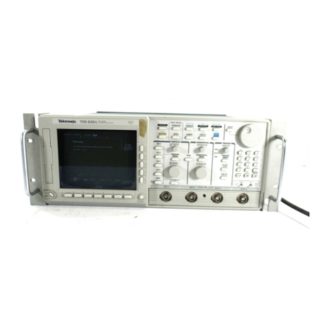
442 Oscilloscope
.......................................
viii
1- 1 442 Oscilloscope dimensions.................... 1-6
2- 1 Commonly used power plugs ................. 2-2
2-2 Power swi ch loca ions on bo om of he
442 ............................................................ 2-2
2-3 Power inpu fuse loca ion on he 442 back
panel.......................................................... 2-3
2-4 Cr Display and Power fron panel con rols
and connec ors
.......................................
2-3
2-5 Ex ernal Z AXIS INPUT connec or on he
back panel of he 442
..............................
2-4
2-6 Con rols and swi ches accessible hrough
he bo om of he 442 cabine
................
2-5
2-7 Ver ical sys em con rols.......................... 2-5
2-8 Horizon al sys em con rols
.....................
2-6
2-9 Triggering sys em con rols
.....................
2-7
2-10 Probe Compensa ion .
.
...........................
2-9
2-11 Display of 0.5 V PROBE ADJ ou pu signal 2-10
2-12 Measuring peak- o-peak vol age of a
waveform................................................... 2-11
2-13 Measuring ins an aneous dc vol age wi h
respec o a reference vol age
................
2-11
2-14 Measuring he ime dura ion be ween
poin s on a waveform
..............................
2-14
2-15 Measuring rise im e
.................................
2-15
2-16 Measuring ime difference be ween wo
pulses
.......................................................
2-15
2-17 Measuring phase difference...................... 2-16
2- 18 Phase difference measuremen wi h an X-Y
display ..................................................... 2-17
3- 1 Sweep genera or and sweep ga e iming
diagram..................................................... 3-9
3- 2 Foldback circui ac ion
.............................
3-10
4- 1 Ver ical deflec ion accuracy es se up . . 4-5
4-2 Bandwid h check es se up
......................
4-7
4-3 Triggering and Z-Axis inpu .check es
se up
.........................................................
4-9
4-4 Timing accuracy check es se up
..........
4-11
4-5 442 cabine removal
.................................
4-13
4-6 Moving In erface board o adjus men
access posi ion
.......................................
4-15
4-7 Low-vol age power supply adjus men
loca ion..................................................... 4-17
Fig.
No. Page
4-8 In erface board adjus men loca ions
(board shown in access posi ion)
...........
4-18
4-9 Ver ical a enua or, preamplifier, delay line
driver, and CH 2 dc rigger level adjus men
loca ions................................................... 4-21
4-10 Display of correc (idealized) a enua or
compensa ion .......................................... 4-21
4-11 Horizon al adjus men loca ions on A14
Horizon al Ou pu board.......................... 4-23
4-12 Horizon al adjus men loca ions on A12
Horizon al board and A ll Trigger Swi ch
board
.......................................................
4-24
4- 13 Triggering and X-Axis adjus men loca ions
on he A11 Trigger Swi ch board............ 4-26
5- 1 Cabine removal
........................................
5-1
5-2 Moving In erface board o access posi ion 5-3
5-3 Color codes............................................... 5-5
5-4 Semiconduc or lead configura ion
..........
5-6
5-5 Mul i-pin connec or holder indexing .... 5-7
5-6 Pin connec or re-ins alla ion in mul i-pin
holders
.....................................................
5-15
5-7 Shaf -knob assembly removal
.................
5-17
5-8 A enua ors, A enua or Shif , Horizon al
Ou pu , and Power Supply assembly
removal..................................................... 5-17
5-9 In erface, Trigger Swi ch, Horizon al, and
Timing (SEC/DIV swi ch) assemblies
removal..................................................... 5-19
The following illustrations are located on foldout
pages in Section 7 Diagrams and Circuit Board
Illustrations.
7-1 A6—CH 1 A enua or circui board
componen loca ions
7-2 A7—CH 2 A enua or circui board
componen loca ions
7-3 A enua or circui board loca ions
7-4 442 Oscilloscope block diagram
7-5 A8—Ver ical circui board componen
loca ions
7-6 Ver ical circui board loca ion
ii REV A MAY 1980
