Operating
In
struct
io
n
s-7
8
52
To install the
7852
into a plug-in compartment, push it
in
until it fits firmly i
nto
the compartment.
To
remove, pull
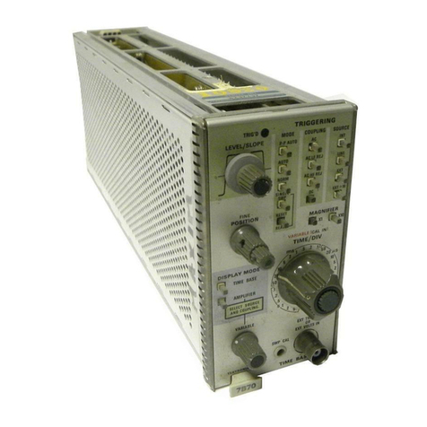
the release latch (see Fig. 2·2) to disengage
the
unit from
the indicator oscilloscope and pull it
out
of the plug-in
compartment. Even though the horizontal gain
of
the
inc:li-
cator
oscilloscope
is
standardized to minimize adjustment
when inserting plug·ins. the sweep calibration
of
the
7852
should be checked. The procedure for checki
ng
the unit
is
given under Sweep Calibration Check
in
the First-Time
Operating Instructions
of
this section.
REl.EASE
l.ATCH
.,"
TWIll.
,.-
~~
DUAL TIME BASE
Fig.
2·2.
L
oe.
t
io
n of
re
le
s$fI
l
atc
h.
FRONT·
PANEl
C
ONTROLS
and CONNECTORS
General
All
controls required for the operation of
the
7652
are
located on the front panel
of
the unit (see Fig. 2·3) with
the
exception of the internal DELAYED TRIGGER
SOURCE and
MA
IN
-FRAME
DE
L
AY
I
NG
MODE
sw
itches.
To make full use
of
the capabilities
of
this instrument, the
operator should be familiar with the function and use
of
each
of
these controls. A detailed description
of
the front·
panel controls and connectors
is
given here.
Main Triggering Controls
LEVEL/SLOPE
2·2
The LEVEL/SLOPE control deter-
mines whether the trigger
ci
rcuit
responds on the positive-going
or
negative-going portion
of
the trigger
signal. When the indicator line on
the
outer
ring of the
lEVEL!
SLOPE control
is
to the left
of
center, the display starts on the
positive-going portion
of
the wave-
form (notice positiveijoing wave-
form symbol to l
eft
of
control). To
the right
of
center, the display
starts on the negativeijoing portion
TRIG'D
LAMP
of
the waveform (notice negative·
going
waveform symbol). When
several cycles
of
a signal appear
in
the display. the
se
lection of the
trigger slope
is
often unimportant.
However.
if
only a certain portion
of
a cycle
is
to be displayed, correct
setti
ng
of the LEVEL/SLOPE con·
trol
is
important to provide a dis·
play which starts on the desired
slope
of
the input signal.
The lEVELISLOPE control
deter
·
mines the voltage level on the trig.
ger signal
at
which the display
is
triggered,
as
well
as
selecting the
tr
igger
slope. The center knob
of
the LEVEL/SLOPE control pro·
vides about a 3:1 reduction
in
rela·
tion to the
outer
indicator ring, to
allow precise
level
selection. This
control can also be turned through-
out
the complete 3600 rotation to
allow continuous triggering over the
selected slope. When the
lEVEL!
SL
OPE
control
is
set to the line on
either the positive-going
or
nega-
t ive-going waveform symbol the
sweep
is
triggered near
the
zero-volt
Ievei of the trigger signal lAC
coupled only). As the LEVEL!
SLOPE control
is
rotated
;may
from the zero line, the displayed
waveform starts
at
a
point
carre·
sponding to the position
of
the
ind icator tine on the associated
slope
waveform
symbol.
For
example,
if
the LEVEL/SLOPE
control
is
turned clockwise from
the zero line
on
the positiveijoing
slope symbol. the displaved wave·
form starts
at
a more positive level.
Before
setting the triggering
level,
select the TRIGGERiNG
MODE, COUP
LI
NG
and SOURCE.
Then
adj
ust the lEVEL/SLOPE
control
SO
the displayed waveform
starts
at
the
desired point. The trig-
gering slope can be changed
at
any
time
by
rotating the LEVEL!
SLOPE
control
to the corre-
sponding point on the
other
sl
ope
waveform symbol.
The TRIG'D lamp provides a con-
venient indication of the condition
of
the trigger circuits.
If
the
MAIN
®
