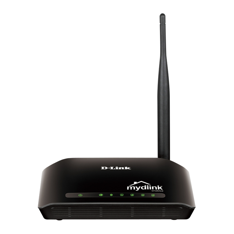
Teldat H2 RAIL User manual

Teldat H2 Automotive Router
Installation Manual
Copyright© Teldat Dm687-I Version 1.4 03/2020 Teldat S.A.
Teldat S.A. Manual
Teldat H2 Automotive Router 1

Legal Notice
Warranty
This publication is subject to change.
Teldat S.A. offers no warranty whatsoever for information contained in this manual.
Teldat S.A. is not liable for any direct, indirect, collateral, consequential or any other damage connected to the deliv-
ery, supply or use of this manual.
Manual Teldat S.A.
2Teldat H2 Automotive Router

Table of Contents
Chapter1 AboutthisGuide.................................. 1
1.1 Supporteddevices................................... 1
1.2 Who should read this manual? . . . . . . . . . . . . . . . . . . . . . . . . . . . . . . 1
1.3 When should I read this manual? . . . . . . . . . . . . . . . . . . . . . . . . . . . . . 1
1.4 Whatisinthismanual?................................. 1
1.5 Whatisnotinthismanual? ............................... 1
1.6 How is the information organized? . . . . . . . . . . . . . . . . . . . . . . . . . . . . 1
1.7 Technicalsupport.................................... 1
1.8 Relateddocumentation................................. 2
Chapter 2 Teldat H2 Automotive Router . . . . . . . . . . . . . . . . . . . . . . . . . . . 3
2.1 Features........................................ 3
2.1.1 Powersupply ..................................... 3
2.1.2 Hardwaremonitoring.................................. 3
Chapter 3 Components and Power Supply . . . . . . . . . . . . . . . . . . . . . . . . . . 4
3.1 Components...................................... 4
3.1.1 Frontpanel ...................................... 4
3.1.2 Rearpanel....................................... 5
3.2 Mountingoptions.................................... 7
3.2.1 Assembly: Recommendations . . . . . . . . . . . . . . . . . . . . . . . . . . . . . . 7
3.2.2 Outlinedrawing..................................... 8
3.3 Powersource ..................................... 8
3.3.1 Connecting the power cable to the vehicle . . . . . . . . . . . . . . . . . . . . . . . . . 8
3.3.2 Connecting the power cable to the device . . . . . . . . . . . . . . . . . . . . . . . . . 9
3.3.3 Cablefeatures.................................... 10
3.3.4 Configuring power management . . . . . . . . . . . . . . . . . . . . . . . . . . . . 10
3.3.5 Deactivating power management . . . . . . . . . . . . . . . . . . . . . . . . . . . . 10
3.3.6 Activating power management . . . . . . . . . . . . . . . . . . . . . . . . . . . . . 10
3.3.7 Deactivating On/Off switch . . . . . . . . . . . . . . . . . . . . . . . . . . . . . . . 11
3.4 Protectionfuse.................................... 12
3.5 RESETbutton.................................... 13
3.5.1 Rebootingthedevice................................. 13
3.5.2 Defaultconfiguration................................. 13
3.6 Connectingthedata.................................. 14
3.6.1 4-portEthernetswitch................................. 14
3.6.2 WANconnection................................... 14
Teldat S.A. Table of Contents
Teldat H2 Automotive Router i

3.6.3 Wireless LAN antenna connection (Wi-Fi connectors) . . . . . . . . . . . . . . . . . . . 15
3.6.4 Connecting a 3G USB device (USB connector) . . . . . . . . . . . . . . . . . . . . . . 15
3.6.5 Connecting for configuration . . . . . . . . . . . . . . . . . . . . . . . . . . . . . . 15
3.6.6 Connecting to a WWAN antenna (cell connectors) . . . . . . . . . . . . . . . . . . . . 16
3.6.7 Connecting the GPS antenna . . . . . . . . . . . . . . . . . . . . . . . . . . . . . 18
Chapter 4 Installing the SIM card . . . . . . . . . . . . . . . . . . . . . . . . . . . . . . 19
4.1 IdentifyingtheSIMtrays................................ 19
4.2 InstallingtheSIM................................... 20
Chapter 5 Teldat H2 Automotive module options . . . . . . . . . . . . . . . . . . . . . . 22
5.1 Interfaceassignment................................. 23
Chapter6 Compliance.................................... 25
6.1 Manufacturerinformation ............................... 25
6.2 Safetywarnings ................................... 28
6.3 WEEEinformation.................................. 28
6.4 REACH....................................... 29
6.5 EC declaration of conformity . . . . . . . . . . . . . . . . . . . . . . . . . . . . . . 29
6.6 CEmarking..................................... 29
6.7 Nationalrestrictions.................................. 30
6.8 Operatingfrequency ................................. 30
6.9 FCCstatement.................................... 30
6.9.1 Federal Communications Commission Interference . . . . . . . . . . . . . . . . . . . . 30
6.10 ICstatement..................................... 30
6.10.1 CANICES-3(A)/NMB(A) ............................... 30
Appendix A Technical Information. . . . . . . . . . . . . . . . . . . . . . . . . . . . . . . 31
A.1 Troubleshooting................................... 31
A.2 Updatingthesoftware................................. 31
A.3 Connectingtothedevice ............................... 31
A.3.1 Connecting through the local console (AUX connector) . . . . . . . . . . . . . . . . . . 31
A.3.2 Connecting through IP terminal (LAN 1...4 connectors) . . . . . . . . . . . . . . . . . . 32
A.4 Connectors ..................................... 33
A.4.1 LANconnector.................................... 33
A.4.2 WWANconnectors.................................. 33
A.4.3 WLANconnectors .................................. 33
A.4.4 GPSconnector.................................... 33
Table of Contents Teldat S.A.
ii Teldat H2 Automotive Router

A.4.5 AUXconnector.................................... 34
A.4.6 POWERsupplyconnector............................... 34
A.5 Technicalspecifications................................ 34
A.5.1 Architecturehardware................................. 34
A.5.2 LANinterface .................................... 35
A.5.3 WirelessWANinterface................................ 35
A.5.4 GPSinterface.................................... 35
A.5.5 WirelessLANinterface................................ 35
A.5.6 Configurationinterface ................................ 36
A.5.7 Powersupply .................................... 36
A.5.8 Dimensionsandweight................................ 36
A.5.9 Environmental specifications . . . . . . . . . . . . . . . . . . . . . . . . . . . . . . 37
AppendixB RadioInformation................................. 38
B.1 RFLTEspecifications................................. 38
B.2 RF GSM/WCDMA specifications . . . . . . . . . . . . . . . . . . . . . . . . . . . . 39
B.3 WIFIspecifications.................................. 40
Teldat S.A. Table of Contents
Teldat H2 Automotive Router iii

Chapter 1 About this Guide
Welcome to the Teldat H2 Automotive router family installation manual, which describes how to correctly install this
device in a working environment.
1.1 Supported devices
All the information contained herein applies to the Teldat H2 Automotive router family.
1.2 Who should read this manual?
This manual should be read by personnel who already have aftermarket installation experience and are familiar with
the general practices needed to install electronic devices in vehicles.
1.3 When should I read this manual?
This manual should be read when you wish to familiarize yourself with the device and its components.
This manual will give you a better understanding of your new device.
1.4 What is in this manual?
This installation guide contains information on:
• The features available on Teldat H2 Automotive routers.
• Technical specifications.
• Power supply requirements.
• The LEDs and connectors on the device.
• Troubleshooting.
1.5 What is not in this manual?
This manual does not contain any information relative to the software or configuration of the device. For configuration
instructions, please consult the relevant manuals for the different protocols, which can be found at the following web-
site:
http://www.teldat.com
1.6 How is the information organized?
Each chapter focuses on a specific part of the hardware and its components. All descriptions, technical specifications
and information on a component can be found in the relevant chapter.
1.7 Technical support
Teldat S.A. offers a technical support service. Regular software updates are available for maintenance purpose and
new features.
Contact information:
Web: http://www.teldat.com
Tel.: +34 918 076 565
Teldat S.A. 1 About this Guide
Teldat H2 Automotive Router 1

Fax: +34 918 076 566
Email: suppor[email protected]
1.8 Related documentation
Teldat Dm704-I Configuration Monitoring.
Teldat Dm748-I Software Updating.
Teldat Dm771-I Wireless LAN Interface.
Teldat Dm781-I Cellular Interface.
Teldat Dm812-I GPS.
Note
The manufacturer reserves the right to make changes and/or improvements to any and all parts of the
software and hardware of this product, and to modify the specifications of this manual without prior no-
tice.
The images showing the front and rear panels of the device are for information purposes only. The ac-
tual device may differ slightly from what is shown..
1 About this Guide Teldat S.A.
2Teldat H2 Automotive Router

Chapter 2 Teldat H2 Automotive Router
2.1 Features
2.1.1 Power supply
For further information about the different power supplies for the Teldat H2 Automotive router family, please refer to
the section headed Power source on page 8 in the chapter on Components and Power Supply on page 4.
2.1.2 Hardware monitoring
The Teldat H2 Automotive router hardware is monitored through the LEDs on the rear panel, which provide visual
information on what is happening in the device (status of hardware components, connection, data flow, etc.).
For further information on the LED panel, please see the section on Components on page 4 in the following chapter.
Teldat S.A. 2 Teldat H2 Automotive Router
Teldat H2 Automotive Router 3

Chapter 3 Components and Power Supply
The following chapter provides detailed information on the chassis of the Teldat H2 Automotive and its compon-
ents. This information includes:
• Components.
• Information on assembly.
• Power supply.
• RESET button.
• Data connection.
• SIM card installation.
3.1 Components
3.1.1 Front panel
The following figure shows the front panel.
Fig. 1: Front panel
The front panel components are as follows:
Front panel components
Item Description
A SIM Card. Slot where you can insert the SIM card for the secondary cellular mod-
ule.
B USB. Slot where you can insert an external USB modem.
C LAN 1..4. 4-port Gigabit Ethernet Switch.
D Eth WAN. WAN Gigabit Ethernet.
E On/Off switch.
F Rst. Reset button. For further information on how the reset button works, please
read the relevant chapter.
G WPS (Wireless Protected Setup). This allows for easy and secure configuration of
the Wi-Fi network parameters. For further information, please see the "Teldat-
Dm771-I Wireless LAN Interface" manual.
In addition to the connections, you can see a set of luminous indicators, or LEDs, on the front panel that provide in-
formation on what is happening in the router.
The Ethernet WAN port and the Switch LAN ports each have two LEDs (one yellow and one green) that reflect the
status of the connection according to the following table:
3 Components and Power Supply Teldat S.A.
4Teldat H2 Automotive Router

Switch and Ethernet WAN LED indicators
LED Associated Interface Description
Yellow LAN 1..4 and Eth WAN OFF -> Interface is unavailable, not installed or not re-
gistered.
ON -> Connected to 10 M:
- Steady: Is not transferring data.
- Blinking: Transferring data.
Yellow + Green LAN 1..4 and Eth WAN OFF -> Interface is unavailable, not installed or not re-
gistered.
ON -> Connected to 100 M:
- Steady: Is not transferring data.
- Blinking: Transferring data.
Green LAN 1..4 and Eth WAN OFF -> Interface is unavailable, not installed or not re-
gistered.
ON -> Connected to 1000 M:
- Steady: Is not transferring data.
- Blinking: Transferring data.
3.1.2 Rear panel
The following figure shows the rear panel.
Fig. 2: Rear panel
The rear panel components are as follows:
Rear panel components
Item Description
A Functional earthing. Usually not connected.
B 12-24 DC. Power source connection.
C LEDs:
• On: Illuminated indicator showing whether the device is switched on or not.
• A, B and C: explained in rear panel LEDs table.
D W1, W2. WiFi antennas for the Wireless LAN module. This module is optional
(your device may not have any antennas).
E C1, C2. Antennas for the Teldat H2 Automotive cellular module. This module is
Teldat S.A. 3 Components and Power Supply
Teldat H2 Automotive Router 5

optional (your device may not have any antennas).
F R1, R2, R3. Antennas for the Wireless LAN or cellular Main module.
G GPS. External GPS antenna.
H SIM card 2. Slot where you can insert a SIM card for the Main cellular module.
I AUX. DB9 connector that provides access to the device’s local console for config-
uration and monitoring.
In addition to the connections, you can see a set of luminous indicators, or LEDs, on the rear panel that provide in-
formation on what is happening in the router.
The LEDs on the rear panel of the router are shown in the following figure:
Fig. 3: Rear panel LEDs
Rear panel LEDs
LED Associated Interface Status Description
A Wireless WAN channel 0
(cellular1/1).
Monochrome green OFF -> Interface is unavail-
able, not installed or not re-
gistered.
ON -> Registering or re-
gistered and connected to
the SIM carrier network:
- Steady: Is not transferring
data.
- Blinking: Transferring
data.
B Wireless WAN channel 1
(cellular2/1).
Monochrome green OFF -> Interface is unavail-
able, not installed or not re-
gistered.
ON -> Registering or re-
gistered and connected to
the SIM carrier network:
- Steady: Is not transferring
data.
- Blinking: Transferring
data.
C The device has a MINI-PCI
slot where a Wireless LAN
daughter can be installed.
Monochrome green OFF -> Interface is unavail-
able, not installed or not es-
tablished.
ON -> Connecting or con-
nected and communications
3 Components and Power Supply Teldat S.A.
6Teldat H2 Automotive Router

established:
- Steady: Is not transferring
data.
- Blinking: Transferring
data.
3.2 Mounting options
The Teldat H2 Automotive device can be mounted in various vehicles on the wall, ceiling or on a horizontal surface.
The front and rear panels have two openings where you can add a bracket with slots to firmly hold the device in
place.
Fig. 4: Front panel bracket mounting
3.2.1 Assembly: Recommendations
We recommend that the device is mounted on a horizontal surface and that it is screwed to this surface using the
bracket slots.
For the mounting to be secure, we recommend using the following screws:
• For sheet metal installation, use #8 self-drilling screws.
• For tapped holes, use M4 machine screws.
Warning
If the screws are not properly anchored, the strain of the cables connected to the router could pull the
router out.
Note
The assembly screws are not provided with the router and must be purchased separately.
Teldat S.A. 3 Components and Power Supply
Teldat H2 Automotive Router 7

3.2.2 Outline drawing
An outline drawing is provided for proper installation.
Fig. 5: Outline drawing
3.3 Power source
The Teldat H2 Automotive router family is powered through direct current (DC).
Workplace Conditions. Main Characteristics
• Avoid humid and/or dusty locations.
• Avoid direct exposure to sunlight and any other heat sources. Do not place the device between papers, magazines
or other items that could hinder natural air circulation.
• Do not place the device near strong electromagnetic fields such as those produced by speakers, motors, etc.
• The device should not be placed too close to the driver or in areas where it might distract him/her.
• Avoid knocks and/or strong vibrations during operation, storage and transport.
• The device should be mounted in accordance with accepted aftermarket practices and materials.
Warning
The electric current in power cables, telephone lines and communication cables is dangerous. To pre-
vent electric shocks, before installing, handling or opening the equipment covers, connect and discon-
nect the cables following the steps set forth in Connecting on page 9 and Disconnecting on page 9.
3.3.1 Connecting the power cable to the vehicle
The device power supply cable must be connected to the vehicle’s fuse box. Always follow the recommendations of
the vehicle manufacturer on the connection of electrical accessories.
The following are some general tips:
3 Components and Power Supply Teldat S.A.
8Teldat H2 Automotive Router

• Disconnect the positive battery cable from the vehicle’s battery post.
• Find an empty fuse slot with 5 A - 10 A fuse ratings.
• Terminate the cable conductors with suitable crimp connectors, fuse tap or bare wires (depending on the fuse box
connectors).
• Connect the BATTERY conductor to the fuse connector.
• Connect the GND conductor to a battery ground connector.
• Alternatively, the IGNITION conductor can be connected to the vehicle's ignition switch (if available).
• We recommended installing an approved vehicle circuit breaker.
• Insert the new fuse into the fuse slot.
• Connect the positive battery cable to the vehicle’s battery post.
Fig. 6: Cable Connection to vehicle power source
All components used in the connection to the vehicle should be UL Listed and comply with the regulations of the
country where the installation takes place.
The cabling should be separated from other vehicle wiring and should be routed away from sharp edges.
The power supply cable goes from the fuse panel to the router along the vehicle wall (ALWAYS inside the vehicle
cabin and NOT crossing the vehicle’s firewall protection).
3.3.2 Connecting the power cable to the device
3.3.2.1 Connecting
• Make sure that the power supply cable is not connected to the device.
• Connect the data cables.
• Locate the 12 - 24 V DC connector, which is found on the rear part of the device.
• Insert the power cable connector.
3.3.2.2 Disconnecting
• Disconnect the power supply cable from the device.
• Disconnect the data cables.
3.3.2.3 Power connector pinout
PIN Signal
1 -
2 +
3 ACC / IGNITION
4 Functional Earth
Teldat S.A. 3 Components and Power Supply
Teldat H2 Automotive Router 9

3.3.3 Cable features
In the United States and Canada, the cable should be UL Listed, SAE type GPT Cable, min 18AWG.
Note
The cable features may depend on the recommendations of the country where the equipment is in-
stalled. The cable must always be 18 A WG or greater.
3.3.4 Configuring power management
The power management system of the Teldat H2 Automotive:
- stops the device from switching on until the vehicle has started.
- when installed, the device switches off a short time after the vehicle turns off. The purpose of this slight delay is to
keep the device from disconnecting during short stops.
This feature is configured using the internal micro-switches (SW1). However, the duration of the delay has to be set
using the configuration command.
The micro-switches are located in the device, as shown in following figure.
Fig. 7: Power management switch
3.3.5 Deactivating power management
Micro-switches SW1 2 and 3, labeled IGNITION, must be OFF.
3.3.6 Activating power management
Micro-switches SW1 2 and 3, labeled IGNITION, must be ON.
Caution
This is a factory setting i.e. the devices are already configured like this by default.
3 Components and Power Supply Teldat S.A.
10 Teldat H2 Automotive Router

In this operating mode, the device expects to be constantly powered and the ACC / IGNITION signal operates as a
switch. When power is applied to the device (BATTERY /VCC) the device remains switched off. It will only switch on
when the ignition pin (ACC / IGNITION) sends a signal (+12 V or +24 V).
Similarly, if the ignition signal deactivates once the device has switched on, the device remains switched on for the
period of time configured through the set ignition-off-powerdown-timer <value> command.
*
*p 4
Config>set ?
application-active Permits you to select the code used to boot the router
console Set console configuration
contact-person Assign a name or identification to the contact-person
data-link Type of data link for a WAN line
default-conf Restores the default configuration
file-cfg Configure a configuration file as active
ftp Permits you to access the FTP configuration menu
host-location Physical location of the router
hostname Assign a name to a device
ignition-off-powerdown-timer Configure the time to router power down after car
ignition off
inactivity-timer Configure the maximum inactivity time
login Configure login options
password Configure the device access password
pool Number of bytes assigned to each memory pool
schedule-restart Allows to configure router reset schedule
telnet Access the TELNET protocol configuration
web-probe Access the Web probe configuration
Config>set ignition-off-powerdown-timer ?
<1..1440> Power down timeout in minutes
disabled Disable ignition off power down timer
Config>set ignition-off-powerdown-timer 10
Config>
For further information on this command, please see manual Teldat- Dm704-I Configuration and Monitoring.
3.3.7 Deactivating On/Off switch
Deactivating the On/Off Switch from the Teldat H2 Automotive is possible.
When the On/Off Switch is enabled, the schema looks like the following figure, with the JP5 connector connected:
Teldat S.A. 3 Components and Power Supply
Teldat H2 Automotive Router 11

Fig. 8: On/Off Switch enabled
If you want to disable the On/Off Switch, then the JP4 connector is connected:
Fig. 9: On/Off Switch disabled
3.4 Protection fuse
The Teldat H2 Automotive router family has an internal protection fuse incorporated with the aim of preventing
damage to the device and the surrounding area.
The following image shows where the protection fuse is located (F1).
3 Components and Power Supply Teldat S.A.
12 Teldat H2 Automotive Router

Fig. 10: Protection Fuse
If the device is not operating, please check that the fuse is correctly installed and has not blown.
Warning
The fuse must have the characteristics indicated by Teldat S.A..
3.5 RESET button
The Teldat H2 Automotive has a button labeled RESET on the rear panel of the device. This button is physically
protected to stop it from being accidentally pressed.To activate it, please use a sharp pointed object.
The features of the reset button are described below.
3.5.1 Rebooting the device
If you press the RST button once the device is running normally, it will restart.
3.5.2 Default configuration
The RST button allows you to reboot the device to its factory default settings by following these steps:
• With the device switched off, press and hold down the RST button and switch on the router using the ON/OFF
switch (1).
• Stop pressing the RST button after 5 seconds.
The router's default configuration establishes the following IP address and mask:
• IP address: 192.168.1.1
Teldat S.A. 3 Components and Power Supply
Teldat H2 Automotive Router 13

• IP mask: 255.255.255.0
Note
Some devices leave the factory with customized settings. This personalization can mean that the de-
fault configuration is different from the one shown above.
3.6 Connecting the data
The Teldat H2 Automotive has the following data connections:
3.6.1 4-port Ethernet switch
The Teldat H2 Automotive incorporates a 4-port 10/100/1000 BaseT switch with automatic MDI/MDIX to connect to
a local area network (LAN).
Please pay careful attention to the labeling to avoid mistaking this switch for other types of ports.
Fig. 11: LAN switch ports (4)
Note
During booting and BIOS mode, only the LAN 1 connector is available.
Warning
The equipment is intended to be installed by Service Personnel and only handled by qualified person-
nel. If not, the device may be damaged and malfunction.
3.6.2 WAN connection
The Teldat H2 Automotive incorporates an Ethernet WAN 10/100/1000 BaseT port with automatic MDI/MDIX.
The WAN port is independent of the switch and is operated just like any other interface.
Please pay careful attention to the labeling to avoid mistaking this switch for other types of ports:
Fig. 12: WAN PORT
3 Components and Power Supply Teldat S.A.
14 Teldat H2 Automotive Router

Note
Only the LAN 1 connector is available during booting and in BIOS mode.
3.6.3 Wireless LAN antenna connection (Wi-Fi connectors)
The Teldat H2 Automotive router family has three connectors for RF antennas, used to improve the quality of the
signal received and transmitted by the Wireless LAN Module 2, R1, R2 and R3 (future use). If the router has two
Wireless LAN modules, the connectors for Module 0 are W1 and W2.
These modules are internal and can be activated through the purchase of the corresponding software license. To as-
semble and remove the antennas, simply screw/unscrew them into/from the connectors labeled W, on the router's
rear panel.
Fig. 13: Wi-Fi Antennas
Note
Antennas must not be directly connected to the Teldat H2 Automotive , but at least 50 cm away.
3.6.4 Connecting a 3G USB device (USB connector)
The Teldat H2 Automotive has a USB HOST 2.0 Type A connector interface, compatible with 3G USB modems.
The interface can be activated by purchasing the appropriate software license.
Fig. 14: 3G USB Connector
Note
To see the list of compatible external USB modems, please visit:
http://www.teldat.com.
3.6.5 Connecting for configuration
The Teldat H2 Automotive router has a DB9 female connector on the front panel labeled AUX. that can be used as
a router configuration port or as a V.24 asynchronous serial port (through a configuration command). The behavior or
functionality of this interface must be preconfigured. By default, this interface is configured as a configuration port.
Therefore, this section focuses on how to make the connector operate in asynchronous port mode.
This interface allows you to connect asynchronous serial devices that do not need hardware control signals, i.e. en-
Teldat S.A. 3 Components and Power Supply
Teldat H2 Automotive Router 15
Other manuals for H2 RAIL
2
Table of contents
Other Teldat Wireless Router manuals

Teldat
Teldat Regesta-PLC User manual
Teldat
Teldat H1+ User manual
Teldat
Teldat Connect-4GE User manual

Teldat
Teldat APR222ac User manual

Teldat
Teldat Connect-104V User manual

Teldat
Teldat REGESTA 1 Manual
Teldat
Teldat ATLAS 50 User manual
Teldat
Teldat 4Ge User manual
Teldat
Teldat Connect-KFPlus User manual
Teldat
Teldat ATLAS 152 User manual

