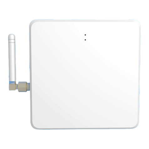
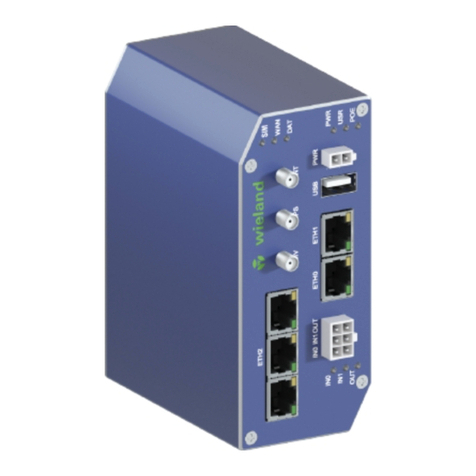
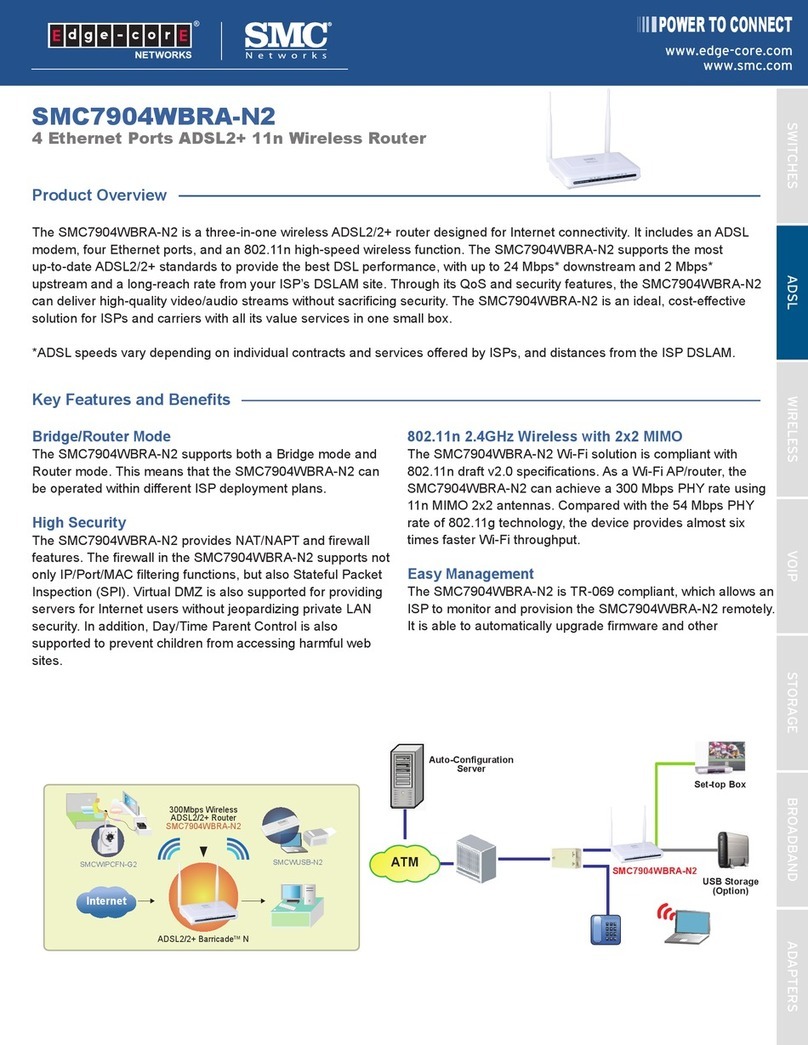
Teldat H1+ User manual

Teldat H1+/H1+GE
Installation Manual
Copyright© Teldat-DM449-I Version 6.1 7/2015 Teldat S.A.
Teldat S.A. Manual
Teldat H1+/H1+GE 1

Legal Notice
Warranty
This publication is subject to change.
Teldat S.A. offers no warranty whatsoever for information contained in this manual.
Teldat S.A. is not liable for any direct, indirect, collateral, consequential or any other damage connected to the deliv-
ery, supply or use of this manual.
Manual Teldat S.A.
2Teldat H1+/H1+GE

Table of Contents
I ImportantInformation................................ 1
Chapter1 InstallingtheRouter ................................ 2
1.1 Introduction...................................... 2
1.2 Connections...................................... 5
1.2.1 If the Ethernet cable isn’t POE . . . . . . . . . . . . . . . . . . . . . . . . . . . . . . 6
1.2.2 If the Ethernet cable is POE . . . . . . . . . . . . . . . . . . . . . . . . . . . . . . . 6
1.2.3 PowerSourceConnection................................ 7
1.2.4 DataConnections.................................... 8
1.2.5 Configuration Connection . . . . . . . . . . . . . . . . . . . . . . . . . . . . . . . 12
1.2.6 InstallingtheSIMcard................................. 14
1.3 MeaningoftheLEDs................................. 18
1.4 RSTButton..................................... 19
1.4.1 Procedure to ignore the current configuration and to establish the default configuration . . . . 19
1.4.2 Procedure to force start up in BOOT mode . . . . . . . . . . . . . . . . . . . . . . . . 21
1.4.3 Procedure to force start up in BIOS mode . . . . . . . . . . . . . . . . . . . . . . . . 23
1.5 Wallmounting.................................... 25
Appendix A Technical Information. . . . . . . . . . . . . . . . . . . . . . . . . . . . . . . 27
A.1 Troubleshooting................................... 27
A.2 SoftwareUpgrading.................................. 27
A.3 Connectors ..................................... 28
A.3.1 LANconnector.................................... 28
A.3.2 WANconnector ................................... 28
A.3.3 WWAN connectors (female) . . . . . . . . . . . . . . . . . . . . . . . . . . . . . . 28
A.3.4 WLANconnectors(male)............................... 29
A.3.5 USBconnector.................................... 29
A.3.6 FXS connector (optional) . . . . . . . . . . . . . . . . . . . . . . . . . . . . . . . 29
A.3.7 Configurationconnector................................ 29
A.3.8 Powerconnector................................... 30
A.4 TechnicalSpecifications................................ 30
Appendix B Regulatory compliance and safety information . . . . . . . . . . . . . . . . . 33
B.1 Recycling and the Environment . . . . . . . . . . . . . . . . . . . . . . . . . . . . . 33
B.2 Translated Safety Warnings . . . . . . . . . . . . . . . . . . . . . . . . . . . . . . 35
B.3 ComplianceInformation................................ 35
B.3.1 Compliance Information for Teldat H1+/H1+GE Routers Relevant to de European Union and Other
Countries Following the EU Directive 1999/5/EC (R&TTE Directive) . . . . . . . . . . . . . 35
Teldat S.A. Table of Contents
Teldat H1+/H1+GE i

Table of Contents Teldat S.A.
ii Teldat H1+/H1+GE

I Important Information
Caution
The manufacturer reserves the right to make changes and improvements to the appropriate features in
both the software and hardware of this product, modifying the specifications of this manual without prior
notice.
The images presented on the front and back panels of the devices are provided as information
guideline only. Some small modifications may exist in the actual device.
Warning
The equipment is intended to be installed by Service Personnel and only handled by qualified person-
nel. If not, the device may be damaged and malfunction.
This device contains elements that are sensitive to electrostatic surges and shocks. Therefore, it is es-
sential when handling the equipment that an antistatic wriststrap is connected to the device chassis and
that this is placed on an antistatic mat. Furthermore, it is crucial to avoid any kind of contact between
the device components and necklaces, bracelets, rings, ties etc.
Teldat S.A. Important Information
Teldat H1+/H1+GE 1

Chapter 1 Installing the Router
1.1 Introduction
The Teldat H1+ and Teldat H1+GE belong to the Teldat compact routers family. These routers have been especially
designed for remote SME and corporate enterprises that require IP connectivity through 3G and Ethernet access re-
spectively.
The Teldat H1+ and Teldat H1+GE routers are suitable for a wide variety of IP scenarios: from providing simultan-
eous access to Internet for private local area network users, to adapting to teleprocess networks and SNA support.
Their most common applications are:
• 3G access router
• Metroethernet access router
• Metroethernet access router with 3G backup
The Teldat H1+GE routers are designed to connect offices through a WAN Ethernet and consequently have a dedic-
ated gigabit Ethernet interface for WAN access. The Teldat H1+ routers are designed for 3G connectivity, integrating
a radio interface.
Both routers share the same motherboard and housing; consequently most of the installation procedures are the
same. The main difference between the Teldat H1+ and the Teldat H1+GE is that the latter doesn’t have a 3G integ-
rated interface (internal module).
With regard to the local area networks (LAN), the Teldat H1+GE has a four port Fast Ethernet Switch, while the
Teldat H1+ has a 5 port switch, 4 of these being Fast Ethernet and one a Gigabit Ethernet port.
The 3G connectivity is one of the key points of these devices, which can be used as a backup or the main link. In ad-
dition to the 3G integrated interface in the Teldat H1+, both devices support 3GUSB modems, which require a soft-
ware license. In both cases the modular design guarantees scalability as these routers can easily adapt to the latest
technologies that are emerging in this field. Consequently both devices are compatible with technologies such as:
GPRS, EDGE, UMTS, HSDPA, HSUPA, CDMA 2000 1xRTT, CDMA Ev-Do, etc.
In scenarios where network connectivity is critical for productive continuity, the Teldat H1+, router is the best option.
All that is required is a software license so that the Gigabit Ethernet port can be used to access the WAN network
(this is separated from the rest of the integrated Fast Ethernet switch ports), while maintaining the high performance
3G integrated interface as redundancy access. In cases where you have a Teldat H1+GE device, it’s also possible to
give response to this scenario through an external 3G-USB modem and the corresponding license so this interface
can be used in the device.
1 Installing the Router Teldat S.A.
2Teldat H1+/H1+GE

Fig. 1: 3G access router
Fig. 2: Metroethernet access router
Teldat S.A. 1 Installing the Router
Teldat H1+/H1+GE 3

Fig. 3: Metroethernet access router with 3G backup
Both devices also support Wireless LAN 802.11 b/g/n, and so only require a software license.
There are two Teldat H1+ and Teldat H1+GE router models:
(1) One model with an FXS connector so you can connect an analog telephone:
Fig. 4: Rear panel with FXS connector
Fig. 5: Front panel with an FXS LED
(2) Model without FXS connector:
1 Installing the Router Teldat S.A.
4Teldat H1+/H1+GE

Fig. 6: Rear panel without FXS connector
Fig. 7: Front panel without an FXS LED (AUX is there instead)
This manual shows you how to install and connect these devices.
Fig. 8: Teldat H1+/H1+GE: External aspect
1.2 Connections
Caution
Before connecting the router, please read the following instructions carefully.
Workplace Conditions. Main Characteristics
• Excessive cold and heat should be avoided, as should humidity and dust.
Teldat S.A. 1 Installing the Router
Teldat H1+/H1+GE 5

• Direct exposure to sunlight should be avoided as well as other heat sources. The device should not be placed
amongst papers, magazines or other elements that could hinder natural air circulation.
• The device should not be placed very close to strong electromagnetic fields such as speakers, engines, etc.
• Knocks and/or strong vibrations should be avoided during transport, operation and storage.
Warning
The electric current in power cables, telephone lines and communication cables is dangerous. To pre-
vent electric shocks, before installing, handling or opening the equipment covers, connect and discon-
nect the cables as follows:
1.2.1 If the Ethernet cable isn’t POE
To Connect To Disconnect
Make sure that the device power switch is in the OFF po-
sition (0)
Place the device power switch in the OFF position (0)
Check that the power supply is not connected to either
the main electricity supply or the device
Disconnect the power supply from the main electricity
supply
Connect all data cables Disconnect the power supply from the device
Connect the power supply to the device Disconnect the data cables
Connect the power supply to the main electricity supply
Place the device power switch in the ON position (1)
1.2.2 If the Ethernet cable is POE
To Connect To Disconnect
"
# $ !
# #%
# &$
# &$ $ # #
'& ()
'& ()
$ # #
%
" *
Note
Power supply through the POE Ethernet cable is independent from the device license.
1 Installing the Router Teldat S.A.
6Teldat H1+/H1+GE

1.2.3 Power Source Connection
The Teldat H1+/H1+GE router is either powered via an external AC/DC source or through the Ethernet cable (as
long as the latter complies with the POE 802.3af norm).
1.2.3.1 With an external power supply
Fig. 9: Connecting to the power supply using an external source
In order to connect the power supply to the device, please follow the aforementioned steps under section If the Ether-
net cable isn’t POE on page 6.
To avoid electric shocks, residual current circulation and other unwanted effects, also affecting communications, the
following is recommended:
Warning
All interconnected communication devices should be plugged to THE SAME GROUNDED POWER
OUTLET, which should at the same time be of good quality (lower than 10ohms).
Whether the workplace is provided with an uninterrupted power supply system (UPS), regulated supply
or it is independent from the rest (such as lighting, etc.); it is highly recommended that all data devices
should be connected to the same power source. This will avoid operating and premature aging prob-
lems of drivers and other components.
1.2.3.2 With POE injector
The Teldat H1+/H1+GE router can be powered through the Ethernet cable (as long as it complies with the POE
802.3af norm).
Teldat S.A. 1 Installing the Router
Teldat H1+/H1+GE 7

Fig. 10: POE Injector: Aspect
In order to connect the Ethernet cable, with POE power, to the device, please follow the aforementioned steps under
section If the Ethernet cable is POE on page 6.
The following schema details how to connect the POE injector to the device.
Fig. 11: Connecting to the power supply using the POE injector
1.2.4 Data Connections
The Teldat H1+/H1+GE router has the following connectors available:
1.2.4.1 4 port Ethernet Switch (connectors LAN1..4)
The Teldat H1+/H1+GE router has a 4 port 410/100BaseT switch incorporated with an automatic MDI/MDIX to con-
nect to the local area network (LAN).
1 Installing the Router Teldat S.A.
8Teldat H1+/H1+GE

Please pay close attention to the labeling. This is important in order to avoid confusing the switch with other types of
ports.
Fig. 12: LAN switch ports (4)
Note
During startup and in BIOS mode, only the LAN1 connector is available.
1.2.4.2 WAN Connection
The Teldat H1+/H1+GE router has a WAN Ethernet 10/100/1000BaseT port with an automatic MDI/MDIX.
In the Teldat H1+GE router, this port is independent of the Switch and is handled in the same way as another Ether-
net interface. In the Teldat H1+ router, this port forms part of the Switch when the WAN license hasn’t been activated
or behaves as Teldat H1+GE if the license has.
Please pay close attention to the labeling. This is important in order to avoid confusing the switch with other types of
ports.
Fig. 13: WAN port
Note
During startup and in BIOS mode, only the WAN connector isn’t operative.
1.2.4.3 Connecting the WWAN antenna
The Teldat H1+/H1+GE router has two connectors to connect the WWAN antennas. To assemble and dismantle the
antennas, simply screw them into the connectors labeled WWAN located at the rear of the device.
You must install the antennas in the Teldat H1+/H1+GE router in order to improve the quality of the signal received
and sent by the Wireless WAN module (GPRS, UMTS, HSDPA, HSUPA, etc.).
Teldat S.A. 1 Installing the Router
Teldat H1+/H1+GE 9

Note
Always install the WWAN antennas to achieve optimum performance from the router.
The device must have the corresponding software license installed in order to activate the Wireless
WAN interface.
Some cellular telephony technologies use antenna diversity techniques to improve the quality of the received signal
(HSUPA, CDMA EV-DO, etc.). For this reason, the Teldat H1+/H1+GE router incorporates two WWAN connectors,
labeled Main and Diversity.
Fig. 14: Wireless WAN antenna connectors
If the Main and Diversity antennas are not directly connected to the device but installed through extension cables, the
minimum distance between them must be 7cm and the maximum recommendable distance is 25 cm.
To achieve optimum performance from the installed radio frequency accessories (antennas and cables), these
should be the ones recommended by Teldat.
Teldat has a series of accessories (angled antennas, antennas for external use, ceiling antennas, extension cables,
etc.), which allow you to install the Teldat H1+/H1+GE in different locations.
Placing the antenna
The orientation of the antenna and its location with respect to other wireless devices and radiation devices (such as
communication devices, personal computers, etc.) can significantly influence the device performance.
The antennas transmit and receive radio signals. Performance is also affected by environmental factors such as the
distance between the device and the base station, physical obstacles and other interferences due to radio frequen-
cies (RF).
In order to achieve the best coverage, carry out the following instructions:
• Whenever possible, place the antenna where there are no physical obstacles. Obstacles between the Teldat-3Ge
and the base station degrade the RF signal. Place the device above ground level and ensure that it is suitably ori-
entated towards the nearest base station.
• Density of materials also affects the antennas. Place them away from any type of wall, metal screens, mirrors, etc.
• Do not place the antenna near columns that can produce shadow areas and reduce the coverage zone.
• Keep the antenna away from metal pipes such as canals, air-conditioning.
• Please bear in mind that other wireless devices (such as telephones, microwaves, etc.) can temporarily interfere
with the quality of the radio signal.
• We do not recommend that you install the antenna near or by racks containing communication devices, computers,
etc. Use an extension cable and place the antenna outside.
The following recommendations are applicable to all wireless devices:
• Do not touch or move the antenna while the device is transmitting or receiving.
1 Installing the Router Teldat S.A.
10 Teldat H1+/H1+GE

• When the antenna is transmitting, do not touch any equipment that contains devices that radiate very close to, or
touching, any exposed part of the body (particularly the face and eyes).
• Do not install the device in areas where the atmosphere is potentially explosive.
• Wireless devices can cause interferences with other devices. Do not use the device in areas where medical equip-
ment is installed.
• In order to ensure that you are complying with the R&TTE 1999/5/EC norm, the device must be at least 15 cm
away from a human body when it is operating.
1.2.4.4 Wireless LAN connection (ANT connectors)
The Teldat H1+/H1+GE router has two RF antenna connectors for an external antenna, in order to improve the qual-
ity of the signal received and transmitted by the Wireless LAN module. This module is internal and can be activated
by purchasing the corresponding software license. To assemble and dismantle the antennas provided with the
device, just screw them into the connectors, labeled ANT, which are located on the rear of the device.
Fig. 15: Wireless LAN antenna connectors
1.2.4.5 Connecting a 3G USB device (USB connector)
The Teldat H1+/H1+GE router has a USB HOST 2.0 Type A connector interface which allows 3G USB modems to
be connected. The interface can be activated by purchasing the corresponding software license.
Teldat S.A. 1 Installing the Router
Teldat H1+/H1+GE 11

Fig. 16: USB Connector
1.2.5 Configuration Connection
1.2.5.1 Configuring using the local console (CONF connector)
The Teldat H1+/H1+GE router has a female RJ45 connector on the rear panel labeled as “Conf.” which provides ac-
cess to the device’s local console. For configuration, you must connect the “Conf.” port to an asynchronous terminal
(or to a PC with terminal emulation).
Fig. 17: Configuration connector
Note
The configuration of the terminal must be:
- Speed: 9600 bps.
1 Installing the Router Teldat S.A.
12 Teldat H1+/H1+GE

- Eight data bits.
- One stop bit.
- No bit parity.
- No type of flow control.
Connection to the configuration port can be carried out with the RJ45 cable connectors provided with the device, to-
gether with a Female RJ45-Female DB9 adapter.
Note
The Female RJ45-Female DB9 adapter isn’t provided with the device, it is supplied separately.
Fig. 18: Connection for configuration
1.2.5.2 Configuring using an IP terminal (connectors LAN1..4)
The Teldat H1+/H1+GE router includes a default configuration that activates if the device has not been previous con-
figured or if the “Procedure to establish the default configuration” has been executed (this is explained further on in
this manual).
The router’s default configuration establishes the following IP address and the access mask:
• IP address: 192.168.1.1
• IP mask: 255.255.255.0
Teldat S.A. 1 Installing the Router
Teldat H1+/H1+GE 13

Note
Some devices leave the factory with a customized configuration for a specific client. This personaliza-
tion can mean that the default configuration is different from the one shown above.
This initial configuration allows you to access the device configuration console through the Telnet IP protocol. To do
this, carry out the following steps:
• Configure the IP terminal Ethernet interface (normally a PC) with IP address in the range of [192.168.1.2,
192.168.1.254] and mask 255.255.255.0. E.g. 192.168.1.2, 255.255.255.0.
• Connect the IP terminal Ethernet interface to any of the Teldat H1+/H1+GE router Ethernet Switch ports
(connectors LAN 1..4) through the Ethernet cable (RJ45) supplied with the device.
• Start a Telnet session from the IP terminal towards IP address 192.168.1.1 ( Teldat H1+/H1+GE router default ad-
dress).
• The default configuration does not request access credentials (user/password) to access the console.
For further information on how to fully configure the device, please see the manuals included on the CD supplied with
the Teldat H1+/H1+GE router.
1.2.6 Installing the SIM card
The Teldat H1+/H1+GE has a Wireless WAN interface, which means that at least one SIM card must be inserted in
the device so it is operative. There are certain services (CDMA) from some operators in several countries that do not
require SIM cards.
The Teldat H1+/H1+GE has two SIM trays. One SIM tray is accessible from the device exterior and the other is loc-
ated inside the device.
In installations where a SIM card is required, you must always install at least one SIM card. In these devices, when
only one SIM card is going to be used, this can be installed in either of the two SIM trays, but you must bear in mind
that the router must be correctly configured so the correct tray is selected.
Warning
This device is compatible with a 1.8V and a 3V SIM. Do not install a SIM that doesn’t support
these voltages.
Warning
Never install the SIM card when the device is switched on.
Always disconnect the device from the main power supply before inserting the internal SIM.
Always disconnect the device before removing the casing to get to the internal SIM.
When inserting the SIM card, please protect yourself against electrostatic discharges (ESD).
Do not touch the SIM card connectors.
1.2.6.1 Installing the internal SIM
To access the internal SIM, you need to dismantle the upper outer casing. To do this, unscrew the four holding
screws that are located on the underside of the device. The SIM card is positioned just below the WWAN Main an-
tenna connector which is located on the main printed circuit board.
1 Installing the Router Teldat S.A.
14 Teldat H1+/H1+GE

Fig. 19: Internal SIM tray
Fig. 20: Internal SIM tray
In order to insert a SIM card in the internal tray, locate the fastener (metal catch labeled OPEN and CLOSE). This al-
lows you to open the card slot where you insert the SIM card. The steps to follow are:
(1) Push the catch towards the left (OPEN) until the SIM card tray is released.
Teldat S.A. 1 Installing the Router
Teldat H1+/H1+GE 15

(2) Lift up the upper part of the tray.
(3) Fully insert the SIM card between the guides.
(4) Return the insertion tray to its original position.
(5) Gently press on the insertion slot while pushing the catch to the exterior (CLOSE). The card should be com-
pletely inserted in the tray.
Fig. 21: Steps to take to insert the SIM
Fig. 22: Steps to take to insert the SIM
1.2.6.2 Installing the external SIM
The external SIM tray slot is located on the rear of the device. The following figure shows you where to locate it:
1 Installing the Router Teldat S.A.
16 Teldat H1+/H1+GE
This manual suits for next models
1
Table of contents
Other Teldat Wireless Router manuals

Teldat
Teldat REGESTA 1 Manual
Teldat
Teldat Connect-104V User manual
Teldat
Teldat 4Ge User manual
Teldat
Teldat Connect-KFPlus User manual
Teldat
Teldat ATLAS 152 User manual

Teldat
Teldat Regesta-PLC User manual
Teldat
Teldat H2 RAIL User manual
Teldat
Teldat ATLAS 50 User manual

Teldat
Teldat APR222ac User manual
Teldat
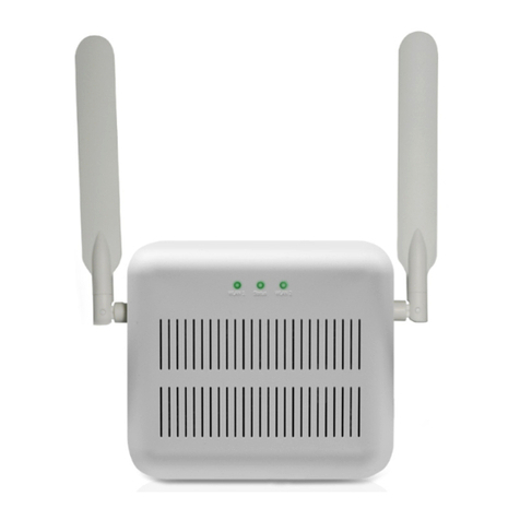
Teldat Connect-4GE User manual
