The dialing sequence can be up to 15 digits.
4. Press the AUTODIAL key where the number is to be
stored.
5. Replace the handset.
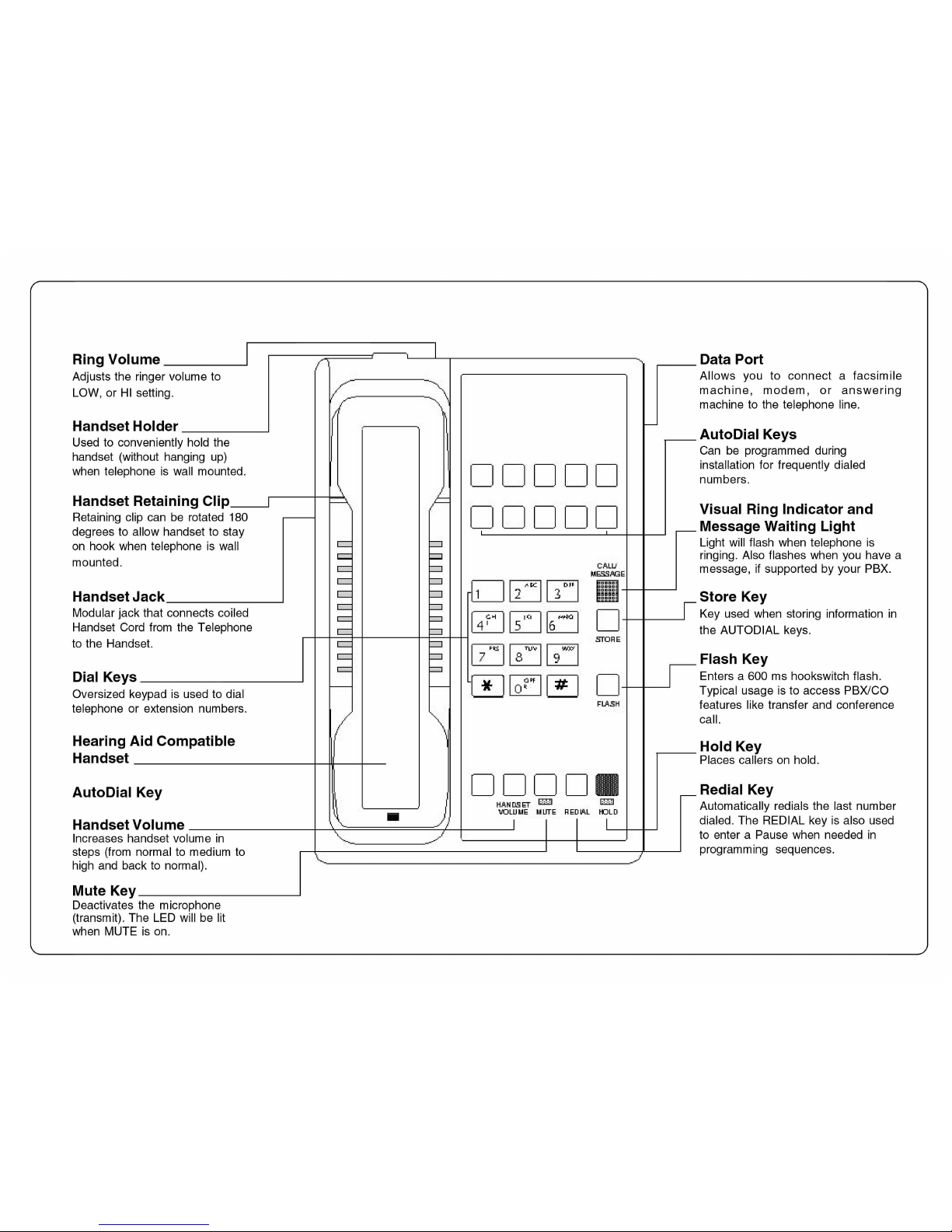
*A 3.6 second pause can be entered in a dialing sequence
by pressing the REDIAL key for each Pause required.
FLASHKEY
Pressing the FLASH key initiates a 600ms hookflash.
Typical usage is to access PBX/CO features like transfer and
conference call.
HANDSETVOLUMEKEY
The handset has three volume levels. When the handset is
first lifted, the handset volume is normal.
To change the HANDSET VOLUME:
Locate the HANDSET VOLUME key at the bottom of the
keypad. Press the key once and the volume level will
increase one level (to medium volume). Press the key once
more and the volume level will increase an additional level
(to high volume).
To put the handset volume back to normal volume, press the
handset volume key again.
MUTEKEY
Press the Mute key, the red LED below the MUTE key will
light. The party on the other end will not hear you when the
MUTE key is depressed. Pressing the MUTE key again will
release mute. This will allow the other party to hear you.
REDIALING
To redial the last telephone number dialed:
1. Lift the handset, listen for dial tone.
2. Press the REDIAL key, the BTX4510 will dial the last
number dialed.
PLACING CALLS ON HOLD
Press the red HOLD key. The red HOLD LED will light. The
handset can be replaced in the cradle without disconnecting
the call.
To retrieve a call from HOLD, lift the handset from the cradle
position. If handset is not in the cradle, simply depress the
HOLD key.
REQUIREMENTS OF PART 68 - FCC RULES
This device has been granted a registration number by the Federal Communications Commission,
under Part 68 rules and regulations for direct connection to the telephone lines. In order to comply
with these FCC rules, the following instructions must be carefully read and applicable portions
followed completely:
1. Direct connection to the telephone lines may be made only through the standard modular cord
furnished, to the utility installed jack. No connection may be made to party or coin phone lines.
On the bottom of the phone is a label that contains among other information, the FCC Registration
Number and the Ringer Equivalence number (REN) for this equipment. If requested this
information must be provided to the telephone company. The USOC Jack for this equipment is
RJ11C.
2. The telephone company, under certain circumstances, may temporarily discontinue and make
changes in facilities and services which may affect the operation of the users' equipment: however,
the user shall be given adequate notice in writing to allow the user to maintain uninterrupted
service.
3. In certain circumstances, it may be necessary for the telephone company to request information
from you concerning the equipment which you have connected to your telephone line. Upon
request of the telephone company, provide the FCC registration number and the ringer equiva-
lence number of the equipment which is connected to your line; this information will be found on
the device.
4. If any of your telephone equipment is not operating properly, you should immediately remove
it from the telephone line. It may cause harm to the telephone network.
5. If the telephone company notes a problem, they may temporarily discontinue service. When
practical, they will notify you in advance of disconnection. If advance notice is not feasible, the
telephone company must; promptly notify you of such temporary discontinuance; afford the
opportunity to correct the condition; inform you of your rights to bring a complaint to the FCC under
their rules.
6. Repairs to the device may be made only by the manufacturer or an authorized service agency.
This applies at any time during and after warranty. If unauthorized repair is performed, registration,
connection to the telephone lines and remainder of warranty period all become null and void.
7. This equipment is hearing aid compatible.
REQUIREMENTS OF PART 15 - FCC RULES
NOTE: This equipment has been tested and found to comply with the limits for a Class B digital
device, pursuant to Part 15 of the FCC Rules. These limits are designed to provide reasonable
protection against harmful interference in a residential installation. This equipment generates,
uses, and can radiate radio frequency energy and, if not installed and used in accordance with the
instruction, may cause harmful interference to radio communications. However, there is not a
guarantee that interference will not occur in a particular installation. If this equipment does cause
harmful interference to radio or television reception, which can be determined by turning the
equipment off and on, the user is encouraged to try to correct the interference by one or more of
the following measures: -Move the telephone away from the receiver. -Consult the dealer or an
experienced radio/TV technician for help. Any changes made by the user not approved by the
manufacturer can void the user's authority to operate the telephone.
INDUSTRYOFCANADAREQUIREMENTS
Notice: The Industry Canada label identifies certified equipment. This certification means that the
equipment meets certain telecommunications network protective operational and safety require-
ments as prescribed in the appropriate Terminal Equipment Technical Requirements documents.
The department does not guarantee the equipment will operate to the users satisfaction.
Before installing this equipment, users should ensure that it is permissible to be connected to the
facilities of the local telecommunications company. The equipment must also be installed using an
acceptable method of connection.
The customer should be aware that compliance with the above conditions may not prevent
degradation of service in some situations.
Repairs to certified equipment should be coordinated by a representative designated by the supplier.
Any repairs or alterations made by the user to this equipment, or equipment malfunctions, may give
the telecommunications company cause to request the user to disconnect the equipment.
Users should ensure for their own protection that the electrical ground connections of the power utility,
telephone lines, and internal metallic water pipe systems, if present, are connected together. This
precaustion may be particularly important in rural areas.
Caution: Users should not attempt to make such connections themselves, but should contact the
appropriate electric inspection authority or electrician, as appropriate.
The Ringer Equivalence Number (REN) of this device is Z.
Notice: The Ringer Equivalence Number (REN) assigned to each terminal device provides an
indication of the maximum number of terminals allowed to be connected to a telephone interface. The
termination on an interface may consist of any combination of devices subject only to the requirement
that the sum of the Ringer Equivalence Numbers of all the devices does not exceed 5. This telephone
connects to the telephone network under the connecting arrangement code CA11A.
TELEDEX CORPORATION
6311 San Ignacio Avenue
San Jose, CA 95119
Telephone: (408) 363-3100
Fax:(408)363-3136