TABLE OF CONTENTS
3
Table of Contents
SAFETY INSTRUCTIONS .................................................. 5
GETTING STARTED .......................................................... 8
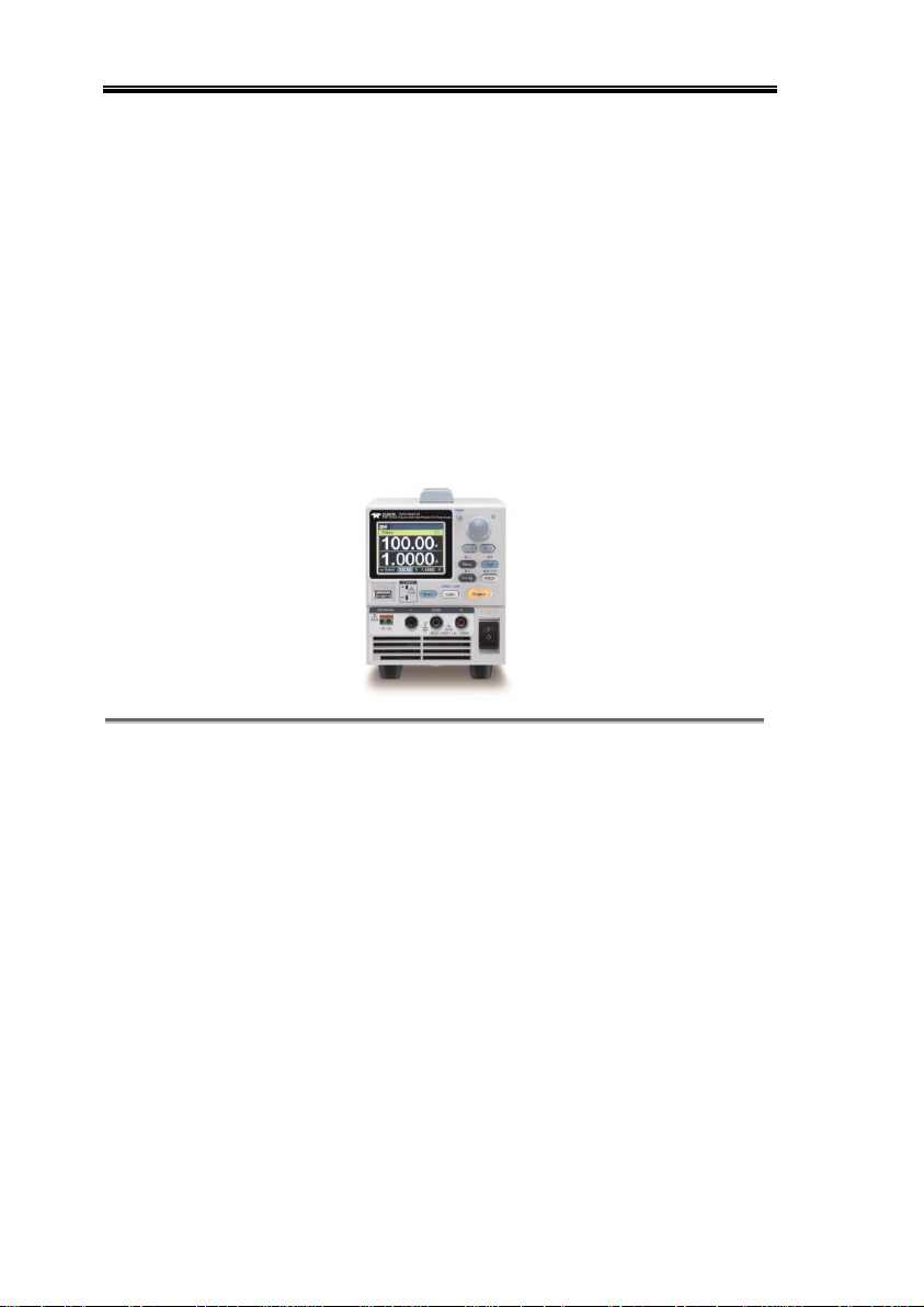
T3PS Series Overview ................................................ 9
Appearance.............................................................. 11
Theory of Operation ................................................ 19
OPERATION .................................................................. 29
Set Up ..................................................................... 30
Menu Tree ............................................................... 39
Basic Operation ....................................................... 45
Sequence Test .......................................................... 72
MENU CONFIGURATION..............................................107
Configuration Overview ......................................... 108
Output................................................................... 108
Measurement ........................................................ 112
EXT Control ........................................................... 115
TRIG Control ......................................................... 120
PWR On Config...................................................... 126
Constant PWR........................................................ 127
Temperature .......................................................... 130
Save/Recall ............................................................ 134
Interface ................................................................ 137
Utility .................................................................... 143
APP........................................................................ 150
Calibration ............................................................. 157
ANALOG CONTROL......................................................158
Analog Remote Control Overview .......................... 159
Remote Monitoring................................................ 175