Teledyne T3PS36006 User manual


This manual contains proprietary information, which is protected by
copyrights. All rights are reserved. No part of this manual may be
photocopied, reproduced or translated to another language without
prior written consent of Teledyne LeCroy company.
The information in this manual was correct at the time of printing.
However, Teledyne LeCroy continues to improve products and
reserves the rights to change specification, equipment, and
maintenance procedures at any time without notice.

TABLE OF CONTENTS
3
Table of Contents
SAFETY INSTRUCTION .................................................... 4
OVERVIEW ...................................................................... 8
T3PS36006 Main Features....................................... 9
Front Panel Overview.............................................10
Rear Panel Overview ..............................................13
SETUP ........................................................................... 14
Installation Location ..............................................15
Power Up ...............................................................16
Over Voltage Protection Setup ...............................17
Load Cable Connection ..........................................19
Output On/Off ......................................................20
APPENDIX ..................................................................... 22
Specification..........................................................22

T3PS36006 Quick Start Guide
4
SAFETY INSTRUCTION
This chapter contains important safety instructions
that you must follow when operating T3PS36006
and when keeping it in storage. Read the
following before any operation to insure your
safety and to keep the best condition for
T3PS36006.
Safety Symbols
These safety symbols may appear in this manual or on T3PS36006.
WARNING
Warning: Identifies conditions or practices that
could result in injury or loss of life.
CAUTION
Caution: Identifies conditions or practices that
could result in damage to T3PS36006 or to other
properties.
DANGER High Voltage
Attention Refer to the Manual
Protective Conductor Terminal
Earth (ground) Terminal

SAFETY INSTRUCTION
5
Safety Guidelines
General Guideline
CAUTION
Do not place any heavy object on T3PS36006.
Avoid severe impacts or rough handling that
leads to damaging T3PS36006.
Do not discharge static electricity to T3PS36006.
Do not block or obstruct the cooling fan vent
opening.
Leave a space around T3PS36006, at least 3cm to
the left and right.
Do not perform measurement at circuits directly
connected to Mains (Note below).
Do not disassemble T3PS36006 unless you are
qualified as service personnel.
(Measurement categories) EN 61010-1:2010 specifies the
measurement categories and their requirements as follows.
T3PS36006 falls under category I.
Measurement category IV is for measurement performed at the
source of low-voltage installation.
Measurement category III is for measurement performed in the
building installation.
Measurement category II is for measurement performed on the
circuits directly connected to the low voltage installation.
Power Supply
WARNING
AC Input voltage: 115V/230V ±15%, 50/60Hz
Connect the protective grounding conductor of
the AC power cord to an earth ground, to avoid
electrical shock.
Fuse
WARNING
Fuse type: T10A/250V
Make sure the correct type of fuse is installed
before power up.

T3PS36006 Quick Start Guide
6
To ensure fire protection, replace the fuse only
with the specified type and rating.
Disconnect the power cord before fuse
replacement.
Make sure the cause of fuse blowout is fixed
before fuse replacement.
Cleaning
T3PS36006
Disconnect the power cord before cleaning.
Use a soft cloth dampened in a solution of mild
detergent and water. Do not spray any liquid.
Do not use chemical or cleaner containing harsh
material such as benzene, toluene, xylene, and
acetone.
Operation
Environment
Location: Indoor, no direct sunlight, dust free,
almost non-conductive pollution (Note below)
Relative Humidity: < 80%
Altitude: < 2000m
Temperature: 0°C to 40°C
(Pollution Degree) EN 61010-1:2010 specifies the pollution degrees
and their requirements as follows. T3PS36006 falls under degree 2.
Pollution refers to “addition of foreign matter, solid, liquid, or
gaseous (ionized gases), that may produce a reduction of dielectric
strength or surface resistivity”.
Pollution degree 1: No pollution or only dry, non-conductive
pollution occurs. The pollution has no influence.
Pollution degree 2: Normally only non-conductive pollution
occurs. Occasionally, however, a temporary conductivity caused
by condensation must be expected.
Pollution degree 3: Conductive pollution occurs, or dry, non-
conductive pollution occurs which becomes conductive due to
condensation which is expected. In such conditions, equipment
is normally protected against exposure to direct sunlight,
precipitation, and full wind pressure, but neither temperature
nor humidity is controlled.
Storage
environment
Location: Indoor
Relative Humidity: < 70%
Temperature: −10°C to 70°C

SAFETY INSTRUCTION
7
Power cord for the United Kingdom
When using T3PS36006 in the United Kingdom, make sure the
power cord meets the following safety instructions.
NOTE: This lead/appliance must only be wired by competent persons
WARNING: THIS APPLIANCE MUST BE EARTHED
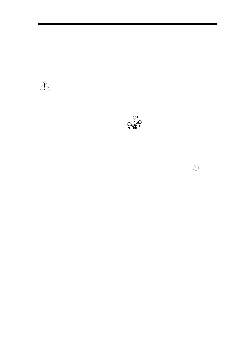
IMPORTANT: The wires in this lead are coloured in accordance with
the following code:
Green/ Yellow:
Earth
Blue:
Neutral
Brown:
Live (Phase)
As the colours of the wires in main leads may not correspond with the
colours marking identified in your plug/appliance, proceed as follows:
The wire which is coloured Green & Yellow must be connected to the
Earth terminal marked with the letter E or by the earth symbol or
coloured Green or Green & Yellow.
The wire which is coloured Blue must be connected to the terminal
which is marked with the letter N or coloured Blue or Black.
The wire which is coloured Brown must be connected to the terminal
marked with the letter L or P or coloured Brown or Red.
If in doubt, consult the instructions provided with the equipment or
contact the supplier.
This cable/appliance should be protected by a suitably rated and
approved HBC mains fuse: refer to the rating information on the
equipment and/or user instructions for details. As a guide, cable of
0.75mm2should be protected by a 3A or 5A fuse. Larger conductors
would normally require 13A types, depending on the connection
method used.
Any moulded mains connector that requires removal /replacement
must be destroyed by removal of any fuse & fuse carrier and disposed
of immediately, as a plug with bared wires is hazardous if a engaged in
live socket. Any re-wiring must be carried out in accordance with the
information detailed on this label.

T3PS36006 Quick Start Guide
8
OVERVIEW
This chapter describes T3PS36006 in a nutshell,
including its main features and front / rear panel
introduction. After going through the overview,
follow the Setup chapter (page 14) to properly
power up and set operation environment.
T3PS36006 Main Features ....................................... 9
Front Panel Overview ............................................ 10
Rear Panel Overview ............................................. 13

OVERVIEW
9
T3PS36006 Main Features
Performance
Low noise (≤ 50dB, Cooling fan controlled by
Heatsink temperature)
High efficiency power conversion, minimum
70% with full load
Fast Output On/Off response (≤100ms)
Low temperature coefficient
(≤100ppm/°C+3mV, ≤150ppm/°C+3mA)
Compact size, light weight (6kg)
Operation
Constant voltage operation
Constant current operation
Tracking Series operation
Tracking Parallel operation
Output On/Off control
3 outputs with full Voltage control
Output range selection for CH1 and CH2,
60V/3A or 30V/6A
LED display
Protection
Over voltage protection (OVP)
Overload protection
Reverse polarity protection
Interface
Remote control output On/Off terminal

T3PS36006 Quick Start Guide
10
Front Panel Overview
VOLTAGE
VOLTAGE CURRENT
CURRENT
OVER LOAD
CH3
VOLTAGE
OUTPUT CH2 CH1
SLAVE MASTER
TRACKING
INDEP.
SERIES
PARALLEL
C.V.
O.V.P.
SET C.V.
C.C.
TRIP C.C.
PAR.
CH2 CH1 CH3GND
0.1-5V, 3A
0-60V, 3A
0-30V, 6A
0-60V, 3A
0-30V, 6A
ON / OFF
POWER
V
Dual-Range DC Power Supply
CH1
CH3
AVA
CH1 / CH3CH2
60V/3A
30V/6A
T3PS36006
CH2 Meter
Output Range
Switch CH1/CH3
Meter Switch
CH1/3 Meter
Output
Key
Power
Switch
OVP
Indicator
CH2 Output
Knob
CH2
Indicator
CH2 Output
Terminal
Ground
Terminal
Tracking Mode
Switches
CH3 Overload
Indicator
CH3 Voltage
Knob
CH3 Output
Terminal
CH1 Output
Knob
CH1
Indicator
CH1 Output
Terminal
Power switch
POWER
Turns On or Off the main
power.
OVP indicator
O.V.P.
SET
TRIP
Turns green during the OVP setup.
Turns red (tripped) when the
output Voltage exceeds the setting.
Output Key
OUTPUT
ON / OFF
Turns the output On (green) or Off
(gray), all three channels at once.
Output range
switch
60V/3A
30V/6A
Selects the output range, 60V/3A
or 30V/6A.
CH2 meter
Displays Channel 2 current (A) and voltage (V).

OVERVIEW
11
CH
Tracking mode
switches
TRACKING
INDEP.
SERIES
PARALLEL
Activates and selects the tracking
mode.
Independent
Tracking Series
Tracking Parallel
CH1/3 meter +
switch
Displays Channel 1 or Channel 3 current (A) and
voltage (V). The switch on the right selects the
channel 1 (up) or 3 (down).
C1
C3
CH1/ CH3
Channel 3
overload
indicator
OVER LOAD
Turns red when Channel 3 output
exceeds the current rating, 3A.
Channel 3 switches from Constant
Voltage (CV) mode to Constant
Current (CC) mode.
Channel 1/2/3
output terminal
CH3
0.1-5V, 3A
Accepts the load cables.

T3PS36006 Quick Start Guide
12
Channel 1
CV/CC indicator
C.V.
C.C.
Turns green when operating in
Constant Voltage (CV) mode, red
in Constant Current (CC) mode.
Channel 2
CV/CC/PAR
indicator
C.V.
C.C.
PAR.
Independent mode:
Turns green in Constant Voltage
(CV) mode, red in Constant
Current (CC) mode.
When operating in the Tracking
Parallel mode, the Channel 2
indicator always stays red (PAR).
Channel 1 indicator shows the
CV/CC status.

OVERVIEW
13
Rear Panel Overview
EFORE REPLACING FUSE
DISCONNECT POER CORD
30V
FUSE RATING
AS SPECIFIED
50V
T10A
REPLACE FUSE
115V
AC
50/60
550 ATTS
900 VA A
C3CC1
O.V.P. SETNORAL
ON
OFF
SER. NO. L
OVP Setting
Point
Remote Control
Terminal Power Cord /
Fuse Socket
Cooling Fan
WARNING
Remote control
terminal
Accepts remote output On/Off
control connection.
OVP setting point
C3CC1
NORAL O.V.P. Set
Activates Over Voltage Protection
(OVP) and sets the protection
threshold for channel 1/2/3.
Power cord / fuse
socket
The power cord socket accepts the
AC mains: 115V/230V, 50/60Hz.
The fuse holder contains the AC
main fuse.

T3PS36006 Quick Start Guide
14
SETUP
This chapter describes how to properly power up
and configure T3PS36006 before the operation.
Installation Location ............................................. 15
Power Up .............................................................. 16
Over Voltage Protection Setup .............................. 17
Load Cable Connection ......................................... 19
Output On/Off ...................................................... 20

SETUP
15
Installation Location
Ventillation space
Leave at least 3cm around T3PS36006, to the left
and right.
> 3cm > 3cm
Cooling fan
opening
The cooling fan is located on the rear panel.
Allocate extra space on the back of T3PS36006 so
that the cooling fan opening would not become
blocked.
Cooling
Fan

T3PS36006 Quick Start Guide
16
Power Up
Power On
Press the Power switch to
turn On the power. The
CH1/CH2 indicators and
meters turn On.
VOLTAGE VOLTAGE
CURRENT CURRENT CH2CH1 SLAVEMASTER
C.V.C.V.
C.C.
C.C. PAR.
VOLTAGE VOLTAGE
CURRENT CURRENT CH2CH1 SLAVEMASTER
C.V.C.V.
C.C.
C.C. PAR.
CH1 / CH 3
CH
CH1 / CH 3
CH
Power Off
Press the Power switch
again to turn Off the
power. After two
seconds, the meters and
indicators turn Off.

SETUP
17
Over Voltage Protection Setup
Background
Over Voltage Protection (OVP) protects T3PS36006
and DUT from excessive output Voltage. The user
sets the maximum output voltage limit before
operation. When the output voltage exceeds this
limit, the indicator shows the over voltage status
and the output is shut off immediately.
OVP setup
1. Slide the rear panel switch to
the “O.V.P. SET” position.
C3CC1
NORAL
O.V.P. Set
2. The OVP indicator on the front
panel turns green, indicating
OVP setup.
O.V.P.
SET
TRIP
3. The Voltage meters show the OVP setting level
instead of the output level. The Current meters
show zero (0.00).
CH1 / CH3 CH1 / CH3
4. Adjust the OVP level using the
rear panel terminal. The
setting on the front panel
meter changes accordingly.
C1
INCREASE
DECREASE
Setting range
Channel 1
1.0V ~ 67.0V
Channel 2
1.0V ~ 67.0V
Channel 3
0.1V ~ 6.0V

T3PS36006 Quick Start Guide
18
*
When setting the OVP for
channel 3, select CH3 meter
using the CH1/CH3 meter
switch.
CH1
CH3
5. When finished, slide the rear
panel switch to the “Normal”
position. The OVP indicator on
the front panel turns Off.
C3CC1
NORAL
O.V.P. Set
O.V.P.
SET
TRIP
O.V.P.
SET
TRIP
When OVP is
activated....
The OVP activates when one of
channel 1/2/3 output voltage
exceeds the OVP setting. The
indicator turns red (tripped), and
the output is shut Off
immediately.
O.V.P.
SET
TRIP
O.V.P.
SET
TRIP
ON / OFF
OUTPUT OUTPUT
ON / OFF

SETUP
19
Load Cable Connection
Standard
accessory
(GTL-104)
1. Turn the terminal
counterclockwise and
loose the screw.
2. Insert the cable
terminal.
0 60V , 3A
0 30V , 6A
2
1
3. Turn the terminal
clockwise and tighten
the screw.
0 60V , 3A
0 30V , 6A
3
Banana plug
Insert the plug into the
socket.
0 60V , 3A
Wire type
When using load cables other than the attached,
make sure they have enough current capacity for
minimizing cable loss and load line impedance.
Voltage drop across a wire should not excess 0.5V.
The following list is the wire current rating at
450A/cm2.
Wire size (AWG)
Maximum current (A)
20
2.5
18
4
16
6
14
10
12
16

T3PS36006 Quick Start Guide
20
Output On/Off
Panel operation
Pressing the Output key once
Turns On the output, all
channels 1/2/3 at once.
ON / OFF
OUTPUT
OUTPUT
ON / OFF
Pressing again turns Off the
output.
ON / OFF
OUTPUT OUTPUT
ON / OFF
Automatic
Output Off
Any of the following actions during output On
automatically turns it Off. They might involve
sudden and harmful change in the output level.
Change the range.
60V/3A
30V/6A
Change the tracking SW between
independent/ series/ parallel.
TRACKING
INDEP.
SERIES
PARALLEL
OVP tripped.
O.V.P.
SET
TRIP
O.V.P.
SET
TRIP
OVP SET mode.
C3CC1
NORAL
O.V.P. Set
Remote control
When in remote control mode,
front panel output control is
disabled.
Table of contents
Other Teledyne Power Supply manuals

Teledyne
Teledyne 913 Operating instructions

Teledyne
Teledyne T3PS3000 User manual

Teledyne
Teledyne HASTINGS 200 Series User manual

Teledyne
Teledyne T3PS20051P User manual

Teledyne
Teledyne Battery-Backed Power Supply Operating instructions

Teledyne
Teledyne T3PS13206P User manual

Teledyne
Teledyne T3PS13206 User manual

Teledyne
Teledyne 3190 Series User manual

Teledyne
Teledyne Power Pod 400 User manual

Teledyne
Teledyne T3PS12415 User manual