manuals.online logo
Brands
  1. Home
  2. •
  3. Brands
  4. •
  5. Televes
  6. •
  7. Amplifier
  8. •
  9. Televes Microkom Series User manual

Televes Microkom Series User manual

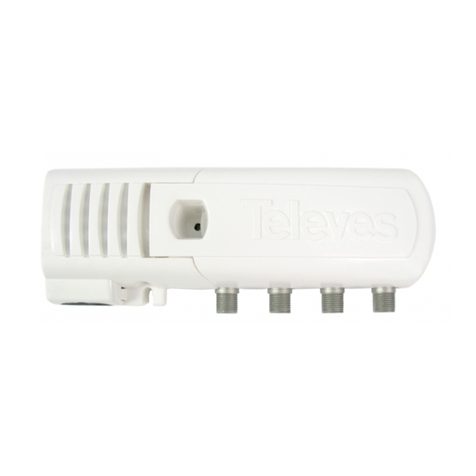
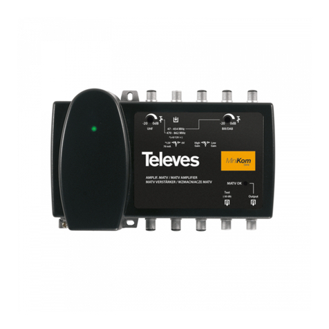
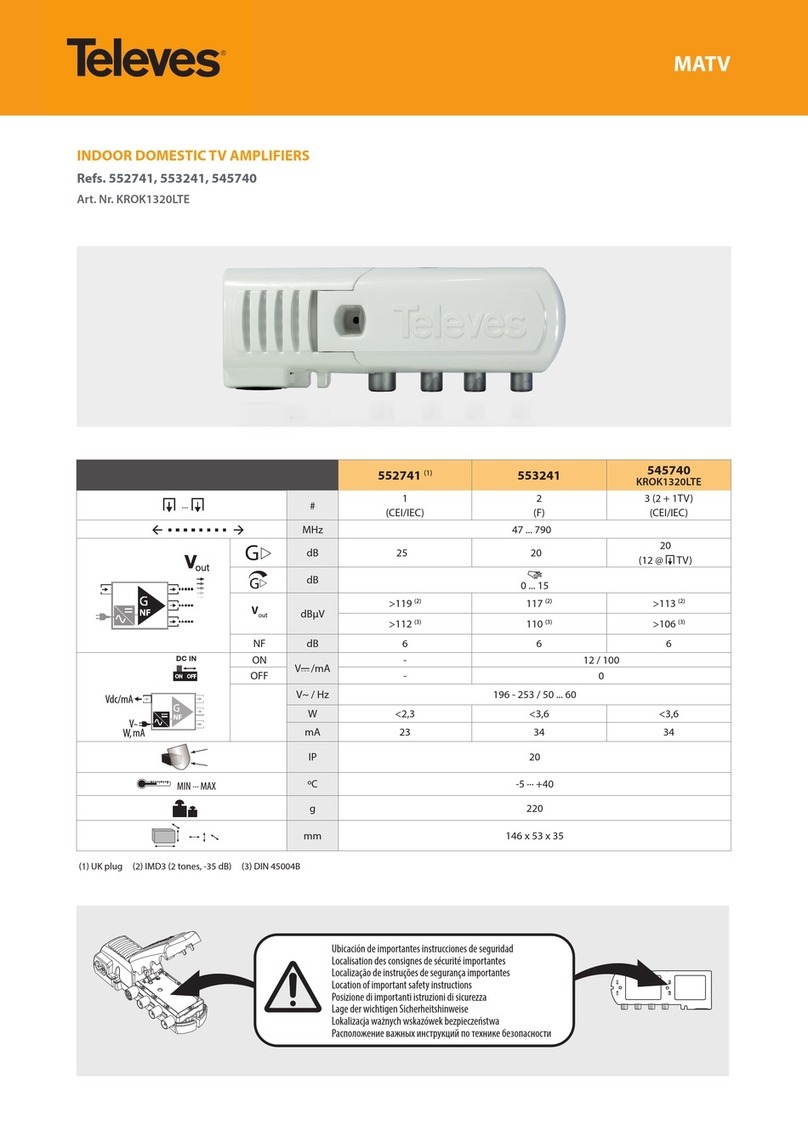
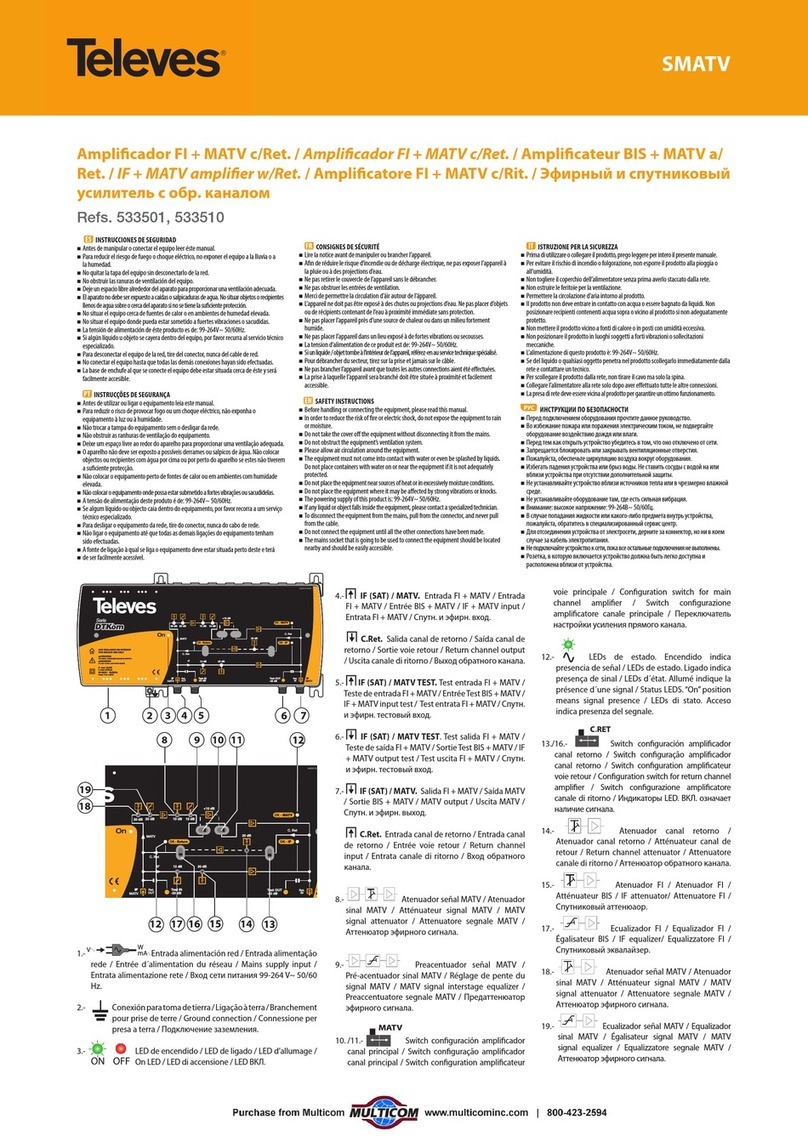
CATV Indoor ampliers. Microkom Series
Refs. 534482, 534483
2022 © Copyright, Televés S.A.U.
DECLARACIÓN DE CONFORMIDAD DECLARATION OF CONFORMITY DECLARAÇÃO DE CONFORMIDADE DECLARATION DE CONFORMITE DICHIARAZIONE DI CONFORMITÀ DEKLARACJA ZGODNOŚCI
KONFORMITÄTSERKLÄRUNG ΠΙΣΤΟΠΟΙΗΤΙΚΟ ΣΥΜΜΟΡΦΩΣΗΣ FÖRSÄKRAN OM ÖVERENSSTÄMMELSE ДЕКЛАРАЦИЯ СООТВЕТСТВИЯ 
https://doc.televes.com
EN Important Safety Instructions
General installation conditions
Before handling or connecting this equipment, please read carefully all warnings and instructions in this manual.
In order to reduce the risk of re or electric shock, do not expose the equipment to rain or in excessively moisture conditions.
Do not open the equipment without disconnecting it from the mains.
Do not obstruct the equipment’s ventilation system.
Please, allow air circulation around the equipment.
The equipment must not come into contact with water or even be splashed by liquids. Do not place containers with water
on or near the equipment if it is not adequately protected.
Do not place the equipment near heat sources, like radiators, stoves, heater or other electronic equipment.
Do not place the equipment where it may be aected by strong vibrations or knocks.
How to use the equipment safely
If any liquid or object falls inside the equipment, please contact a specialized
technician.
.Do not connect the equipment to the mains until all the other connections have been made.
The mains socket that is going to be used to connect the equipment should be located nearby and should be easily
accessible.
Make sure that all power cords, plugs and cables are not pinched or bent sharply to prevent any possibility of damage,
electrical shock or re.
Unplug the unit power cord by gripping the plug only.
Description of the electrical safety symbols
This symbol indicates that the equipment complies with the safety requirements for class II equipment.
This symbol indicates that the equipment complies with the requirements of the CE mark.
Recycling information
The disposal of this product after its useful life must be made as an electronic scrap
in compliance with the current disposal regulations of your district/country.
ES Importantes instrucciones de seguridad
Condiciones generales de instalación
Antes de manejar o conectar este equipo, lea atentamente todas las alertas e instrucciones de este manual.
Con el objeto de reducir el riesgo de fuego o de una descarga eléctrica, no exponga el equipo a la lluvia o a condiciones
excesivamente húmedas.
No abra nunca el equipo sin desconectarlo antes de la red.
No obstruya el sistema de ventilación del equipo y permita que el aire circule alrededor del equipo.
El equipo nunca debe entrar en contacto con el agua o incluso ser salpicado por líquidos. Por ello no sitúe contenedores de
agua sobre o cerca del equipo si este no esta adecuadamente protegido.
No sitúe el equipo cerca de fuentes de calor, como radiadores, estufas, calentadores u otros equipos electrónicos.
No instale el equipo donde pueda estar sometido a fuertes vibraciones o golpes.
Operación segura del equipo
Si cualquier líquido hubiera entrado en el equipo, contacte con un técnico especializado.
No enchufe el equipo a la red eléctrica hasta que todas las demás conexiones hayan sido realizadas.
La toma de corriente a la que esté enchufada el equipo debería estar situada cerca y ser fácilmente accesible.
Asegúresedeque todos los cordones de corriente,clavijasy cables coaxialesnoesténpellizcadosni doblados en exceso, para
prevenir cualquier posibilidad de daño, descarga eléctrica o fuego.
Desenchufe la unidad de la red tirando únicamente de la clavija.
Descripción de Simbología de seguridad eléctrica
Este símbolo indica que el equipo cumple los requerimientos de seguridad para equipos de clase II.
Este símbolo indica que el equipo cumple los requerimientos del marcado CE.
Información de reciclaje
Deseche o retire este equipo de acuerdo con todas las regulaciones locales, estatales y federales.
Responsible party:
Televes USA LLC. Norfolk Tech Center 16596 E. 2nd Avenue Aurora, CO 80011 USA
Telephone: +1 (720) 379 3748 [email protected]
Fabricante / Manufacter:
Televés, S.A.U. Rúa B. de Conxo, 17 15706, Santiago de Compostela, A Coruña (Spain)
12 3 4
1.- Input connector
2.- Test IN -20dB
3.- Test OUT -20dB
4.- Output connector
Class B equipment.
This equipment has been tested and found to comply with the limits for a Class B digital device, pursuant to part 15 of the FCC Rules.These limits are designed to provide reasonable protection against harmful interference in a residential installation.
This equipment generates, uses and can radiate radio frequency energy and, if not installed and used in accordance with the instructions, may cause harmful interference to radio communications. However, there is no guarantee that interference will not occur
in a particular installation. If this equipment does cause harmful interference to radio or television reception, which can be determined by turning the equipment o and on, the user is encouraged to try to correct the interference by one or more of the
following measures:
- Reorient or relocate the receiving antenna.
- Increase the separation between the equipment and receiver.
- Connect the equipment into an outlet on a circuit dierent from that to which the receiver is connected.
- Consult the dealer or an experienced radio/TV technician for help.
CATV Indoor ampliers. Microkom Series
Refs. 534482, 534483
Input & Output description / Descripción Entradas y Salidas
Block diagram / Diagrama de bloques
EN General description
Range of ampliers designed for multimedia distribution in small/medium size buildings.
These ampliers feature forward and passive/active return path with their correponding range of
attenuators and equalizers that provide the optimum adjustment to deliver the right output level in
accordance with the installation needs. Amplier’s setting up is carried out by means of removable
jumpers that allow to select xed stepped values. The use of jumpers allows an easy reading of each
setting.
The active return path is fully congurable by means of plug-in jumpers. Attenuation ranges from 0 to 18
dB in xed steps of 2 dB. The equalizer is an interstage type ranging from 0 to 6 dB in xed steps of 3 dB.
The forward path features both congurable input attenuator and input equalizer by means of jumpers
in steps of 2 dB. Furthermore, it has selectable interstage attenuation and equalization by means of two
double jumpers.
The forward gain is selectable by double jumper, allowing to decrease 0 or 5dB.
Furthermore, it has selectable interstage equalization (tilt), with double jumper allowing 0 or 6 dB
settings.
The amplier is housed within a die-cast enclosure that contributes to reduce the temperature of its
components due to its excellent heat disipation.
An ON/OFF LED indicates when the amplier is connected to mains. On the other hand, a LED inside
indicates if the amplier is being powered.
Once opened (untightening the screw located on its front), an intuitive diagram of blocks explains how
the amplier works to achieve the desired output level.
Open the amplier by untightening the screw located on its front lid.
The amplier block diagram is inside the unit.To set attenuation/equalization, plug-in the jumper into the
required value for the installation.
The forward path features separate interstage equalization and attenuation. Two double jumpers can be
set in two positions, as indicated in the diagram.
Jumper positioned "=" do not attenuates the signal. Jumper positioned "
=
" attenuates the signal by 5 dB.
In the same way you can proceed with the double jumper for the equalization.
Once all settings have been made, close de enclosure and thighten its frontal screw.
Typical applications / Aplicación típica
IN
DS -20 dB -20 dB
OUT
DS
OUT
US
IN
US
ON
ES Descripción general
Gama de amplicadores diseñada para distribución multimedia en edicios de tamaño pequeño/medio.
Estos amplicadores se caracterizan por tener canal principal y canal de retorno, con sus respectivos
ajustes de ecualización y atenuación que permiten un ajuste del nivel de salida óptimo según las necesi-
dades del instalador. Los ajustes del amplicador se realizan mediante puentes insertables que permiten
seleccionar los valores, tanto de atenuación como de ecualización, en saltos de un valor jo. La utilización
de puentes insertables permite una fácil y rápida lectura de los valores ajustados.
El canal de retorno activo es totalmente congurable por medio de puentes. Su margen de atenuación de
señal es de 0-18 dB, en saltos jos de 2 dB. El ecualizador es igualmente congurable y su margen es de
0-6 dB en saltos jos de 3 dB.
El canal principal tiene a su entrada atenuador y ecualizador congurables mediante puentes, en un
margen de 0-18 dB, en saltos jos de 2 dB. Además, tiene la posibilidad de un ajuste de atenuación y
ecualización entre etapas, mediante dos puentes dobles. De acuerdo con la posición del puente al ser
insertado, la atenuación se puede elegir entre 0 ó 5 dB mientras que la ecualización entre 0 ó 6 dB, inde-
pendientemente.
El amplicador está alojado en un chasis de zamak inyectado que contribuye a reducir la temperatura de
sus componentes gracias a su elevada capacidad de disipación del calor.
Un LED en el exterior del chasis indica cuando el amplicador está conectado a la red.
Otro LED situado en su interior indica si le llega alimentación al amplicador.
Abra el amplicador aojando el tornillo que se encuentra en su tapa frontal. Dentro del amplicador
tenemos una ilustración que muestra el diagrama de bloques intuitivo que permite comprender su fun-
cionamiento y realizar los ajustes necesarios para obtener el adecuado nivel de salida. Para ajustar los
valores de atenuación/ecualización, inserte el puente en el valor requerido para la instalación.
El canal principal se caracteriza por poseer ecualización y atenuación independiente entre etapas. Dos
puentes dobles pueden ser insertados en dos posiciones, tal como se indica en el diagrama.
El puente posicionado "=" no atenúa la señal, el puente posicionado "
=
" atenúa la señal en 5 dB.
De la misma forma se procede con el doble puente correspondiente a la ecualización.
Una vez que todos los ajustes se han hecho, cierre el equipo y apriete el tornillo de su tapa frontal.
1 2 3 4
5
6
7
8
9
10
1 Forward path input equalizer 0-18 dB, 2 dB steps /
Ecualizador de entrada canal principal 0-18 dB, pasos
2dB
2 Forward path input attenuator 0-18 dB, 2 dB steps /
Atenuador de entrada canal principal 0-18 dB, pasos
2dB
3 Equalizer 0 or 6 dB / Ecualizador 0 ó 6 dB
4 Forward path interstage attenuator 0 or 5 dB /
Atenuador inter-etapas canal principal 0 ó 5 dB
5 Forward path output / Salida canal principal
6 Return path input / Entrada canal retorno
7 Return path input attenuator 0-18 dB, 2 dB steps /
Atenuador de entrada canal retorno 0-18, pasos 2dB
8 Return path input equalizer 0/3/6 dB /
Ecualizador de entrada canal retorno 0/3/6 dB
9 Forward path input / Entrada canal principal
10 Return path output / Salida canal retorno
11 Return path conguration active/passive /
Conguración canal retorno activo/pasivo
Pin not used / Pin no usado
11 11
Especicaciones técnicas Technical specications 534482 534483
Canal Directo Forward path
Rango de frecuencia Frequency range MHz 54 … 1220
Ganancia Gain
dB
351
Desviación valor nominal Nominal value deviation ± 1
Planicidad Linearity ± 1.5
Atenuador de entrada
(pasos de 2 dB) Input attenuator (2dB steps) 0 ... 18
Atenuador entre etapas Interstage attenuator 0/51
Ecualizador Entrada
(pasos de 2 dB) Input equalizer (2dB steps) 0 ... 18
Ecualizador entre etapas Interstage equalizer 0/6
Figura de ruido Noise gure < 7.5
Tensión
de salida
CSO > 60dB* Output
level
CSO (42 CHs) > 60dB
dBmV
45
CTB > 60dB* CTB (42 CHs) > 60dB 45
Pérdidas de retorno
Return losses
dB >12
Toma de prueba Test socket -20
Canal de retorno Return path
Rango de frecuencia Frequency range MHz 5 ... 422
Ganancia activo/ pasivo Gain active/passive
dB
28/-1
Desviación valor nominal Nominal value deviation ± 1
Planicidad Linearity ± 1
Atenuador de entrada
(pasos de 2 dB) Input attenuator (2dB steps) 0 ... 18
Ecualizador entre etapas Interstage equalizer 0/3/62
Figura de ruido Noise gure < 6
Tensión
de salida
64QAM 4TP (En
cumplimiento de
la norma KBW)
Output
level
64QAM 4TP ( In
compliance with
KBW standard) dBmV 55 (BER: 1.0 e-8)
Pérdidas de retorno Return losses
dB
>12
Toma de prueba Test socket -20
General General
Consumo Power consumption W6,6
Consumo máx. total Max. total consumption mA 107
Tensión de red Mains voltage
V
~
110 - 230
Hz 50-60
Tipo de clavija Plug type
Temperatura de trabajo Operating temperature ºF/ºC +14 . . . +113 /-10 … + 45
Protección descargas
electrostáticas
(EN61000-4-2)
Electrostatic discharges protection
(EN61000-4-2) kV 8
Clase de protección Protection class class II isolation
Índice de protección Protection index IP 20
Conectores RF Connectors RF type F-female
Dimensiones Dimensions (W x H x D) in /mm 7.2 x 3.1 x 1.3 / 185 x 80 x 35
Peso Weight lb /g 0.88 / 400
(1) Gain congurable by means Interstage attenuator 0/5dB.
(2) Active / passive congurable by means plug in jumpers
Technical specications / Especicaciones técnicas
Forward path: 54-1002 MHz
Return path: 5-42 MHz
Forward path: 54-1220 MHz
Return path: 5-42 MHz
Forward path: 54-1220 MHz
Return path: 5-42 MHz
This manual suits for next models

2

Other Televes Amplifier manuals

Televes 5338 User manual

Televes

Televes 5338 User manual

Televes avant 7 User manual

Televes

Televes avant 7 User manual

Televes MSV411G User manual

Televes

Televes MSV411G User manual

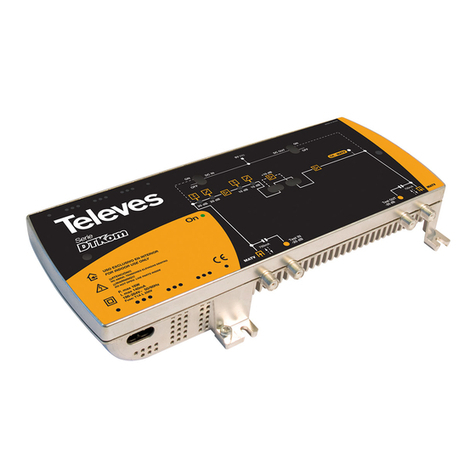
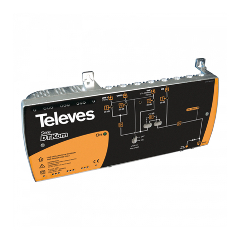
Televes DTKom Series User manual

Televes

Televes DTKom Series User manual

Televes SmartKom 531981 User manual

Televes

Televes SmartKom 531981 User manual

Televes AvantX Series User manual

Televes

Televes AvantX Series User manual

Televes T.0X Series Installation guide

Televes

Televes T.0X Series Installation guide

Televes 552280 User manual

Televes

Televes 552280 User manual

Televes 539201 User manual

Televes

Televes 539201 User manual

Televes DTKom Series Installation instructions

Televes

Televes DTKom Series Installation instructions

Televes 5310 User manual

Televes

Televes 5310 User manual

Televes AVANT9BASIC User manual

Televes

Televes AVANT9BASIC User manual

Televes NANOKOM Series User manual

Televes

Televes NANOKOM Series User manual

Televes OLTWDMA32 User manual

Televes

Televes OLTWDMA32 User manual

Televes 5605 User manual

Televes

Televes 5605 User manual

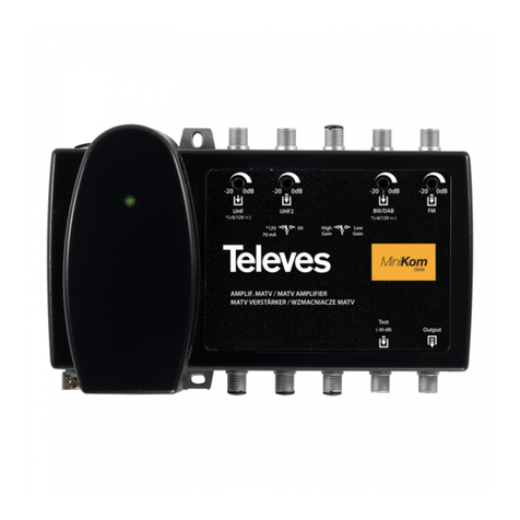
Televes Minikom Series User manual

Televes

Televes Minikom Series User manual

Televes 7344 User manual

Televes

Televes 7344 User manual

Televes Avant User manual

Televes

Televes Avant User manual

Televes OVERLIGHT 2x User manual

Televes

Televes OVERLIGHT 2x User manual

Televes MiniCom Series User manual

Televes

Televes MiniCom Series User manual

Televes 537302 User manual

Televes

Televes 537302 User manual

Televes 545901 User manual

Televes

Televes 545901 User manual

Televes Avant HD User manual

Televes

Televes Avant HD User manual

Televes avant 7 User manual

Televes

Televes avant 7 User manual

Popular Amplifier manuals by other brands

SWR Strawberry Blonde owner's manual

SWR

SWR Strawberry Blonde owner's manual

QSC GXD Series quick start guide

QSC

QSC GXD Series quick start guide

CSI Dual Band BDA product manual

CSI

CSI Dual Band BDA product manual

Philips Amplifier user manual

Philips

Philips Amplifier user manual

Ocean Matrix OMX-ADA6 instruction manual

Ocean Matrix

Ocean Matrix OMX-ADA6 instruction manual

Dorchase DA803S user guide

Dorchase

Dorchase DA803S user guide

Absolute Measurement L-ANV-0-0-R-AC instruction manual

Absolute Measurement

Absolute Measurement L-ANV-0-0-R-AC instruction manual

Omron E3NX-MA Series instruction sheet

Omron

Omron E3NX-MA Series instruction sheet

Hama HA201 operating instructions

Hama

Hama HA201 operating instructions

Harman Crown I-Tech HD Series Operation manual

Harman

Harman Crown I-Tech HD Series Operation manual

icon Audio Stereo 50 instruction manual

icon Audio

icon Audio Stereo 50 instruction manual

Sony XM-2351 operating instructions

Sony

Sony XM-2351 operating instructions

Ground Zero PLUTONIUM SERIES owner's manual

Ground Zero

Ground Zero PLUTONIUM SERIES owner's manual

Marshall Amplification Acoustic Soloist AS80R Handbook

Marshall Amplification

Marshall Amplification Acoustic Soloist AS80R Handbook

Pepperl+Fuchs 2/208 manual

Pepperl+Fuchs

Pepperl+Fuchs 2/208 manual

PRESONUS DigiTube Single-Channel Tube user manual

PRESONUS

PRESONUS DigiTube Single-Channel Tube user manual

Louroe Electronics DG-25III Installation and operating instructions

Louroe Electronics

Louroe Electronics DG-25III Installation and operating instructions

RCF ES3160 Brochure & specs

RCF

RCF ES3160 Brochure & specs

manuals.online logo
manuals.online logoBrands
  • About & Mission
  • Contact us
  • Privacy Policy
  • Terms and Conditions

Copyright 2025 Manuals.Online. All Rights Reserved.