Tenma 72-3545 User manual

1
200A True RMS Fork Meter
Models: 72-3545

2
CONTENTS
Page Number Details
3 What’s Included
3 Important Safety Information
4 Product Overview
4 SELECT Button
4 REL Button
5 ZERO Button
5 HOLD Button
5 Backlight Button
6 Torch Button
6General Specication
6 Environmental Limit
7Electrical Specication
7Measuring AC Current Specication
7Measuring DC Current Specication
7Measuring AC Voltage Specication
7Measuring DC Voltage Specication
8Measuring Resistance Specication
8Conductivity Testing Specication
8Diode Measurement Specication
8Measuring Capacitance Specication
8Induced Voltage Measurement (NCV) Specication
9 Measurement Operations - Measuring AC Current
9 Measuring DC Current
10 Measuring AC Voltage
10 Measuring DC Voltage
11 Measuring Resistance
11 Conductivity Testing
12 Diode Measurement
12 Capacitance Measurement
13 Measuring Induced Voltage (NCV)
13 Maintenance
13 Replacing the Batteries

3
IMPORTANT SAFETY INFORMATION
Please read these instructions carefully before use and retain for future
reference.
• When using electrical appliances basic safety precautions should always be
followed.
• Before each use, check the Meter and probes for any damage. If you notice any
damage to the probe or the instrument, do not use the Meter.
• Do not use the Meter without the rear cover or battery cover, otherwise there is a
severe risk of shock.
•When carrying out measurements, keep your ngers behind the line, ensuring you
do not touch any bare wires and connectors, an unused input terminal or circuits
under measurement, in order to prevent electric shock.
• Before any measurement, ensure that the dial switch is in the correct position. Do
not rotate the dial during measurement, in order to prevent damage to the Meter.
• Do not apply 1000V DC/ 750V AC or above voltage between the meter terminal
and grounding, in order to prevent electric shock or damage to the Meter.
• Use extra care when measuring DC voltage of higher than 42V or 30V AC RMS as
there may be danger of an electric shock.
• Do not measure voltage or current higher than the allowable input. When the
range of the value to be measured is unknown, set the function range switch to the
maximum range position.
• Before measuring resistance, diode or circuit on-off, cut off all the power supplies
in the circuit and discharge all capacitors, otherwise it may lead to incorrect
measurement results.
• When the low battery symbol appears on the LCD, replace the batteries as soon
as possible, in order to ensure precise measurements.
• There are no user-serviceable parts in the meter. Do not attempt to change the
internal wiring of the Meter, to prevent causing any damage.
• Do not use or store the Meter in an environment of high temperature, high
humidity, inammable nature and where an explosive or strong electro-magnetic
eld exists.
• When cleaning, use a dry cloth for the outer shell of the Meter.
• Do not use any chemicals, abrasives or solvents that could damage the Meter.
WHAT’S INCLUDED
• Fork Meter
• One pair of probes
• One zip bag
• One user manual

4
PRODUCT OVERVIEW
1. Clamp head - the sensing device for AC/DC measurement.
Fix the wire into the designated position to measure the
current through the wire.
As the head may touch the live wire at the time of the
measurement, keep your hand below the clamp head.
2. Clamp body - hold the middle of the clamp body and do not
exceed the protective bafe at the joining section between the
upper part of the clamp body and the clamp head.
3. Function dial - used for the start-up and selection of basic
measurement functions. The salient point on the function dial
indicates the present gear position.
4. Function buttons - used for the selection of key functions,
including SELECT, REL/ZERO, HOLD/ and TORCH .
5. Display screen - used to display measurement data and
function symbols. The screen also has the backlight function,
which enables you to measure in low-light environments.
6. Measurement at input terminal - it is at the insertion
port of the probe that the voltage, resistance, capacitance and other parameters are
measured.
SELECT BUTTON
SELECT: function selection button, which works at AC/DC, ACV/DCV and RES/CNT/
DIO/CAP functions.
• When the function dial is switched to AC/DC, it defaults to AC function. Press the
SELECT button to switch between AC and DC functions.
• When the function dial is switched to ACV/DCV it defaults to ACV function. Press
the SELECT button to switch between ACV and DCV functions.
• When the function dial is switched to the RES/CNT/DIO/CAP function it defaults to
the RES function. Press the SELECT button to switch to the CNT function, press
again to access the DIO function and then again to switch to the CAP function.
REL BUTTON
REL: measurement button of relative value, which works at other functions except from
CNT, DIO, NCV and DC functions.
• Press REL under normal measurement mode to switch to relative value measuring
mode.
• Under relative value measuring mode, it will show Dn-Df on the display screen
and Df on the sub-display screen, of which Df is the last measured value (relative
value) and Dn is the current measured value.
•It will display “REL ∆” at the top left of the display screen, which indicates it has

5
ZERO BUTTON
HOLD BUTTON
BACKLIGHT BUTTON
ZERO: base reset button. This function is used with REL and works at the DC function.
• Since the clamp head of the meter generates the induced voltage due to earth
magnetic eld induction when it does not measure any signal, the base number
exists at DC gear generally and varies from the placement position and direction of
the Meter.
• It is necessary to deduct the base number at the time of DC measurement.
• Press the ZERO button under DC function to enter reset mode and deduct the
base number during DC measurement.
• Under reset mode, it will display Dn-Df on the main display screen, of which Df is
the DC base number and Dn is the current measured value.
•Meanwhile, it will display the “ZERO” symbol at the top left of the display screen,
which indicates it has entered reset mode.
• By pressing the ZERO button again under reset mode, it will update Df again and
display the updated Dn-Df.
• To exit the reset function either press and hold the ZERO button, turn the function
dial, or press SELECT.
• Press the HOLD button under reset mode, it will enter data-hold mode and the
Meter will not update the measurement data. When you exit reset mode, “hold”
state will be cancelled also.
HOLD: the data hold button works with all functions.
• To enter data-hold mode, press the HOLD button under normal measurement
mode.
• The Meter will not update the measurement data and the displayed value will be
locked and remain unchanged.
•It will display the “H” symbol at the top left of the display screen, which indicates it
has entered data-hold mode.
• If you wish to exit data-hold mode either press HOLD, turn the function dial or
press SELECT.
entered relative value measuring mode.
• You can return to normal operation mode by pressing the REL button again, or
pressing SELECT for a function switch.
•Press the HOLD button under relative value measuring mode and it will enter data-
hold mode as well and the Meter will not update the measurement data. When you
exit relative value measuring mode, “hold” state will be cancelled also.
• Press and hold the button to turn on the backlight and enter low-light mode,
which means the backlight is bright enough for basic reading.
• Press and hold the button again to enter the high-light mode, under which the
backlight is brighter and the contrast is clearer.
• Press and hold the button again to turn off the backlight.
6
TORCH BUTTON
• To switch on the LED light ensure the Meter is on and simply press the torch
button on the side of the Meter.
• Press the same button to turn off the light.
GENERAL SPECIFICATION
LCD Max. display 5999
Polarity display Automatic positive and negative
Overload display “OL” or “-OL”
Battery voltage <2.4V means the low battery symbol will display
Sampling rate Approx. 3 times per second
Sensor types Hall effect sensor for DC/AC measurement
Measured position error
When measuring current, ±1% additional error
may occur because it fails to put the source to be
measured into the centre position of the probe.
Impact resistant strength 1m high impact can be borne
Max. opening dimension of
clamp head Diameter of 14.7mm
Max. dimension of current
wire Diameter of 14.7mm
Electromagnetic eld effect When an electromagnetic eld interference exists, it
may display unstable or incorrect readings
Power requirements 2 x AA 1.5V batteries (not included)
Auto-off function 15 minutes
Dimensions 210mm x 53mm x 35mm
Weight (approx.) 163.7g
ENVIRONMENTAL LIMIT
Working environment Indoor
Altitude <2000m
Safety requirements IEC61010-1, IEC61010-2-032, CAT II 1000V,
CAT III 600V
Pollution degree 2
Operating temperature and
humidity
0°C-30°C (<80%RH), 30C-40°C (<75%RH),
40°C-50C (<45%RH)
Storage temperature and humidity -20C-+60°C (<80%RH)

7
ELECTRICAL SPECIFICATION
Accuracy ± (% reading + word count), calibration period is one year
Ambient temperature 23°C ± 5°C
Ambient humidity ≤80%RH
Temperature coefcient 0.1 x (accuracy)/°C
AC CURRENT SPECIFICATION
Measurement range Resolution ratio Accuracy Overload protection
200.0A 0.1A ±(2.5% + 5) 200A
• Main display: true virtual value current.
• Frequency response: 50Hz - 60Hz.
DC CURRENT SPECIFICATION
Measurement range Resolution ratio Accuracy Overload protection
200.0A 0.1A ±(2.5% + 5) 200A
• The DC base number can be cleaned up by pressing the ZERO button.
AC VOLTAGE SPECIFICATION
Measurement range Resolution ratio Accuracy Overload protection
6.000V 0.001V ±(1.2% + 5)
1000V DC / 750V AC
60.00V 0.01V ±(1.2% + 3)
600.0V 0.1V
750V 1V ±(1.5% + 5)
• Main display: true virtual value voltage.
•Input impedance: ≥10MΩ.
• Frequency response: 45 - 400Hz.
•(50 - 100Hz when ≤400mV).
DC VOLTAGE SPECIFICATION
Measurement range Resolution ratio Accuracy Overload protection
6.000V 0.001V
±(0.8% + 3) 1000V DC / 750V AC
60.00V 0.01V
600.0V 0.1V
1000V 1V ±(1.0% + 5)
•Input impedance ≥10MΩ.

8
RESISTANCE SPECIFICATION
Measurement range Resolution ratio Accuracy Overload protection
600.0Ω 0.1Ω ±(1.2% + 2)
1000V DC / 750V AC
6.000KΩ 0.001kΩ
±(1.0% + 2)60.00KΩ 0.01kΩ
600.0KΩ 0.1kΩ
6.000MΩ 0.001MΩ ±(1.2% + 2)
60.00MΩ 0.01MΩ ±(1.5% + 5)
CONDUCTIVITY TESTING SPECIFICATION
Measurement
range
Resolution
ratio Accuracy Overload
protection
600.0Ω 0.1Ω <10Ω, the buzzer will ring
>10Ω, the buzzer will not ring 1000V DC / 750V AC
• Open circuit voltage is about 1.2V.
DIODE MEASUREMENT SPECIFICATION
Measurement range Resolution ratio Accuracy Overload protection
6.000V 0.001V 0.5V - 0.8V 1000V DC / 750V AC
• Open circuit voltage is about 3.3V.
CAPACITANCE SPECIFICATION
Measurement range Resolution ratio Accuracy Overload protection
60.00nF 0.01nF
±(4.0% + 20)
1000V DC / 750V AC
600.0nF 0.1nF
6.000µF 0.001nF
60.00µF 0.01µF
600.0µF 0.1µF
6.000mF 0.001mF ± 10%
60.00mF 0.01mF For reference only
INDUCED VOLTAGE MEASUREMENT (NCV) SPECIFICATION
Measurement range Accuracy
NCV Induced voltage ≥ 100Vrms,
Distance ≤ 10mm (LED flashes and the buzzer sounds).

9
MEASUREMENT OPERATIONS - MEASURING AC CURRENT
• Set the measuring function range of AC current
by rotating the dial to A. The meter will be
within the measuring function range of AC current
as default.
• Clamp the instrument to the input current signal
to be tested.
• Clamp a single current lead to be tested and
keep it at the bottom of the “U” clamp head.
• The clamp meter will automatically select the
proper range and display the true virtual value of
AC current in the centre of the screen.
• Frequency response range: 50Hz-60Hz.
• Warning: the largest measuring current
must not be greater than 200A AC during the
measurement of AC current.
MEASURING DC CURRENT
• Set the measuring function range of DC current
by rotating the dial to A. The Meter will be
within the measuring function range of DC current
as default.
• Press the SELECT button to switch into the
measuring function range of DC current.
• Clear the base number of the measuring range of
DC current.
• As the clamp head sensor reacts to terrestrial
magnetism and surrounding magnetic eld, there
generally exists a base number even without
measuring.
• Therefore, before measuring DC current, the
base number should be cleared by pressing the
ZERO button.
• Measurements must be conducted after the base number is cleared and the
measured value returns to zero.
• Clamp the instrument to the input current signal to be tested.
•Clamp the single current lead to be tested and keep it at the bottom of the “U”
clamp head.
• The Meter will automatically select the proper range.
• If the current direction is in the same direction as that as that of the clamp head,
it will display the positive value of AC current in the centre of the display screen,
otherwise it will display the negative current value.
• Warning: the largest measuring current must not be greater than 200A DC during
measurement of DC current.
D
D

10
MEASURING AC VOLTAGE
• Insert the black probe into the “COM” input and
the red probe into the “V Ω” input.
• Set the measuring function range of AC voltage
by rotating the dial to V.
• The Meter will be within the measuring function
range of AC voltage as default.
• Connect the voltage to be tested and put the red
and black probes at two sides of the voltage to be
tested. The clamp meter will automatically select
the correct range.
• The centre of the screen will display the current
true visual value of AC voltage.
• When the voltage value exceeds 30V AC, the
screen will display the high-voltage alarm signal
to warn against a shock hazard.
Note: frequency response scope: 45Hz - 400Hz.
• Warning: AC voltage measuring range must not
be greater than 750V AC.
MEASURING DC VOLTAGE
• Insert the black probe into the “COM” input and
insert the red probe into the “V Ω” input, ready for
measurement.
• Set the measuring function range by rotating the
dial to V.
• Press the SELECT button to switch the Meter
into the measuring function range of DC voltage.
• Connect the voltage to be tested and put the red
and black probes at the two sides of voltage to
be tested and the Meter will automatically select
the correct range.
• The screen will then display the current true
virtual value of DC voltage.
• If the electric potential at the red probe is higher
than that at the black probe, the screen will
display the positive voltage value, otherwise the
negative voltage will be shown.
• When the voltage exceeds 42V DC the screen
will display the high-voltage symbol to warn against shock hazard.
• Warning: DC voltage measuring range must not be greater than 1000V DC.
D
+
D

11
MEASURING RESISTANCE
• Insert the black probe into the “COM” input and
the red probe into the “V Ω” input, ready for
measurement.
• Set the measuring function range to Resistance
by rotating the dial to the “Ω” symbol.
• Place the two probes across the circuit elements
to be tested.
• The Meter will automatically select the correct
range and the screen will display the current
resistance value.
• Warning: before connecting resistance, the
power must be cut off and the residual charge
of all capacitors must be fully discharged. More
accurate measurements may be available when
the elements are separated from the circuit.
•Note: at the function range of 600Ω, it is
suggested to short-circuit the meter probe
and press the REL button to clear the probe
short-circuit base number before measurement, to eliminate the impact of probe
resistance.
CONDUCTIVITY TESTING
• Insert the black probe into the “COM” input and
the red probe into the “V Ω” input, ready for
measurement.
• Set the measuring function range by rotating the
dial so it aims at the “ ” symbol.
• Press SELECT to switch to the conductivity testing
function range.
• Place the red and black probes at the two sides of
the end points to be tested.
•If the measured resistance is less than 10Ω the
buzzer will sound. In contrast, if it is larger than
100Ω it will not sound.
• Warning: when measuring on-off condition,
the power to the circuit must be cut off and the
residual electric charge of all electric capacitors
must be fully discharged before the end points are
connected with the product.
� D
0
D

D
12
DIODE MEASUREMENT
• Insert the black probe into the “COM” input and
the red probe into the “V Ω” input, ready for
measurement.
• Set the measuring function range by rotating the
dial so it aims at the “ ” symbol.
• Press SELECT to switch to the diode
measurement function.
• Place the red and black probes at the positive
and negative poles of the diode to be tested.
• The positive conductivity value will be displayed
in the middle of the screen.
• If the probes are inserted into the wrong terminals
the screen will display “OL”.
• Warning: when measuring diode, the power to
the circuit must be cut off and the residual electric
charge of all electric capacitors must be fully
discharged before the diode is connected with the
product. More accurate measurements may be
available when the elements are separated from the circuit.
CAPACITANCE MEASUREMENT
• Insert the black probe into the “COM” input and
the red probe into the “V Ω” input, ready for
measurement.
• Set the measuring function range by rotating the
dial so it aims at the capacitance “ ” symbol.
• Press SELECT to switch to the capacitance
measurement function.
• Put the red and black probes at the two sides
of capacitance to be tested and the Meter will
automatically select the correct range. The
screen will display the current capacitance
measurement value.
• Warning: during the measurement of
capacitance, the power to the circuit must be
cut off and residual electric charge of all electric
capacitors must be fully discharged before
connecting. More accurate measurements may
be available when the elements are separated
from the circuit.
• Before measuring capacitance, press the REL button in advance to clean the
open-circuit base number to eliminate the effect of probe parasitic capacitance.
• Note: At the range of 60nF, it is suggested to press the REL button also, to clear
the short-circuit base number before measurement to eliminate the impact of
probe resistance.

13
MEASURING INDUCED VOLTAGE (NCV)
• Set the measuring function range by rotating the
dial so it aims at “NCV”.
• The top right end of the clamp head is equipped
with an electromagnetic induction sensor, which
is able to detect whether the alternating current
magnetic eld exists or not.
• During measurement, the right end of the clamp
head must be close to the tested conductor to
detect induction.
•The screen will display “EF” if the induced voltage
is not detected. When the test distance is less
than 10mm and the tested voltage is larger than
100Vrms, the Meter will sound and the NCV LED
will icker.
• According to the magnitude of induced voltage, the
central screen will display such four grades as “-”,
“- -”, “- - -” and “- - - -”.
• The greater the induced voltage, the higher the
grade displayed.
MAINTENANCE
• Warning: Remove the test probes before uncapping the lid in order to avoid
electric shock.
•Maintenance should only be undertaken by a qualied technician, professional
maintenance staff or a designated maintenance department.
• Clean the shell using a dry cloth.
• Do not use any chemicals, abrasives or solvents that could damage the Meter.
REPLACING THE BATTERIES
• Turn off the meter and pull out the test probe at the input terminal.
• Place the meter face down and unscrew the battery holder and remove the battery
cover.
•Remove the old batteries and install two new batteries of the same specication
(1.5V AAA), observing the correct polarities.
•Once installed, t the battery cover back in place and secure it by screwing in the
screw.

14
INFORMATION ON WASTE DISPOSAL FOR CONSUMERS OF
ELECTRICAL & ELECTRONIC EQUIPMENT.
When this product has reached the end of its life it must be treated as Waste Electrical
& Electronic Equipment (WEEE). Any WEEE marked products must not be mixed with
general household waste, but kept separate for the treatment, recovery and recycling of
the materials used. Contact your local authority for details of recycling schemes in your
area.
Made in China. www.premierfarnell.com
V.1.0
Table of contents
Other Tenma Measuring Instrument manuals

Tenma
Tenma TEN01056 User manual

Tenma
Tenma 72-9395 User manual

Tenma
Tenma 72-942 User manual

Tenma
Tenma 72-3500 User manual

Tenma
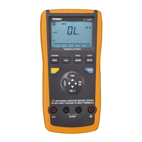
Tenma 72-10465 User manual

Tenma
Tenma 72-7222 User manual

Tenma
Tenma 72-1025 User manual

Tenma
Tenma 72-8150 User manual

Tenma
Tenma 72-14440 User manual

Tenma
Tenma 72-14415 User manual

Tenma
Tenma TEN01073 User manual

Tenma
Tenma 72-8170 User manual

Tenma
Tenma 72-7222 User manual

Tenma
Tenma ST-95 User manual

Tenma
Tenma 72-3515 User manual

Tenma
Tenma 72-7935 User manual

Tenma
Tenma Smart Tweezer ST-5S-BT2 User manual

Tenma
Tenma 72-7228 User manual

Tenma
Tenma 72-7224 User manual

Tenma
Tenma ST-91 User manual