TERASAKI TemPower2 AR-E Series User manual

KRB-5368c
INSTRUCTION MANUAL FOR
AR-E AIR CIRCUIT BREAKERS
(Fixed type and Type AGR-12B Overcurrent Protective Device)
Types: AR206E
AR208E
AR210E
AR212E
AR216E
Notice
Be sure to read this manual before installing, operating, servicing, or inspecting the ACB.
Please retain this manual for future reference.
Electrical work must be done by competent persons.
ACB maintenance, inspection, parts replacement, OCR field tests and setting changes must be performed by competent
persons.


KRB-5368c
-3-
1. SAFETY NOTICES 5
2. RECEIVING AND HANDLING 7
2-1. Transportation Precautions 7
2-1-1. Transporting the ACB 7
2-2. Storage Precautions 8
2-3. Installation Precautions 8
3. GENERAL 10
3-1. Types and Descriptions 10
3-2. Parts and Functions 12
3-3. Circuits and Ratings 15
4. OPERATION 19
4-1. Charging and Opening operation 19
4-1-1. Charging operation 19
4-1-2. Closing operation 20
4-1-3. Opening operation 20
4-1-4. Motion of trip indication and spring charge
indication switches 20
4-1-5. Motion of operation mechanisms 21
4-2. ON-OFF Button Cover Locking Procedure 23
4-3. Lock in OFF Procedure 23
4-4. OCR Cover Locking Procedure 24
5. OVERCURRENT RELEASE (OCR) 24
5-1. Specifications 24
5-2. Characteristics 25
5-2-1. L characteristic for general feeder 25
5-3. OCR Setting Procedure 27
5-4. Operation Indication 28
6. MAINTENANCE, INSPECTION AND PARTS
REPLACEMENT 29
6-1. Inspection Procedures 30
6-2. Parts Replacement Procedure 33
6-2-1. Preparation 33
6-2-2. Arc chambers 36
6-2-3 Latch release coil (LRC) 37
6-2-4. Instantaneously-rated shunt trip device (SHT) 38
6-2-5. Control relay 39
6-2-6. Magnet hold trigger (MHT) 41
6-2-7. Auxiliary switches 42
7. TROUBLESHOOTING FLOWCHARTS 43
TABLE OF CONTENTS

KRB-5368c
-4-

KRB-5368c
-5-
1. SAFETY NOTICES
Thank you for purchasing the TERASAKI AR-series Air Circuit Breaker (TemPower2).
This chapter contains important safety information.
Be sure to carefully read these safety notices, instruction in this manual, and other documents accompanying the Air Circuit Breaker
(hereinafter referred to as the ACB) to familiarize yourself with safe and correct procedures or practices before installing, operating,
or servicing the ACB.
In this manual, safety notices are divided into “DANGER” and “CAUTION” according to the hazard level:
DANGER : A danger notice with this symbol indicates a potentially hazardous situation which, if not avoided, could result in
death or serious injury.
CAUTION : A caution notice with this symbol indicates a potentially hazardous situation which, if not avoided, may result in
minor or moderate injury and/or property damage.
Note that failure to observe a caution notice could result in serious injury/damage in some situations. Because safety notices contain
important information, be sure to read and observe them.
Transportation Precaution
DANGER
Never stand under the ACB that has been lifted or suspended by the lifting attachments. The weight of the ACB may cause
serious injury.
Installation Precautions
CAUTION
Electrical work must be done by competent persons.
Do not place the ACB in such an area that is subject to high temperatures, high humidity, dusty air, corrosive gases, strong
vibration and shock, or other unusual conditions. Mounting the ACB in such an area could cause a fire or malfunction.
Be careful to prevent foreign objects (such as debris, concrete powder, dust, chippings, and iron powder) and oil or rainwater
from entering the ACB. These materials inside the ACB could cause a fire or malfunction.
Prior to commencing any work on the ACB, open an upstream circuit breaker or the like to isolate all sources of
power/voltage. Otherwise, electric shock may result.
Fix the ACB firmly on a flat, level surface using mounting screws. Otherwise, the ACB may cause to fall, resulting in damage
to the ACB or personal injury.
When terminating conductors to the ACB, tighten terminal screws to the torque specified in this manual. Otherwise, a fire
could result.
For 4-pole ACBs, be sure to connect a 3-phase, 4-wire neutral conductor to the N-phase pole (on the right end). Otherwise, an
overcurrent may hinder the ACB from tripping, resulting in a fire.
Operation Precautions
DANGER
Never touch live terminal parts. Doing so will result in electric shock.
CAUTION
Do not force down the charging handle after completion of manual charging operation. Doing so may cause a malfunction.
The permissible operating vol
tage of the spring charging motor is 85 to 110% of the rated ac voltage or 75 to 110% of the rated
dc voltage. Be sure to supply a voltage within the above ranges to the motor. Otherwise, a malfunction, burnout, or fire may
result.

KRB-5368c
-6-
Operation Precautions (continued)
CAUTION
Repeated open/close operation by the motor charging mechanism without pause should not exceed 15 times. If repeated
continuous open/close operation is inevitable, a pause of at least 20 minutes should be provided after the repetitions of 15
times. Otherwise, a spring charging motor may be burnt out.
Do not bring your hand or face close to arc gas vent of the arc chamber while the ACB is closed. Otherwise, a burn may result
from high-temperature arc gas blowing out of the arc gas vent when the ACB trips open.
If the ACB trips open automatically, remove the cause of tripping operation before re-closing the ACB. Otherwise, a fire
could result.
OCR (Overcurrent Release) Handling Precautions
CAUTION
OCR setting changes must be performed by competent persons.
After setting changes are made, the settings be checked with e.g., a type ANS2S OCR test interface unit (optional).
After completion of OCR tests, be sure to return the settings to the original values. Failure to do so may cause a fire or
burnout.
Before changing OCR settings, open the ACB and then lock the OFF button to prevent the ACB from being closed
inadvertently.
Use a small flatblade screwdriver with a torque of not more than 0.1 N·m or a force of not more than 0.1 N when adjusting the
setting switches (rotary step switches or slide switches). An excessive torque or force may cause a malfunction.
Maintenance and Inspection Precautions
CAUTION
ACB maintenance, inspection and parts replacement must be performed by competent persons.
Do not touch ACB current carrying parts and ACB structural parts close to a current carrying part immediately after the ACB
trips open. Remaining heat may cause a burn.
Prior to commencing any work on the ACB, open an upstream circuit breaker or the like to isolate all sources of
power/voltage from the main and control circuits. Otherwise, electric shock may result..
Prior to commencing maintenance, inspection, or parts replacement, make sure that the closing springs are released and the
ACB is open. Otherwise, unintentional open/close operation may lead to fingers or tools to be pinched by the open/close
mechanism, resulting in injury.
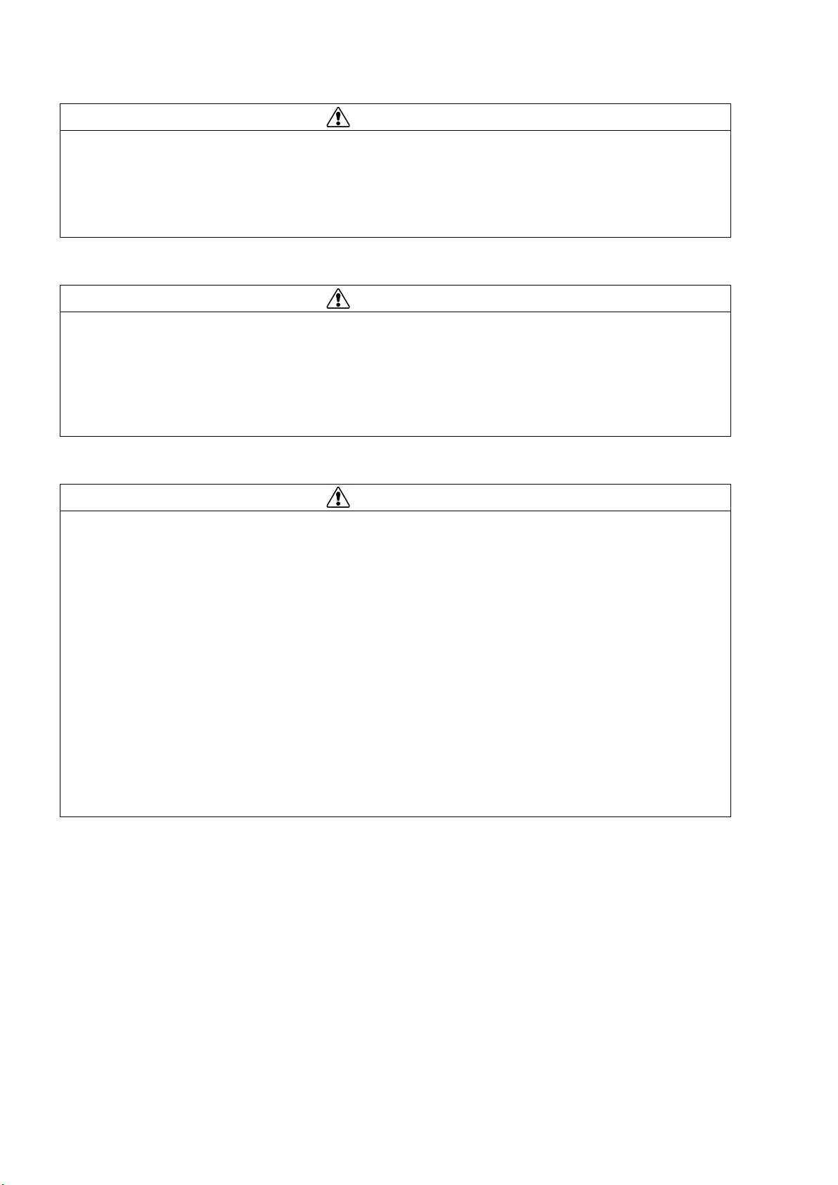
Retighten the terminal screws periodically to the specified torque. Otherwise, a fire could result.
When grinding a contact tip, be careful to prevent grinding dust from entering the breaker operating mechanism. Wipe the tip
clean after grinding. Otherwise, a malfunction or fire could result.
Do not perform dielectric withstand tests under other conditions than specified. Doing so may cause a malfunction.
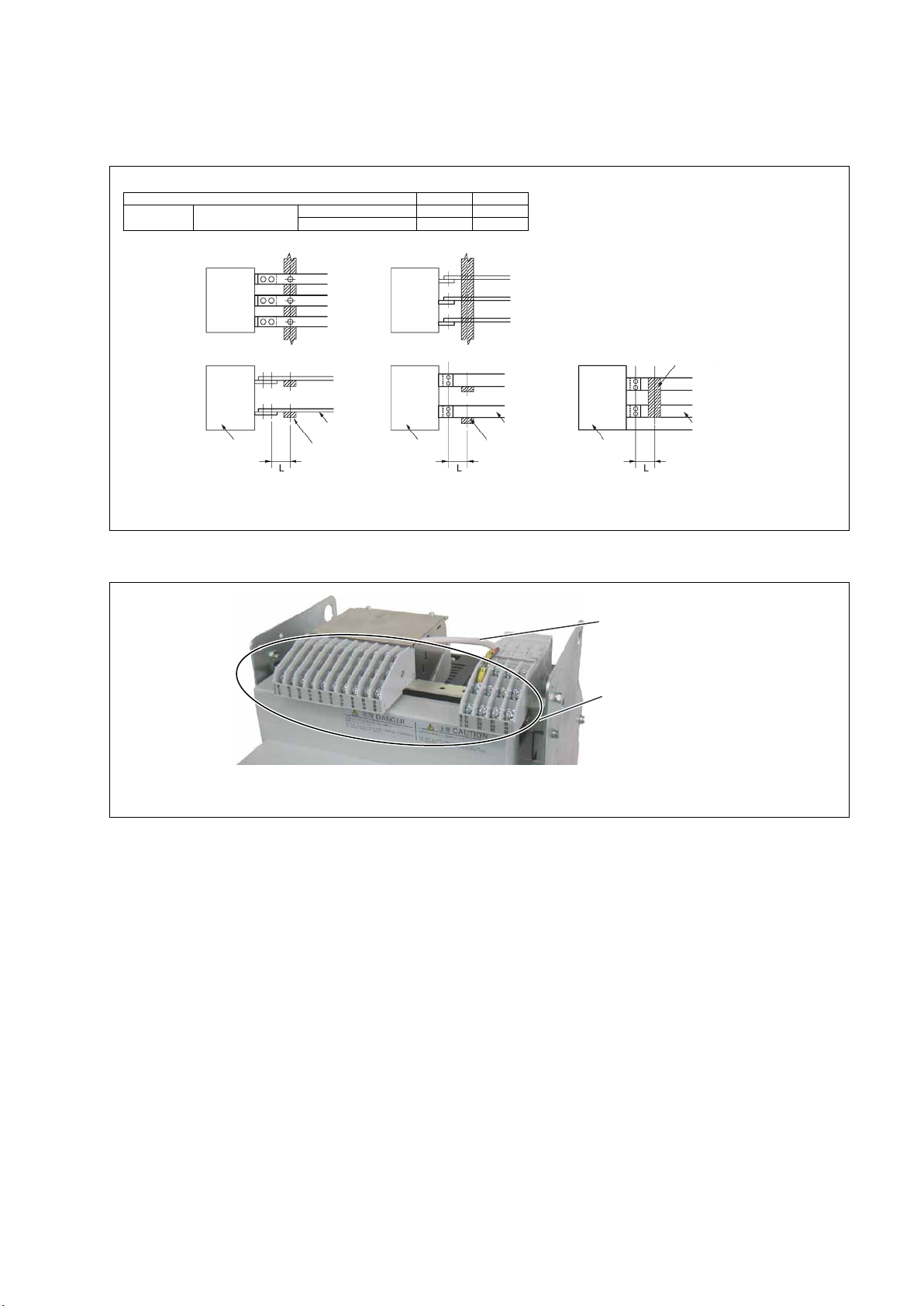
Be sure to reinstall the arc chamber if removed. Failure to do so or incorrect installation of the arc chamber may result in a fire
or burn.
When charging the closing springs or performing open/close operation of the ACB with the arc chamber, front cover and/or
side covers removed during maintenance or inspection work, do not touch parts other than those required for the above
operation (charging handle, ON/OFF buttons, moving core and the like). Doing so may cause fingers or tools to be pinched,
resulting in injury.
When replacing an auxiliary, do not damage the control wire for the auxiliary or pinch the wire between the auxiliary and the
breaker body. Doing so may cause a malfunction.

KRB-5368c
-7-
2. RECEIVING AND HANDLING
Upon receipt of your ACB, check the following. If you have any question or problem, contact us at the indicated on the back cover of
this manual.
Check that the ACB received is as ordered and that the accessories are as specified.
Check that the ACB is not damaged during shipment.
2-1. Transportation Precautions
DANGER
Never stand under the ACB that has been lifted or suspended by a lifting attachments. If the ACB body is accidentally
dropped, its weight may cause serious injury.
2-1-1. Transporting the ACB
When lifting the ACB, hold it using lifting attachments or wire ropes through the lifting holes. Take care that the control circuit
terminals, auxiliary switches, arc gas barrier and control terminal block cover which are shown in Fig. 1 are not damaged by the
lifting rope. Lift the ACB carefully and gently. For transportation, place the ACB on a pallet and carry slowly and carefully.
Avoid shock and vibration to the ACB during transportation.
Do not lay the ACB during transportation.
When transporting the ACB over great distances, crate it for protection against shock and vibration and secure the crate package
with wood or ropes.
Lower the ACB onto a flat, level surface.
Fig. 1 Transporting the ACB
Breaker body
Lifting hole (ø20mm)
Control circuit terminals
Auxiliary switches

KRB-5368c
-8-
2-2. Storage Precautions
It is recommended that the ACB be used as soon as you have received it. If it is necessary to store the ACB, note the following:
Store the ACB in a dry indoor location to prevent condensation due to sudden changes in ambient temperature. Condensation has
a harmful effect on the ACB insulation.
Store the ACB in a clean place free of corrosive gases and dust. In particular, exposure to a mixture of moisture and cement dust
may cause corrosion damage to metal parts of the ACB.
Place the ACB on a flat, level surface in its normal position (Do not lay the ACB).
Do not place the ACB directly on the floor. Do not stack the ACBs during storage.
2-3. Installation Precautions
CAUTION
Electrical work must be done by competent persons.
Do not place the ACB in such an area that is subject to high temperatures, high humidity, dusty air, corrosive gases, strong
vibration and shock, or other unusual conditions. Mounting the ACB in such an area could cause a fire or malfunction.
Be careful to prevent foreign objects (such as debris, concrete powder, dust, chippings, and iron powder) and oil or rainwater
from entering the ACB. These materials inside the ACB could cause a fire or malfunction.
Prior to commencing any work on the ACB, open an upstream circuit breaker or the like to isolate all sources of
power/voltage. Otherwise, electric shock may result.
When terminating conductors to the ACB, tighten terminal screws to the torque specified in this manual. Otherwise, a fire
could result.
For 4-pole ACBs, be sure to connect a 3-phase, 4-wire neutral conductor to the N-phase pole (on the right end). Otherwise, an
overcurrent may hinder the ACB from tripping, resulting in a fire.
Do not install the ACB in such an area that is exposed to direct sunlight.
Make sure that the mounting base has a sufficient capacity of bearing the weight of the ACB (see Table 3). The mounting base
must be protected against vibration. Take appropriate measures to provide a perfect protection to the mounting base against
resonance. Otherwise, open/close operation of the ACB may cause a malfunction of other devices in the switchboard or vibrations
of the switchboard may cause a malfunction of the ACB.
Use the following screws with appropriate length for the main circuit terminals.
Main circuit terminal screws: Hex head M10, with flat washers (2), spring washer (1) and nut (1) per screw
Tightening torque: 22.5 - 37.2 N·m
Table 1 Number of main circuit terminal screws required
ACB type
AR206E - AR216E
Number of main circuit terminal screws (3/4-pole) Vertical , Horizontal, Front terminals 12/16
Use the following screw for the ground terminal. The screw must have a length that allows it to be inserted 4 - 9 mm into the
ground terminal M8 tapped hole.
Ground terminal screw: M8 (1) with spring washer and flat washer
Tightening torque: 11.8 - 14.7 N·m

KRB-5368c
-9-
ACB
Support
Conductor
ACB
Support
Conductor
ACB
Conductor
Support
Horizontal terminals
Vertical terminals
Vertical terminals
Use a support to hold conductors securely at distance L as shown in Fig. 2 and Table 2. Such a support will help preventing the
conductors and main circuit terminals from being deformed or damaged due to a large electromagnetic force caused by any fault
current.
Table 2 The maximum distance of the connection point of ACB to the first conductor support
Short-circuit current (kA) 30 50
L (mm) AR206E - AR216E Horizontal terminals 200 150
Vertical terminals 150 100
Fig. 2 Support mounting
Tighten the terminal screw of control circuit terminals and auxiliary switches according to the Fig.3 torque.
Fig. 3 Control terminal screw, Auxiliary switch terminal
If any work is done near the ACB that have been installed, protect the openings of the ACB with appropriate covers to prevent
spatters, metal chips, wire cuttings or other foreign objects from entering the ACB.
Wire for anti-burnout switch of
instantaneously-rated Instantaneously-
rated shunt trip device
Auxiliary switch terminal screw
(Control terminal screw)
Pan head M4 x 8,
with spring washer and terminal washer
Tightening torque: 1.3 - 1.7 N·m

KRB-5368c
-10-
3. GENERAL
3-1. Types and Descriptions
TemPower2is available in types shown in Tables 3.
Table 3 Ratings
Frame size (A) 630 800 1000 1250 1600
Type
AR206E
AR208E
AR210E
AR212E
AR216E
Max. rated current [I
n
] (A)
*1, *2 JIS,IEC,EN,AS *5 630 800 1000 1250 1600
N-phase rated current (A)
630
800
1000
1250
1600
Number of poles *3, *4
3
4
3
4
3
4
3
4
3
4
Dielectric withstand voltage [Ui] (50/60Hz)
1000
1000
1000
1000
1000
Operating voltage [Ue] (50/60Hz)
690
690
690
690
690
Rated breaking/making current [kA sym rms/kA peak]
JIS,IEC,EN,AS [ICS = ICU] AC690V *6 30/63
AC440V
50/105
JEC
AC550V
30/63
AC460V
50/105
AC220V
Rated short-time current [ICW] [kA rms]
0.5 sec
50
1 sec
42
Rated latching current (kA)
42
Endurance
in number of ON-OFF
cycles *7
Mechanical
With maintenance
20000
Without maintenance
10000
Electrical
Without
mainte-
nance
AC460V
10000
5000
AC690V 7000 3500
Installation
Fixed type
Mass (kg)
35
42
35
42
35
42
38
45
38
45
External dimensions (mm)
Fixedtype
*2
a
356
441
356
441
356
441
356
441
356
441
b
460
c
272
d
63
Connection method Line side Vertical, horizontal or front terminals
Load side
Vertical, horizontal or front terminals
Control circuit terminal type
screw terminals
Spring charging method
Manual or motor charging
Overcurrent release (OCR)
No OCR, or L-characteristic for general feeder protection
Operation indication
Group indication
Tripping device
Tripping coil
(MHT)
Standard equipment for OCR-equipped ACB
Instantaneously-rated
Instantaneously-rated shunt trip
device (SHT)
Optional
undervoltage trip device (UVT)
Optional
Auxiliary switches
Number of switches
4C (standard), 7C or 10C; available for general feeder or microload
Terminal type
screw terminals
Rated voltage Operation power AC100V, A C 11 0 V, AC120V, AC200V, AC220V, AC240V
DC24V, DC48V, DC100V, DC110V, DC125V, DC200V or DC220V
*1: Ambient temperature: 40°C
*2: For both horizontal terminals
*3: For 2-pole applications, use two poles at both ends.
*4: 4-pole ACBs are not applicable to power distribution IT systems unless N-phase protection is provided.
*5: Comply with JIS C 8201-2-1 Ann.1 Ann.2
*6: Protection can not apply IT earthing system.
*7: Expected service life based on endurance test. The service life of ACB depends on the working and environmental conditions. Refer to chapter 6 “Maintenance, Inspection and
Parts Replacement”.
Use the ACBs in the environmental conditions specified in Table 4.
Table 4 Operating environment
Standard
environment
(Standard equipped
ACBs)
Altitude
2000 m max.
Ambient temperature
-5°C to +45°C
Humidity
45 to 85% rel. max.
Vibration
0.7G max.
Shock
200 m/s2(20G) max.
Atmosphere
No excessive water vapor, oil vapor, dust, or corrosive gases. No sudden change in temperature and no condensation.
Ammonia (NH3): 0.5 ppm max, Hydrogen sulfide (H2S)/sulfur dioxide (SO2)/hydrogen chloride (HCl): 0.1 ppm max.,
Chlorine (Cl2): 0.05 ppm max.
Special
environment
(Optional)
Tropical environment
package
Different from standard ACBs in that Ambient temperature: 60°C max. and Humidity: 95% rel. max. (no condensation)
Cold environment
package Different from standard ACBs in that Ambient temperature: -25°C min. for use and -40°C min. for storage (no condensation)
Corrosion-resistant
package Different from standard ACBs in that NH3: 50 ppm max, H2S: 10 ppm max., SO2/HCl: 5 ppm max., and Cl2: 1 ppm max.

KRB-5368c
-11-
Table 5 shows the dielectric withstand voltage and the insulation resistance of the ACBs.
CAUTION
Do not perform dielectric withstand/insulation resistance tests under other conditions than specified. Doing so may cause a
malfunction.
Table 5 Dielectric withstand voltage and insulation resistance
Circuit Dielectric withstand voltage (50/60Hz) Impulse withstand
voltage Uimp
Insulation
resistance
(DC500V Megger
used)
Main circuit Between poles, and terminal group and ground AC3500V 1 minute 12kV
300M
Ω
Control circuit
Auxiliary
switches
For general feeder
Between terminal group and ground
AC2500V
1 minute
6kV
100M
Ω
For microload
Between terminal group and ground
AC2000V
1 minute
4kV
100MΩ
Overcurrent release Between terminal group and ground AC2000V 1 minute 4kV 100MΩ
Undervoltage trip device Between terminal group and ground AC2500V 1 minute 6kV 100MΩ
Other accessories
Between terminal group and ground
AC2000V
1 minute
4kV
100M
Ω
The above data applies to new ACBs. Device terminals within ACBs are not covered. Use a DC500V Megger to measure the insulation resistance.
Table 6 shows the internal resistance and power consumption of the ACBs.
Table 6 Internal resistance and power consumption
Type
AR206E
AR208E
AR210E
AR212E
AR216E
Frame size (A) 630 800 1000 1250 1600
DC internal resistance (mΩ) (for 1-pole ACB) 0.027 0.027 0.027 0.024 0.024
AC power consumption (W) (for 3-pole ACB)
45
75
120
175
260
Table 7 shows applicable current of the ACBs. The applicable current varies depending on the ambient temperatures.
Table 7 Dependence of applicable current on ambient temperature
Type
AR206E
AR208E
AR210E
AR212E
AR216E
Standard
Conductor size
Ambient
temperature (°C)
2×40×5t 2×50×5t 2×60×5t 2×80×5t 2×100×5t
IEC60947-2
EN60947-2
AS3947-2
JISC8201-2-1
40 (standard ambient
temperature) 630 800 1000 1250 1600
45
630
800
1000
1250
1530
50
630
800
1000
1250
1470
55
630
800
1000
1250
1400
60
630
800
970
1210
1330
Notes: Values with horizontal terminals.
Above figures are subject to the design of the enclosure and rating of conductor.

KRB-5368c
-12-
3-2. Parts and Functions
Fig. 4 provides a general views of the ACB.
◯
1ACB
◯
1ACB
◯
1ACB
Fig. 4 General view and parts designation
OFF button ◯
2
ON-OFF button cover ◯
8
Lock-in-OFF plate
◯
7
◯3ON button
◯
8ON-OFF button cover
ON-OFF indicator ◯
4
◯
5Charge indicator
◯
6Charging handle
ON-OFF cycle counter ◯
9
Overcurrent release (OCR)
◯
11
OCR cover ◯
10
Front cover ◯
12
◯
13 Rating nameplate
◯
20 Lifting hole (ø20mm)
◯
18 Ground terminal M8 tapped hole
◯
19 Main circuit terminalControl circuit terminal ◯
15
Auxiliary switches ◯
16
Terminal block ◯
17
Specification
nameplate ◯
14

KRB-5368c
-13-
◯
1
ACB ACB body
◯
2
OFF button Push to open the ACB.
◯
3ON button Push to close the ACB.
◯
4ON-OFF indicator Shows “OFF” when the ACB is open and “ON” when it is closed.
◯
5Charge indicator
Shows “CHARGED” when the closing springs are charged and “DISCHARGED” when it
is released.
◯
6
Charging handle Pump to charge the closing springs.
◯
7Lock-in-OFF plate
Padlocking this plate allows the ACB to be locked in the open (OFF) state. (Padlocks are
not supplied. Use padlocks with a 6 mm-diameter shackle.)
◯
8ON-OFF button cover
Provides protection against inadvertent button operation and can be padlocked. (Padlocks
are not supplied. Use padlocks with a 6 mm-diameter shackle.) Up to three padlocks can be
installed.
◯
9
ON-OFF cycle
counter (optional)
Reads the number of ON-OFF cycles. It counts a series of operations from close to open as
one cycle.
◯
10 OCR cover
Padlocking this plate prevents settings of overcurrent release
◯
11
to be inadvertently
changed. (Padlocks are not supplied. Use padlocks with a 6 mm-diameter shackle.)
◯
11 Overcurrent release
(OCR) (optional)
This protective device is supplied power via the CT for overcurrent installed in the ACB
main circuit. When the CT detects an overcurrent in the main circuit, the OCR instructs the
magnet hold trigger (MHT) to trip open the ACB.
◯
12
Front cover A plastic cover of the breaker body front panel.
◯
13 Rating nameplate Indicates the type, applicable standards and rated breaking capacity of the ACB.
◯
14
Specification
nameplate
Indicates the number of poles, operation method, accessories, and serial number of the
ACB.
◯
15
Control circuit
terminals
Allow connections of external control wire to the control circuits. Wire connections are
made through M4 screw terminals. Fig. 5 shows the control circuit terminals.
Fig. 5 Control circuit terminals
◯
16 Auxiliary switches
(optional)
Indicate the state of the ACB (ON or OFF). The auxiliary switches are available in 4C
configuration (standard), or 7C or 10C configuration (optional). Connections to the
switches are made through M4 screw terminals.
◯
17
Terminal block
Contains control circuit terminals
◯
15
, and auxiliary switches.
◯
16
◯
18
Ground terminal M8
tapped hole
Allows connection of a ground terminal.
◯
19 Main circuit terminals
Allow connections of external conductors. These terminals are available in three
configurations as shown in Fig. 6.

KRB-5368c
-14-
Vertical terminals Horizontal terminals Front terminals
Fig. 6 Main circuit terminals
◯
20
Lifting hole (ø20mm)
Allows lifting attachments or wire ropes to be used for lifting the ACB.

KRB-5368c
-15-
3-3. Circuits and Ratings
Fig. 7 shows an ACB circuit diagram and Table 8 and Fig. 8 show the function of each terminal and the meaning of each sign in the
diagram.
Fig. 7-1 Breaker circuits 1
Table 8-1 Terminal functions and circuit symbols 1 (Applicable to both 50 and 60Hz for AC. and mean the polarity for
DC)
Terminal No.
Function
□
02 , □
22
AC100 - 120V, AC200 - 240V, DC100 - 125V, DC200 - 250V, DC24V or DC48V (To
be stated when ordering)
Operation power input terminals
□
03
,
□
12
ON switch Operation switch terminals
□
05
,
□
15
Group indication
Operation indication contact output
terminals
□
05 , □
17 Trip indication
□
05 , □
27 Spring charged indication
□
10 , □
20 AC100V, AC110V, AC120V, AC200V, AC220V, AC240V, DC24V, DC48V, DC100V,
DC110V, DC125V, DC200V or DC220V (To be stated when ordering)
Instantaneously-rated shunt trip
device power input terminals
□
08 , □
09 , □
18 , □
28
AC100V, AC200V or AC400V unit (To be stated when ordering)
Connect the unit to the applicable terminal Nos.
Undervoltage trip device power
input terminals
Terminal No.
AC100V unit
AC200V unit
AC400V unit
□
08 , □
09 AC100V AC200V AC380V
□
18 , □
09 AC110V AC220V AC415V
□
28 , □
09 AC120V AC240V AC440V
□
24
,
□
30
OFF switch Undervoltage trip
□
19
,
□
29
Polarity: □
19 - , □
29
-
N-phase CT connection terminals *3
□
01 □
04 □
06 □
07 □
11 □
13 □
14
□
16 □
21 □
23 □
25 □
26 — (Reserved)

KRB-5368c
-16-
Fig. 7-2 Breaker circuits 2
Table 8-2 Terminal functions and circuit symbols 2
Symbol
Meaning
Symbol
Meaning
CT1– CT4CT for OCR *6 SHT
Instantaneously rated Instantaneously-
rated shunt trip device *5
MHT
Magnet hold trigger
UVT
Undervoltage trip device
M
Spring charging motor
Hand connector
Ry
Control relay
User wiring
LRC
Latch release coil
Relay or LED
*1: For 4-pole ACBs.
*2: For 4-pole ACBs equipped with N-phase protection and/or ground fault trip functions.
*3: Used for 3-pole ACBs with ground fault trip functions to be installed in a 3-phase, 4-wire circuit.
*4: Do not connect the ON switch with auxiliary switch b-contact in series. Doing so may cause pumping.
*5: To be connected to auxiliary switch terminals □
111 and □
114 to prevent burnout.
*6: Conversion ratio: CT rated primary current In(A)/100mA
111
3rd character: Type of contact
1: Common, 2: b-contact, 4: a-contact
2nd character: Type of switch
1: Auxiliary switch,
1st character: Number of contact
1 - 0:Number of auxiliary
A – C: Number of auxiliary switch for microload
Fig. 8 Terminal number and function of auxiliary

KRB-5368c
-17-
Fig. 9 provides the terminal arrangement of the ACB.
Fig. 9 Terminal arrangement
Tables 9 - 14 show the ratings of the operation power supply, the Instantaneously-rated shunt trip device (SHT), the undervoltage trip
device (UVT), auxiliary switches, operation indication contacts, and the N-phase CT.
Table 9 Ratings of operation power supply
Rated voltage
(V)
Permissible
charging/closing
voltage range
Ratings of operation power supply
Peak motor starting
current (A)
Steady-state motor
current (A)
Peak making current
(A)
Latch release coil
(LRC) resistance
(ohm) *
AC100
85 - 110
7
1.1
0.29
300-380
AC110
94 - 121
7
1.1
0.25
350-440
AC120
102 - 132
7
1.1
0.22
440-540
AC200
170 - 220
4
0.7
0.15
1130-1390
AC220
187 - 242
4
0.7
0.13
1410-1740
AC240
204 - 264
4
0.7
0.11
1710-2090
DC24
18 - 26
14
4
1.04
20-26
DC48
36 - 53
10
1.6
0.51
85-105
DC100
75 - 110
6
0.8
0.25
350-440
DC110
82 - 121
6
0.8
0.22
440-540
DC125
93 - 138
6
0.8
0.21
540-680
DC200
150 - 220
4
0.5
0.13
1410-1740
DC220
165 - 242
4
0.5
0.12
1710-2090
* Ambient temperature: 20°C
Table 10 Ratings of Instantaneously-rated shunt trip device (SHT)
Rated voltage (V) Permissible voltage
range (V)
Peak exciting current
(max.)
(A)
Coil resistance (ohm)
*
Max. contact parting
time (ms)
AC100
70 - 110
1.6
32-40
50
AC110
77 - 121
1.8
32-40
AC120
84 - 132
1.9
32-40
AC200
140 - 220
0.63
135-170
AC220
154 - 242
0.69
135-170
AC240
168 - 264
0.76
135-170
DC24
16.8 - 26.4
2.4
8.9-11
DC48
33.6 – 52.8
1.3
32-40
DC100
70 - 110
0.64
135-170
DC110
77 - 121
0.70
135-170
DC125
87.5 - 137.5
0.80
135-170
DC200
140 - 220
0.33
540-670
DC220
154 - 242
0.36
540-670
* Ambient temperature: 20°C

KRB-5368c
-18-
Table 11 Ratings of undervoltage trip device (UVT)
Rated voltage
(V)
Opening voltage
range (V)
Attraction voltage
(V)
Coil exciting
current (A)
Power consumption (VA)
Coil resistance (ohm) *
Normal
Attraction
AC100
35 - 70
85
0.1 8 10 Holding coil: 410 – 510
Attraction coil: 5.6-6.8
AC110
38.5 - 77
93.5
AC120
42 - 84
102
AC200
70 - 140
170
AC220
77 - 154
187
AC240
84 - 168
204
AC380
133 - 266
323
AC415
145 - 290
352
AC440
154 - 308
374
DC24
8.4-16.8
20.4
DC48
16.8-33.6
40.8
DC100
35-70
85
* Ambient temperature: 20°C
Table 12 Ratings of auxiliary switches
Voltage (V)
Auxiliary switches
For general feeder
For microload
Resistive load (A)
Inductive load (A)
*1
Resistive load (A)
Inductive load (A)
*2
AC100 - 250
5
5
0.1
0.1
AC251 - 500
5
5
-
-
DC30
1
1
0.1
0.1
DC125 - 250
1
1
-
-
*1: AC cosø ≥0.3, DC L/R ≤0.007
*2: AC cosø ≥0.6, DC L/R ≤0.01
*3: Min. applicable load: DC5V/1 mA
Table 13 Ratings of operation indication contacts
Voltage (V)
Rated contact current (A)
Group indication
Spring charging/tripping operation
Resistive load (A)
Inductive load (A) *1
Resistive load (A)
Inductive load (A) *2
AC250
3
3
3
3
DC30
3
3
3
2
DC125
0.5
0.25
0.5
0.5
DC250
0.3
0.15
0.1
0.1
*1: AC cosø ≥0.3, DC L/R ≤0.007
*2: AC cosø ≥0.6, DC L/R ≤0.01
*3: Min. applicable load: DC5V/1 mA
Table 14 Ratings of N-phase CT
Type of ACB Type of N-phase CT Ratings (A)
AR206E T2GB40N06A 630A/100mA
AR208E
T2GB40N08A
800A/100mA
AR210E
T2GBX6N10A
1000A/100mA
AR212E T2GBX6N12A 1250A/100mA
AR216E T2GBX6N16A 1600A/100mA

KRB-5368c
-19-
4. OPERATION
4-1. Charging and Opening operation
DANGER
Never touch live terminal parts. Otherwise, electric shock may result.
CAUTION
Do not force down the charging handle after completion of manual charging operation. Doing so may cause a malfunction.
The permissible operating voltage of the spring charging motor is 85 to 110% of the rated ac voltage or 75 to 110% of the
rated dc voltage. Be sure to supply a voltage within the above ranges to the motor. Otherwise, burnout may result.
Repeated open/close operation by the motor charging mechanism without pause should not exceed 15 times. If repeated
continuous open/close operation is inevitable, a pause of at least 20 minutes should be provided after the repetitions of 15
times. Otherwise, a spring charging motor may be burnt out.
Do not bring your hand or face close to arc gas vent of the arc chamber while the ACB is energized. Otherwise, a burn may
result from high-temperature arc gas blowing out of the arc gas vent when the ACB trips open.
If the ACB trips open automatically, remove the cause of tripping operation before re-closing the ACB. Otherwise, a fire
could result.
The ACBs are available in two types in terms of the closing spring charging method and the remote operation capability: a manual
charging type and a motor charging type. The manual charging type requires the charging and ON-OFF (close/open) operation to be
done manually while the motor charging type allows the operation to be done either manually or by using a motor.
4-1-1. Charging operation
The ACB can be closed only when the closing springs have been charged. Be sure to charge the closing springs before closing the
ACB. The charging operation is permitted, regardless of whether the ACB is ON (closed) or OFF (open). The procedure for charging
the closing springs is as follows:
Manual charging
Pump the charging handle (Fig. 10 ◯
2) until the charge indicator (Fig. 10 ◯
1) shows “CHARGED” Pumping the handle with the full
stroke 6 - 8 times will fully charge the closing springs.
Fig. 10 Charging and opening operation
◯
1Charge indicator
◯
2Charging handle
◯
6ON button
◯
5ON-OFF button cover
ON-OFF indicator ◯
7
OFF button ◯
3
Lock-in-OFF plate ◯
4
ON-OFF button cover

KRB-5368c
-20-
Motor charging
When the charge indicator (Fig. 10 ◯
1) changes to “DISCHARGED” while the specified operation voltage is applied to the control
circuit terminals □
02 and □
22 , the charging motor is activated to start charging the closing springs. Upon completion of the charging
operation, the charge indicator shows “CHARGED” and the charging motor is automatically deactivated. The time required for the
motor charging operation depends on the operation voltage or the ACB types, but does not exceed 10 seconds.
4-1-2. Closing operation
The ACB closing operation is not permitted unless all of the following conditions are met.
1) The charge indicator (Fig. 10 ◯
1) shows "CHARGED".
2) The OFF button (Fig. 10 ◯
3) is not locked with the lock-in-OFF plate (Fig. 10 ◯
4).
3) The specified voltage is supplied to the undervoltage trip device .
Manual closing
Open the ON-OFF button cover (Fig. 10 ◯
5) and press the ON button (Fig. 10 ◯
6) The ACB will be closed with a sound. The ON-
OFF indicator (Fig. 10 ◯
7) shows "ON" and the charge indicator (Fig. 10 ◯
1) shows "DISCHARGED".
Electrical closing
Press the ON switch shown in Fig. 7. The latch release coil (LRC) (Fig. 7) will be excited and the ACB is closed with a sound. The
ON-OFF indicator (Fig. 10 ◯
7) shows "ON", the charge indicator (Fig. 10◯
1) shows "DISCHARGED", and the charging motor starts
charging the closing springs.
4-1-3. Opening operation
Manual opening
Open the ON-OFF button cover (Fig. 10 ◯
5) and press the OFF button (Fig. 10◯
3). The ACB will trip open with a sound. The ON-
OFF indicator (Fig. 10 ◯
7) shows "OFF".
Electrical opening
Press the OFF switch shown in Fig. 7. The Instantaneously-rated shunt trip device (SHT) or the undervoltage trip device (Fig. 7) will
be excited so that the ACB trips open with a sound. The ON-OFF indicator (Fig. 10 ◯
7) shows "OFF".
4-1-4. Motion of trip indication and spring charge indication switches
The trip indication and spring charge indication switches provide the breaker status as shown in Table 15.
Table 15 Motion of trip indication and spring charge indication switches
Type of OCR Operation
Contact output
Terminal No.
See Fig. 16
State
Closing spring ACB closed ACB open
Charged
Discharged
Not ready to close *
Ready to close *
All
Trip □
05 , □
17 No change No change OFF ON OFF
Spring charge □
05 , □
27 ON OFF No change No change No change
* “Ready to close” means that all of the following conditions are met:
1. The closing springs are charged.
2. Opening operation is complete (At least 40 ms has elapsed after trip signal was produced).
3. The OFF button is released.
4. The specified voltage is applied to the undervoltage trip device (if equipped).
This manual suits for next models
5
Table of contents
Other TERASAKI Circuit Breaker manuals

TERASAKI
TERASAKI TemBreak 2 E125 User manual

TERASAKI
TERASAKI TemBreak PRO T2FP12LS User manual

TERASAKI
TERASAKI TemBreak PRO XDM1 User manual

TERASAKI
TERASAKI TemBreak PRO TPPM12A User manual

TERASAKI
TERASAKI TemPower 2 User manual

TERASAKI
TERASAKI TemBreak 2 User manual

TERASAKI
TERASAKI NHP TemBreak PRO P160 Series User manual

TERASAKI
TERASAKI TemBreak PRO T2MS4 User manual

TERASAKI
TERASAKI TemBreak 2 T2PM12B User manual

TERASAKI
TERASAKI AME Series User manual