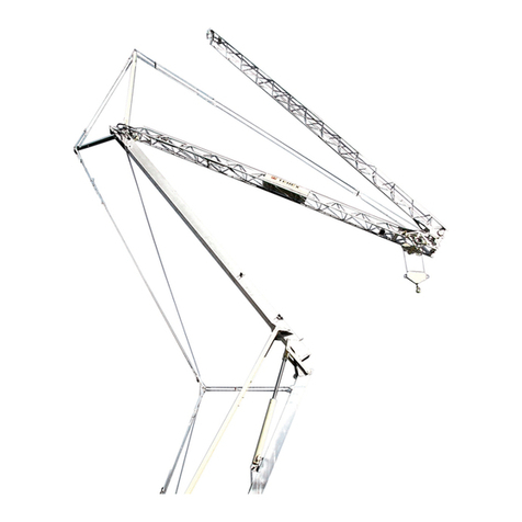
Terex CBR 40H-4 Operating and maintenance manual

Self-Erecting
Tower Crane
CBR 40H– 4
REV.000-1
Operating Instructions - Installation
Maintenance


FOREWORD
CBR page 0.01
rev. 05.05 CBR_0i_01
This publication must be read carefully by the personnel assigned to the crane before taking
any action.
Only by meticulously following the instructions given in this manual will the crane be able
over time to provide the high performance for which it has been designed and constructed.
The manual highlights important information for the safety of persons and conservation of
the machine with the following wording:
WARNING: When failure to observe or incorrect observation of the prescribed instructions
can put the safety of persons at risk and cause mortal accidents.
CAUTION: When failure to observe or incorrect observation of the prescribed instructions
can cause damage to the machine.
NOTICE: This is used to draw attention to particular technical aspects or to refer to other
available information.
The manual is split into 4 sections:
1 MAIN CHARACTERISTICS
2 SITE PREPARATION - TRANSPORT
3 ERECTION - USE - DISMANTLING
4 MAINTENANCE
The Comedil After-Sales Service Organization is at the customer's disposal for any
problems relating to use of the crane and for any necessary advice.
Edition 2010 - Gru Comedil s.r.l.
The content of this manual belongs to exclusively Gru Comedil.
No part of this publication may be duplicated without prior written approval from Gru
Comedil.

TABLE OF CONTENTS
CBR page 0.02
rev. 05.05 CBR_0i_02
TABLE OF CONTENTS
1 MAIN CHARACTERISTICS page
1.1 MARKING 1.01
1.1.1 MANUFACTURER 1.01
1.1.2 TYPE OF MACHINE 1.01
1.1.3 CE MARKING 1.02
1.1.4 NOISE EMISSION MARKING 1.02
1.1.5 IDENTIFICATION PLATE 1.03
1.2 FOREWORD 1.04
1.2.1 SCOPE AND LIMITS OF THE MANUAL 1.04
1.2.2 WHERE AND HOW TO CONSERVE THE MANUAL 1.04
1.2.3 SUPPLEMENTS AND UPDATES TO THE MANUAL 1.05
1.2.4 USER COOPERATION 1.05
1.2.5 EXCLUSION OF RESPONSIBILITY 1.05
1.3 INTENDED CONDITIONS OF USE 1.06
1.3.1 DESCRIPTION OF THE EQUIPMENT 1.06
1.3.2 CLASSIFICATION ACCORDING TO THE CALCULATION STANDARD 1.06
1.3.3 RANGE OF CONTEMPLATED SET-UPS 1.06
1.3.4 OPERATING ENVIRONMENT 1.10
1.3.5 PERMITTED MOVEMENTS AND THEIR SIMULTANEITY 1.10
1.3.6 POSSIBILITY OF INTERFERENCE WITH OTHER EQUIPMENT 1.10
1.3.7 CONTROL STATION 1.10
1.3.8 OPERATIONAL CONTROL 1.11
1.3.9 CONTROL ELEMENTS 1.12
1.3.9.1 PUSHBUTTON PANEL WITH CABLE 1.12
1.3.9.2 MAIN SWITCH 1.12
1.3.10 OPERATING MODE SELECTORS 1.12
1.3.11 STOPPING MOVEMENTS 1.13
1.3.12 CHARACTERISTICS OF PERMISSIBLE LOADS 1.13
1.3.13 PERMISSIBLE HOISTING ACCESSORIES 1.14
1.3.14 DECOMMISSIONING THE CRANE 1.14
1.3.15 POTENTIAL NON-PERMISSIBLE USES OF THE CRANES 1.15
1.4 TECHNICAL DESCRIPTION 1.19
1.4.1 MAIN COMPONENTS 1.19
1.4.2 DESCRIPTION OF THE STRUCTURES 1.20
1.4.3 LOAD-HANDLING DEVICE 1.20
1.4.4 CHARACTERISTICS OF THE ROPES 1.20
1.4.4.1 DIAGRAM OF THE ROPES 1.21

TABLE OF CONTENTS
CBR 40H page 0.03
rev. 12.05 40H_0i_03
1.4.5 MECHANISMS 1.22
1.4.5.1 HOISTING 1.22
1.4.5.2 TROLLEY TRAVERSING 1.23
1.4.5.3 SLEWING 1.23
1.4.5.4 ERECTION 1.24
1.4.6 HYDRAULIC DIAGRAM 1.25
1.4.7 PRECAUTIONS WHEN USING THE HYDRAULIC SYSTEM 1.26
1.4.8 CONTROL MEMBERS 1.27
1.4.8.1 MAIN SWITCH 1.27
1.4.8.2 PUSHBUTTON PANEL 1.28
1.4.9 COUNTERWEIGHT BALLAST 1.29
1.4.9.1 COMPLETION BLOCKS 1.30
2 SITE PREPARATION AND TRANSPORT
2.1 SITE PREPARATION 2.01
2.1.1 ERECTION CLEARANCES 2.01
2.1.2 SUPPORTING BASE 2.01
2.1.3 ELECTRICAL CONNECTION 2.02 2.1.4
PROTECTION FROM ELECTRIC DISCHARGE 2.03
2.1.5 GROUNDING SYSTEM 2.03
2.1.6 COUNTERWEIGHT BALLAST 2.04
2.1.7 TOWING VEHICLES 2.04
2.1.8 TEST LOADS 2.04
2.1.9 SLEWING AREA FENCING 2.04
2.1.10 SAFETY SIGNS 2.05
2.2 INSTRUCTIONS FOR TOWING AND TRANSPORT 2.06
2.2.1 CONDITIONS OF TOWING 2.06
2.2.2 TOWING SET-UP 2.06
2.2.3 DETACHED PARTS 2.07
2.2.4 PERMISSIBLE LOADS ON THE AXLES AND DRAWBAR 2.07
2.2.5 TYRES 2.07
2.2.6 SPECIAL INSTRUCTIONS 2.08
2.2.7 TOWING OPERATIONS NOT PERMITTED 2.08
2.2.8 TRANSPORT 2.09
2.3 STRUCTURES AND METHODS OF ACCESS 2.10

TABLE OF CONTENTS
CBR 40H page 0.04
rev. 12.05 40H_0i_04
3 ERECTION - USE - DISMANTLING page
3.1 INSTRUCTIONS FOR POSITIONING AND ERECTION 3.01
3.1.1 ELECTRICAL CONNECTION 3.01
3.1.2 POSITIONING THE CRANE 3.04
3.1.3 PREPARING THE JIB 3.06
3.1.4 TOWER ERECTION 3.07
3.1.5 BALLASTING 3.08
3.1.6 JIB ALIGNMENT 3.10
3.2 SAFETY DEVICES - FUNCTION AND SETTING 3.13
3.2.1 POSITIONING THE SAFETY DEVICES ON THE CRANE 3.14
3.2.2 STATIC MOMENT LIMITER 3.15
3.2.3 DYNAMIC MOMENT LIMITER 3.16
3.2.4 HIGH SPEED LIMITER 3.17
3.2.5 MAXIMUM LOAD LIMITER 3.18
3.2.6 UP LIMIT SWITCH 3.19
3.2.7 DOWN LIMIT SWITCH 3.20
3.2.8 TROLLEY LIMIT SWITCH 3.21
3.2.9 SLEWING LIMIT SWITCH 3.22
3.3 BRAKES - TESTING AND SETTING 3.23
3.4 GENERAL OPERATING INSTRUCTIONS 3.25
3.4.1 BEFORE PUTTING INTO SERVICE 3.25
3.4.2 INSTRUCTIONS FOR A RATIONAL USE OF THE CONTROLS 3.25
3.4.3 TAKING OUT OF SERVICE 3.26
3.5 SWITCHING OVER 2/4-PART LINES 3.27
3.6 DISMANTLING INSTRUCTIONS 3.28

TABLE OF CONTENTS
CBR page 0.05
rev. 05.05 CBR_0i_05
4 MAINTENANCE page
4.1 MAINTENANCE INSTRUCTIONS 4.01
4.1.1 GENERAL 4.01
4.1.2 MAINTENANCE SCHEDULE 4.01
4.1.3 SLEWING RING 4.04
4.1.4 TROLLEY ROPE TENSIONING 4.04
4.1.5 CHECKING THE ROPES 4.05
4.1.6 LUBRICATION 4.06
4.1.7 STORING THE CRANE 4.06
4.2 INSTRUCTIONS FOR ROUTINE REPAIRS 4.07
4.2.1 GENERAL TROUBLE OF AN ELECTRICAL NATURE 4.07
4.2.2 ELECTRICAL TROUBLE WITH HOISTING 4.08
4.2.3 ELECTRICAL TROUBLE WITH TROLLEY TRAVERSING 4.09
4.2.4 ELECTRICAL TROUBLE WITH SLEWING 4.09
4.2.5 OPERATIONAL TROUBLE WITH ERECTION 4.09
4.2.6 MISCELLANEOUS OPERATIONAL TROUBLE 4.10
4.3 INSTRUCTIONS FOR REMAINING HAZARDS 4.11
4.3.1 NATURE OF REMAINING HAZARDS: SAFETY MEASURES 4.11
4.4 TRAINING PERSONNEL 4.14
4.5 DEMOLISHING THE EQUIPMENT 4.15


Self-Erecting
Tower Crane
CBR 40H– 4
REV.000-1
- MAIN CHARACTERISTICS
1


1 MAIN CHARACTERISTICS
CBR 40H-4 page 1.01
rev. 05.05 CBR_1i_01
1.1 MARKING
1.1.1 MANUFACTURER
Gru Comedil srl – via delle innovazioni 17– 33074 Fontanafredda (PN) ITALY
Phone +39. 0434 989 111
Fax +39. 0434 565 137
Internet home page: http://www.terexcranes.com
IMPORTER / RESELLER
1.1.2 TYPE OF MACHINE
TOWER CRANE: equipment with discontinuous operation for professional use
intended to hoist off a rigid surface and move through the air an unguided unit
load hanging directly from the hook with the permissible hoisting or slinging
accessories in between.
MODEL....................CBR 40H-4
SERIAL No............................................
YEAR OF MANUFACTURE.............................

1 MAIN CHARACTERISTICS
CBR 40H page 1.02
rev.21.02.07 40H_1i_02
1.1.3 CE MARKING
The crane bears the CE marking for conformity with the Machinery Directive
98/37/EC and subsequent amendments.
The marking is on the data plate on the
door of the electric box
The original signed "EC Declaration of Conformity" is delivered with the crane.
This document is an integral part of the machine; it must be kept with care in
order to be able to be shown at the request of the authorities and to be handed
over to the new owner if the crane is sold.
1.1.4 NOISE EMISSION MARKING
The crane bears the marking for noise emission in the environment in conformity
with Directive 2000/14/EC
The data plate is on the door of the electric
box
The original signed "Certificate of Conformity" is delivered with the crane.
The certificate states the actual value measured on a sample machine; this value
is 90 dB(A).
This document is an integral part of the machine; it must be kept with care in
order to be able to be shown at the request of the authorities and to be handed
over to the new owner if the crane is sold.

1 MAIN CHARACTERISTICS
CBR 40H page 1.03
rev.05.10.07 40H_1i_03
1.1.5 IDENTIFICATION PLATE
The data plate shown below is on the door of the electric box.
It bears the crane's specifications as well as its identification data. The data plate
is an integral part of the machine and must not be removed until the machine is
dismantled.
30000 k
g
30000 k
g

1 MAIN CHARACTERISTICS
CBR page 1.04
rev. 05.05 CBR_1i_04
1.2 FOREWORD
1.2.1 SCOPE AND LIMITS OF THE MANUAL
This manual is mainly intended for the owners of cranes and their site managers
and in general all operators involved in moving, installing, using and servicing the
crane.
The purpose of this manual is to provide information on:
•the intended use of the crane in the project
•the crane's technical characteristics
•site preparation
•towing and travelling
•installation, erection and dismantling
•the safety devices and their settings
•use and maintenance
•training personnel
•final demolition of the crane
•availability of spare parts
This manual can in no way substitute the specific experience of the fitter and
operator. For demanding operations, such as erection, this manual is only an aid
to memory for operators who have specific knowledge of this model.
Comedil disclaims all responsibility deriving from using fitters who do not belong
to its After-Sales Service organization.
Use of the crane is anyhow subordinate to not only the prescriptions of this
manual, but also to observance of all the safety standards required by the current
specific legislation in the nation where the equipment is installed.
The instructions manual is an integral part of the equipment and must be
conserved for future reference until the crane is scrapped.
1.2.2 WHERE AND HOW TO CONSERVE THE MANUAL
The instructions manual must always be available for reference at the site where
the crane operates. It is advisable to entrust it to the care of the site manager who
will keep it in a place well protected from the weather; for this purpose it is
possible to use the inside pocket of the door of the electrical equipment.
In the event of damage that even partially impairs its reference, the user must
acquire a new copy to be requested solely from Comedil.

1 MAIN CHARACTERISTICS
CBR page 1.05
rev. 05.05 CBR_1i_05
1.2.3 SUPPLEMENTS AND UPDATES TO THE MANUAL
This manual represents the state of technology at the time of marketing the crane
to which it refers; it must not be considered inadequate just because it has been
subsequently updated in the light of new experience.
Comedil reserves the right to modify its production and associated manuals
without moreover being bound to update what was previously delivered. Any
supplements to the manual that Comedil may deem fit to send out to users must
be kept together with the manual of which they will be an integral part.
1.2.4 USER COOPERATION
Comedil is at the disposal of its Clientele to provide further information and to
consider proposals to improve the manual.
If the crane is sold, the user is invited to notify Comedil of the address of the new
owner in order to facilitate sending any supplements to this manual.
1.2.5 EXCLUSION OF RESPONSIBILITY
Comedil disclaims all direct and indirect responsibility deriving from:
•improper use of the crane
•use by personnel that have not been trained
•use not in conformity with the current regulations in the country of
installation
•preparation of the site not conforming to the instructions and regulations
•unsuitable characteristics of the ground
•supply defects
•lack of maintenance
•unauthorized modifications or repairs
•use of non-genuine spare parts or ones that are not specific for the crane
model
•total or partial inobservance of the prescriptions contained in the manual
•extraordinary events
NOTICE: Failure to observe the above shall make the contractual warranty conditions
null and void.

1 MAIN CHARACTERISTICS
CBR page 1.06
rev. 05.05 CBR_1i_06
1.3 INTENDED CONDITIONS OF USE
1.3.1 DESCRIPTION OF THE EQUIPMENT
The tower crane described in this manual is a device for hoisting and
transportation intended solely for professional use.
General characteristics:
•slewing: at the bottom
•installation method: in fixed position
•supporting members: 4 stabilizers with screw adjustment
•type of erection: hydraulic self-erecting
•load-handling device: single hook
•mobility: on axles equipped with tyred wheels
NOTICE: The hoisting accessories, the supports to place between the stabilizers and the
ground and any anchorages are not considered as belonging to the crane and therefore are
not mentioned in the manual.
1.3.2 CLASSIFICATION ACCORDING TO THE CALCULATION STANDARD
calculation standard for the structures DIN 15018 pt 1
hoisting class H1
stress group B3 - (B2 for the jib)
maximum number of operating cycles 200.000
stability calculation standard DIN 15019
calculation standard for the ropes DIN 15020 pt 1
standard referring to the electrical parts CEI-EN 60204
classification standard for the mechanisms UNI ISO 4301-3
calculation standard for the effects of the wind DIN 1055 pt 4
1.3.3 RANGE OF CONTEMPLATED SET-UPS
The contemplated working set-ups are illustrated on the following pages with the
main performance and specifications of the crane indicated.

1 MAIN CHARACTERISTICS
CBR 40H page 1.07
rev. 40H_1i_07
25.6 m
1000 k
g
38
.
8
m
1000 k
g
39.5 m
32.2 m
29.1 m
WARNING: When the jib is raised by 10° and 15° it is permissible to use the 2-part line
only.

1 MAIN CHARACTERISTICS
CBR 40H page 1.08
rev. 40H_1i_08
CAPACITY DIAGRAMS
Radius 40 m
2/4-part line
4000 3000 2500 2000 1850 1600 1200 1000
kg
13.0 16.5 19.2 23.0 24.5 27.6 34.7 40
m
raised 10° (2-part line only)
2000 1850 1600 1200 1000
kg
22.7 24.2 27.3 34.3 39.5
m
raised 15° (2-part line only) : 1000 kg constant
Jib folded: radius 27.5 m
2/4-part line
4000 3000 2500 2000 1850
kg
14.5 18.4 21.4 25.8 27.5
m
raised 10° (2-part line only)
2000 1850 kg
25.5 27.2 m
raised 15° (2-part line only): 1000 kg constant

1 MAIN CHARACTERISTICS
CBR 40H page 1.09
rev. 40H_1i_09
movement speed (m/min) capacity (kg) power (kW)
micro 6 2000
2-part line slow 23 2000 8.8
fast 46 1000
HOISTING
micro 3 4000
4-part line slow 11.5 4000 8.8
fast 23 2000
TROLLEY TRAVERSING 16 / 46 4000/2000 3
SLEWING 0.3 - 0.9 rpm 1.1 (6 daNm)
ERECTION 2.2
Necessary electric power at 400 V - 50Hz 20
Ballast 25,680 kg Crane weight 15,400 kg
6.5 m

1 MAIN CHARACTERISTICS
CBR 40H page 1.10
rev. 40H_1i_10
1.3.4 OPERATING ENVIRONMENT
The recommended operating environment is the following:
temperature - 5 to 40 °C
maximum relative humidity 90%
maximum wind speed:
•in operation 72 km/h
•during erection 30 km /h
•out of service 102 km/h on the ground
151 km/h above 20 m in height
1.3.5 PERMITTED MOVEMENTS AND THEIR SIMULTANEITY
The crane has the following working movements:
•Hoisting with three speeds
•Slewing with two speeds
•Trolley traversing with two speeds
CAUTION: The working movements can be performed simultaneously provided they are not
started or stopped at the same time.
1.3.6 POSSIBILITY OF INTERFERENCE WITH OTHER EQUIPMENT ORFIXED
OBSTACLES
Crane installation is not permissible if there are any of the following conditions:
•interference of the revolving part with any fixed or movable obstacle that
may be in the crane's range of action.
•interference between the ropes, hoisting accessories and loads with other
cranes nearby.
•vicinity of an electric power line, if the minimum distance between the
most protruding rotating part of the crane, including the load, and the
nearest cable of the line is 5 m (Italian Presidential Decree DPR No.
164/56 art.11). Contact the electricity company to check the required
safety distance for the power of the line.
1.3.7 CONTROL STATION
The control station must be on the ground or at a point on the construction judged
by the operator to be suitable.
It is not permissible for the operator or anyone else to be in the area covered by
the rotation of the platform that must be made off limits by setting up appropriate
barriers (see point 2.1.9).
Table of contents
Other Terex Construction Equipment manuals

Terex
Terex MHL360 E User manual

Terex
Terex RL4000 User manual

Terex
Terex RT200-1 User manual

Terex
Terex Bid-Well 4800 User manual
Terex
Terex RL4000 User manual
Terex
Terex CRC1150S User manual

Terex
Terex Franna AT-15 User manual

Terex
Terex CBR 24 PLUS User manual

Terex
Terex Genie GTH-5519 User manual

Terex
Terex RL4000 User manual
Terex
Terex HI-RANGER TM Series User manual

Terex
Terex TV800 Manual

Terex
Terex Genie SX-135 XC User manual

Terex
Terex RT700 User manual

Terex
Terex TA9P Tier 4 Final User manual

Terex
Terex HC60 Assembly instructions

Terex
Terex MAC 25 User manual

Terex
Terex T300-1 User manual

Terex
Terex Genie GTH-1544 User manual

Terex
Terex GTH10E-12500 Installation and operating manual