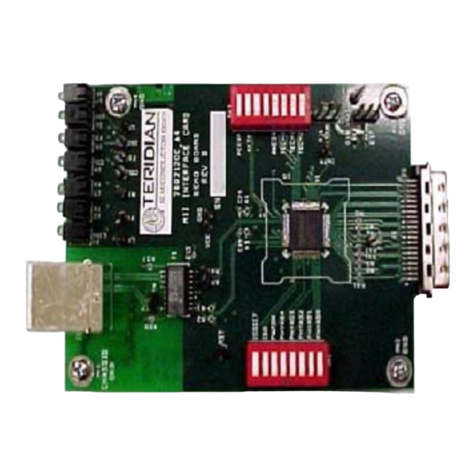
73M1903 MODEM ANALOG FRONT END DEMO BOARD User’s Manual
Revision 1.2 14 of 32
© Copyright 2005 TERIDIAN Semiconductor Corporation
2.3 73M1903 SYSTEM INITIALIZATION
The following example shows the sequence to bring the 73M1903 device out of reset and to start up after
power up.
NOTE: The TERIDIAN73M1903 device does not have an automatic power on reset circuit. After the
power has stabilized, a reset signal should be asserted from the host by pulling the reset pin low for
100ns or longer. The 73M1903 device will be ready to use within 100us after the removal of the reset
pulse from this pin.
RESET 73M1903 Device
1. Power up the system
2. Wait for 3.3V power to be stable
3. Hold RESET pin low for 100ns, then return to high state
4. Wait for 100us for PLL, OSC to be stabilized
Initialing the 73M1903 Device from an unknown state
A. FRAME SYNCHRONIZATION
1. RESET HC bit (Reg01 bit 0) in a frame sequence
2. RESET HC bit (Reg01 bit 0) in next frame sequence
The 73M1903 is guaranteed to be in software-controlled control frame mode. All the MAFE serial data
will be data unless the host requests a control frame by setting bit 0 of data.
B. CONTROL FRAME GENERATION
SOFTWARE CONTROLLED CONTROL FRAME
1. Set TXD Bit 0 to 1 to request a control frame.
2. Write or read the 73M1903 register using the MAFE control data format.
3. Make sure to clear TXD bit 0 to 0 if another control frame is not needed.
HARDWARE CONTROLLED CONTROL FRAME
1. Set TXD Bit 0 to 1 to request a subsequent control frame.
2. SET HC bit (Reg01 bit0) using the MAFE control data format in the next frame.
There will now be alternating data and control frames. It will be necessary to keep track of whether
the 73M1903 is in a data or control frame from this point forward.
Example 1. Using Software controlled control Frame (Note: CTRL_FRAME = 0x0001):
static const U16 init_afe_config[] = // MUST HAVE Data(LSB=1), Control, Data(LSB=1),Control,….
{
CTRL2|0x00, CTRL2|0x00, // Force to Software controlled control frame
CTRL_FRAME, CTRL13|0x00, // Force to Xtal clock
CTRL_FRAME, CTRL1|ENFE, // Enable Analog
CTRL_FRAME, CTRL2|0x00, // Software controlled control frame
CTRL_FRAME, GPIO|0x00,
CTRL_FRAME, GDIR|0xD0, // GPIO 7,6,4=in 5,3,2,1,0=output
CTRL_FRAME, GIE|0x00,
CTRL_FRAME, GIP|0x00,
CTRL_FRAME, BGTRIM|0x00,
CTRL_FRAME, TEST|0x00,
CTRL_FRAME, CTRL08|AFE_CTRL08, // Timing NCO set up
CTRL_FRAME, CTRL09|AFE_CTRL09,
CTRL_FRAME, CTRL10|AFE_CTRL10,
CTRL_FRAME, CTRL11|AFE_CTRL11,
CTRL_FRAME, CTRL12H|AFE_CTRL12H,
CTRL_FRAME, CTRL12L|AFE_CTRL12L,
CTRL_FRAME, RWB|GPIO, // Delay for 2 sample cycle time to
CTRL_FRAME, RWB|GPIO, // let PLL settle before Lockdet


