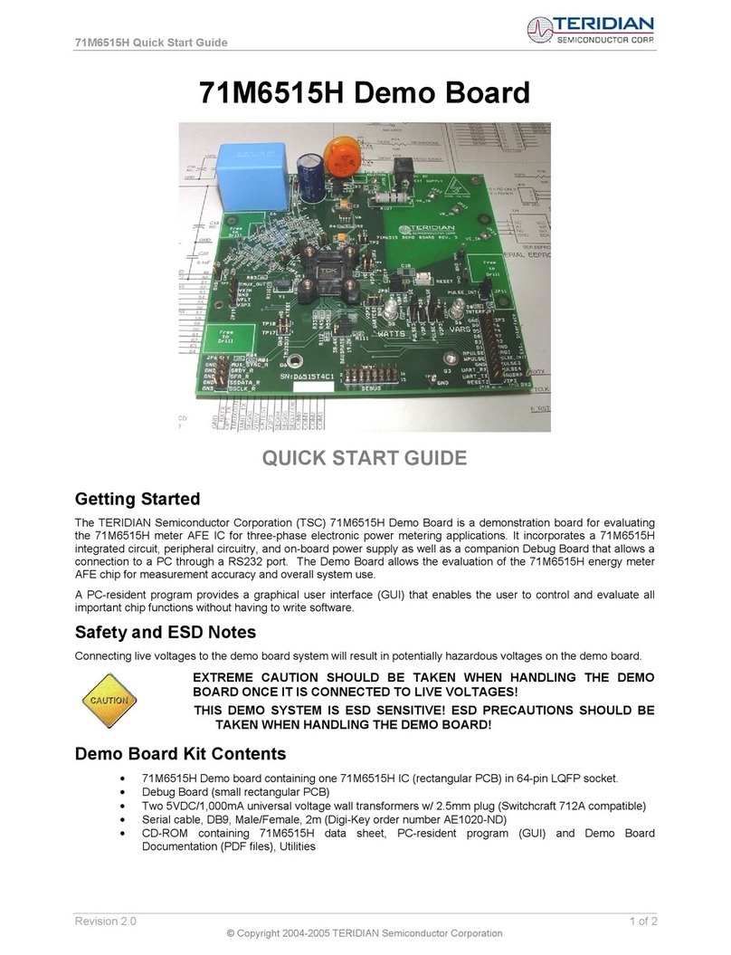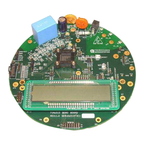
71M6515H Demo Board User’s Manual
3.2.1 JP6 – SSI Interface .................................................................................................................................... 44
3.2.2 JP18 – External Interface........................................................................................................................... 44
3.2.3 JP21 – Debug Interface ............................................................................................................................. 45
3.3 Board Hardware Specifications ..................................................................................................................... 46
4APPENDIX........................................................................................................................................................ 47
List of Figures
Figure 1-1: TERIDIAN 71M6515H Demo and Debug Boards: Basic Connections......................................................... 8
Figure 1-2: Block diagram for the TERIDIAN 71M6515H Demonstration Meter with Debug Board .............................. 9
Figure 1-3: Control Program Icon................................................................................................................................. 10
Figure 1-4: Host GUI Window w/ Functional Groups (Areas) Marked and Numbered ................................................. 12
Figure 2-1: Phase Angle Definitions............................................................................................................................. 28
Figure 2-2: Watt Meter with Gain and Phase Errors ................................................................................................... 28
Figure 2-3: Calibration Spreadsheet for Three Measurements .................................................................................... 32
Figure 2-4: Calibration Spreadsheet for Five Measurements....................................................................................... 33
Figure 2-5: Non-Linearity Caused by Quantification Noise .......................................................................................... 33
Figure 2-6: Voltage Divider for VFLT ........................................................................................................................... 35
Figure 2-7: External Components for RESETZ ............................................................................................................ 35
Figure 2-8: Oscillator Circuit......................................................................................................................................... 36
Figure 2-9: Typical GUI Window .................................................................................................................................. 37
Figure 2-10: Meter with Calibration System ................................................................................................................. 38
Figure 2-11: Calibration System Screen ...................................................................................................................... 39
Figure 3-1: 71M6515H Demo Board: Connectors, Headers, LEDs, Switches ............................................................. 43
Figure 4-1: TERIDIAN 71M6515H Demo Board: Electrical Schematic 1/3 .................................................................. 48
Figure 4-2: TERIDIAN 71M6515H Demo Board: Electrical Schematic 2/3 .................................................................. 49
Figure 4-3: TERIDIAN 71M6515H Demo Board: Electrical Schematic 3/3 .................................................................. 50
Figure 4-4: TERIDIAN 71M6515H Demo Board: Top View ......................................................................................... 52
Figure 4-5: TERIDIAN 71M6515H Demo Board: Bottom View .................................................................................... 53
Figure 4-6: TERIDIAN 71M6515H Demo Board: Top Signal Layer ............................................................................. 54
Figure 4-7: TERIDIAN 71M6515H Demo Board: Middle Layer 1, Ground Plane. ........................................................ 55
Figure 4-8: TERIDIAN 71M6515H Demo Board: Middle Layer 2, Supply Plane. .........................................................56
Figure 4-9: TERIDIAN 71M6515H Demo Board: Bottom Signal Layer ........................................................................ 57
Figure 4-10: Debug Board Schematics ........................................................................................................................ 59
Figure 4-11: Debug Board: Top View........................................................................................................................... 60
Figure 4-12: Debug Board: Bottom View ..................................................................................................................... 60
Figure 4-13: Debug Board: Top Signal Layer............................................................................................................... 61
Figure 4-14: Debug Board: Middle Layer 1, Ground Plane .......................................................................................... 61
Figure 4-15: Debug Board: Middle Layer 2, Supply Plane ........................................................................................... 62
Figure 4-16: Debug Board: Bottom Trace Layer .......................................................................................................... 62
Figure 4-17: TERIDIAN 71M6515H LQFP64: Pinout (top view)................................................................................... 65
Revision 2.0 5 of 66
© Copyright 2005 TERIDIAN Semiconductor Corporation


