Table of Contents
1Introduction ...................................................................................................................................4
1.1 Evaluation Board Lite Package Contents ..............................................................................5
1.2 Evaluation Board Lite Features.............................................................................................5
1.3 Recommended Equipment and Test Tools............................................................................5
2Evaluation Board Lite Setup .........................................................................................................6
2.1 Using the Evaluation Board Lite with an Emulation Tool........................................................7
2.2 Loading User Code into the Evaluation Board-Lite ................................................................7
3Using the PCCID Application........................................................................................................9
3.1 Host Demonstration Software Installation..............................................................................9
4Evaluation Board Lite Hardware Description.............................................................................10
4.1 Jumpers, Switches and Test Points.....................................................................................10
4.2 Schematic...........................................................................................................................13
4.3 PCB Layouts.......................................................................................................................14
4.4 Bill of Materials ...................................................................................................................20
4.5 Schematic Information ........................................................................................................22
4.5.1 Reset Circuit..............................................................................................................22
4.5.2 Oscillator...................................................................................................................22
4.5.3 Smart Card Interface .................................................................................................23
5Ordering Information...................................................................................................................24
6Related Documentation...............................................................................................................24
7Contact Information.....................................................................................................................24
Revision History..................................................................................................................................25
Figures
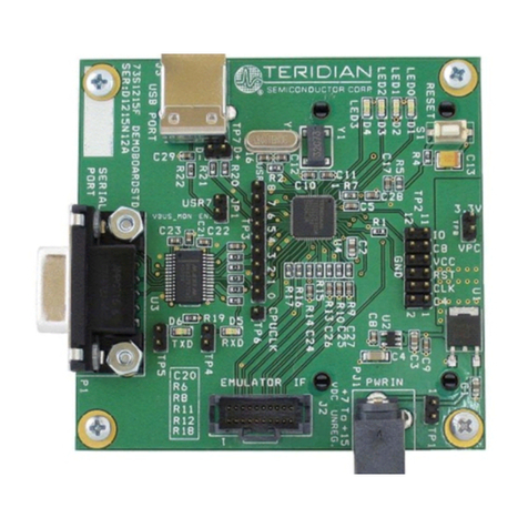
Figure 1: 73S1210F Evaluation Board Lite...............................................................................................4
Figure 2: 73S1210F Evaluation Board Lite Basic Connections.................................................................6
Figure 3: Emulator WindowShowing RESET and ERASE Buttons...........................................................8
Figure 4: Emulator Window Showing Erased Flash Memory and File Load Menu.....................................8
Figure 5: 73S1210F Evaluation Board Lite Jumper, Switch and Test Point Locations.............................12
Figure 6: 73S1210F Evaluation Board Lite Electrical Schematic.............................................................13
Figure 7: 73S1210F Evaluation Board Lite Top View (Silkscreen) ..........................................................14
Figure 8: 73S1210F Evaluation Board Lite Bottom View (Silkscreen) .....................................................15
Figure 9: 73S1210F Evaluation Board Lite Top Signal Layer..................................................................16
Figure 10: 73S1210F Evaluation Board Lite Middle Layer 1 – Ground Plane..........................................17
Figure 11: 73S1210F Evaluation Board Lite Middle Layer 2 – Supply Plane...........................................18
Figure 12: 73S1210F Evaluation Board Lite Bottom Signal Layer...........................................................19
Figure 13: External Components for RESET..........................................................................................22
Figure 14: Oscillator Circuit....................................................................................................................22
Figure 15: Smart Card Connections.......................................................................................................23
Tables
Table 1: Flash Programming Interface Signals.........................................................................................7
Table 2: Evaluation Board Lite Jumper, Switch and Test Point Description.............................................10
Table 3: 73S1210F Evaluation Board Lite Bill of Materials......................................................................20

