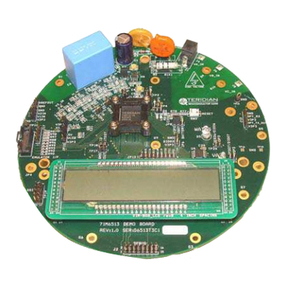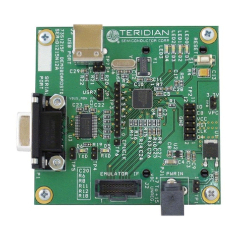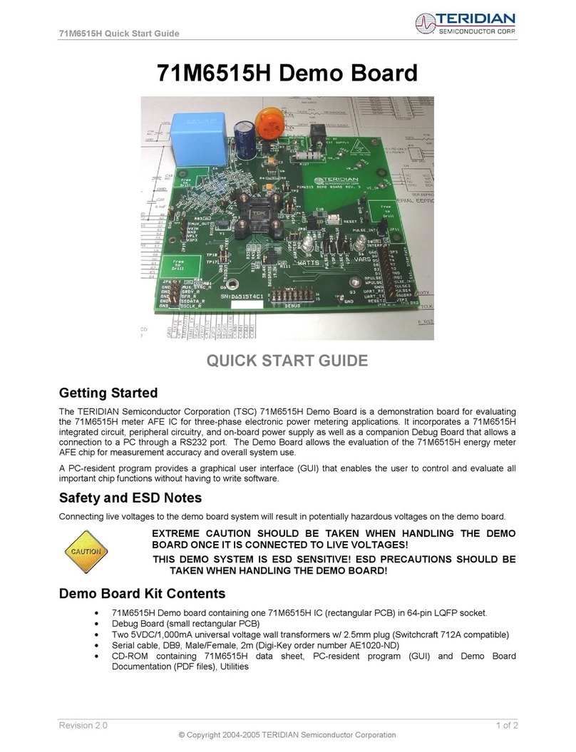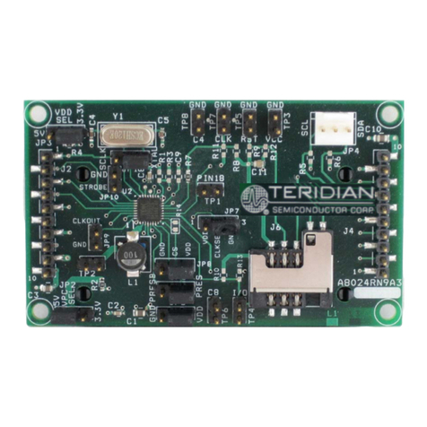
Flash Programmer Model TFP2 User’s Manual
Revision 2.3 4 of 36
Figures
Figure 2-1: CHKSUM.EXE Hex File Processing.......................................................................................7
Figure 2-2: CHKSUM.EXE Warning Display.............................................................................................8
Figure 2-3: TFP2 Power-Up Information Display......................................................................................8
Figure 2-4: TFP2 Help Menu....................................................................................................................9
Figure 2-5: TFP2 Intel Hex File Download to Internal EEPROM Command............................................11
Figure 2-6: TFP2 Select Target Intel Hex File ........................................................................................11
Figure 2-7: TFP2 Download in Progress ................................................................................................11
Figure 2-8: TFP2 Download Complete...................................................................................................12
Figure 2-9: TFP2 Download Fail due to Incorrect Memory Size Setting..................................................12
Figure 2-10: TFP2 Target Mass Erase and Program Command.............................................................13
Figure 2-11: Existing Device’s Security Bit Set.......................................................................................13
Figure 2-12: Programming Overrides Security Bit ..................................................................................13
Figure 2-13: Previously Programmed Device Check ..............................................................................14
Figure 2-14: Previously Programmed Device Check with Security Bit Set...............................................14
Figure 2-15: Device Checksum and Security Bit Status..........................................................................15
Figure 2-16: Device Checksum and Security Bit Status with Security Bit Set..........................................15
Figure 2-17: Parameter Mode Selection.................................................................................................16
Figure 2-18: Parameter Mode Status.....................................................................................................17
Figure 3-1: Memory Size Configuration..................................................................................................19
Figure 3-2: TFP2 RS-232 Connection to PC ..........................................................................................19
Figure 3-3: Port Speed, Port Bit Setup and Flow Control........................................................................20
Figure 4-1: Target-LS Connection..........................................................................................................21
Figure 4-2: Target-HS Connection.........................................................................................................21
Figure 4-3: Target-LS Connector Pin Locations (looking at TFP2 endplate)............................................22
Figure 4-4: Target-HS Connector Pin Locations (looking at TFP2 endplate)...........................................23
Figure 4-5: Standalone Configuration (shown with Target-HS cable)......................................................23
Figure 4-6: PC User Interface Configuration (shown with Target-HS cable for example).........................24
Figure 4-7: ATE Connector Pin Locations (looking at TFP2 endplate) ....................................................25
Figure 4-8: Program Flow Chart.............................................................................................................26
Figure 5-1: TFP2 Reprogram TFP2 Program Memory............................................................................27
Figure 5-2: TFP2 Boot Completion.........................................................................................................28
Tables
Table 2-1: CHKSUM Utility Addresses.....................................................................................................9
Table 2-2: CHKSUM Utility Output Data.................................................................................................10
Table 2-3: CHKSUM Utility Data Dependency........................................................................................10
Table 2-4: Parameter Space Address Location......................................................................................16
Table 3-1: RS-232 Straight Cable Connections......................................................................................20
Table 4-1: Target-LS Connector Pins.....................................................................................................22
Table 4-2: Target-HS Connector Pins....................................................................................................23
Table 4-3: ATE Connector Pins .............................................................................................................25
Table 4-4: ATE Connector Pin Input Voltage Thresholds........................................................................25
Table 4-5: ATE Connector Pin Output Voltage Levels............................................................................25


