73S8024C Demo Board User Manual UM_8024C_061
10 Rev. 1.3
Table 5: 73S8024C Miscellaneous Pins
Name Pin # Description
XTALIN 24 Crystal oscillator input: can either be connected to crystal or driven as a
source for the card clock.
XTALOUT 25 Crystal oscillator output: connected to crystal. Left open if XTALIN is being
used as external clock input.
VDDF_ADJ 18 VDD fault threshold adjustment input: this pin can be used to adjust the VDDF
values (controls deactivation of the card). Must be left open if unused.
NC 5,7 Non-connected pin.
Table 6: 73S8024C Power and Ground Pins
VDD 21 System interface supply voltage and supply voltage for internal circuitry.
VPC 6 DC-DC converter power supply source.
GND 4 DC-DC converter ground.
GND 22 Digital ground.
LIN 5 External inductor. Connect external inductor from pin 2 to VPC. Keep the
inductor close to pin 2.
Table 7: 72S8024C Microcontroller Interface Pins
Name Pin # Description
CMDVCC
Command VCC (negative assertion): Logic low on this pin causes the LDO
regulator to ramp the VCC supply to the card and initiates a card activation
sequence, if a card is present.
5V/#V 3 5 volt / 3 volt card selection: Logic one selects 5 volts for VCC and card
interface, logic low selects 3 volt operation.
When the part is to be used with
a single card voltage, this pin should be tied to either GND or VDD. However,
it includes a high impedance pull-up resistor to default this pin high
(selection of 5V card) when not connected.
PWRDN 8 Power Down control input. Active high. When the Power Down mode is set
high, all internal analog functions are disabled to place the 73S8024C in its
lowest power consumption mode. The Power Down mode is only allowed
out of a card session (i.e. when CMDVCC = 1)
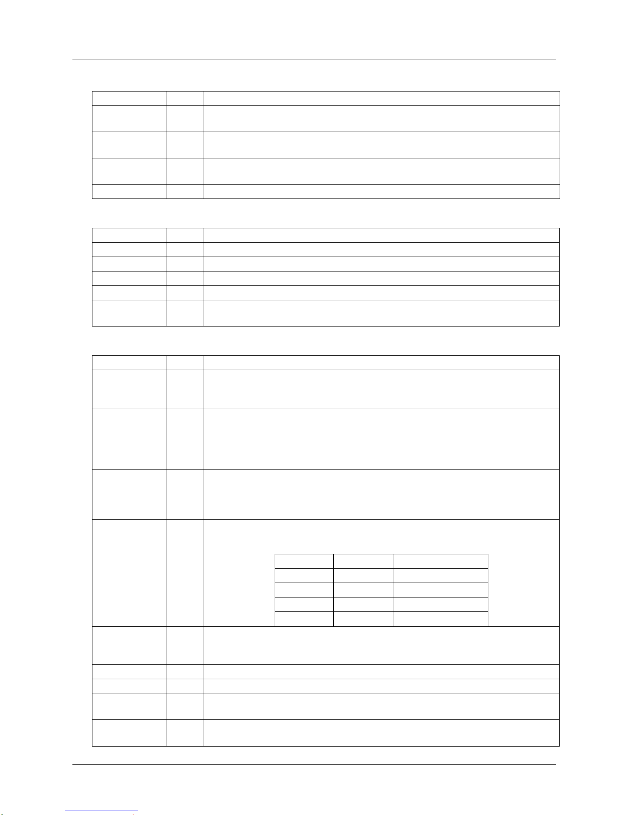
CLKDIV1
CLKDIV2
1
2 Sets the divide ratio from the XTAL oscillator (or external clock input) to the
card clock. These pins include pull-down resistors.
0 0 XTALIN/8
1 0 XTALIN
OFF 23 Interrupt signal to the processor. Active low - multi-function indicating fault
conditions and/or card presence. Open drain output configuration; includes
an internal 22 kΩ pull-up to VDD.
RSTIN 20 Reset Input: This signal is the reset command to the card.
I/OUC 26 System controller data I/O to/from the card. Includes a pull-up resistor to VDD.
AUX1UC 27 System controller auxiliary data I/O to/from the card. Includes a pull-up
resistor to VDD.
AUX2UC 28 System controller auxiliary data I/O to/from the card. Includes a pull-up
resistor to VDD.


