manuals.online logo
Brands
  1. Home
  2. •
  3. Brands
  4. •
  5. ShoreStation
  6. •
  7. Lifting System
  8. •
  9. ShoreStation SSV1564M User manual

ShoreStation SSV1564M User manual

Midwest Industries, Inc. Ida Grove, IA 51445 800-859-3028 www.shorestation.com 0004597
Page 1 of 14 Rev E 11/17/2016
SSV1564M & SSV1564ED
PWC LIFT ASSEMBLY GUIDE
MANUAL & FLEXPOWER® ELECTRIC
SSV1564M
SSV1564ED
Midwest Industries, Inc. Ida Grove, IA 51445 800-859-3028 www.shorestation.com 0004597
Page 2 of 14 Rev E 11/17/2016
Step #1 –Sort Hardware
Open the hardware box and bag and sort the hardware and other contents by size. Locate the
fastener finder sheet in the hardware box to help identify the fasteners used in the assembly of
these lifts.
Step #2 –Assemble Base Pads
Collect enough of the fasteners and items shown below to assemble four base pads. Align the
channel clamp with the holes in the base pad as shown, insert 3/8-16 x 3/4 bolts from the
bottom up and secure with 3/8 flange lock nuts. Tighten and repeat for all four base pads.
Step #3 –Assemble Base Pads to Legs
Locate the leg bundle and cut the bands to open it up. Put a 1/2-13 x 4-1/2 bolt thru the
channel clamp and the adjustable leg tube as shown and secure with a 1/2 flange locknut. The
pin will be in the leg when the corner block is installed.
Midwest Industries, Inc. Ida Grove, IA 51445 800-859-3028 www.shorestation.com 0004597
Page 3 of 14 Rev E 11/17/2016
Note that the 1/2-13 x 4-1/2 bolts should be inserted in the same direction as that of the U-bolt.
Secured so that two threads show out the end of the locknut. Repeat this process on the
remaining legs.
Step #4 –Assembly of Front and Rear Frame
Use the components included in the lower frame bundle. Your assembly will start by laying two
legs down with the corner blocks as shown. Slide a crossmember tube (63-3/4”) over the
corner block and insert the short bolt (3/8-16 x 3-1/2) with a 3/8” flat washer into the hole
closest to the post assembly. Secure with 3/8 flange locknut. The winch post leg, longest tube,
will be assembled as the left front or the right rear leg to match the lift tube assembly. Repeat
with other two legs and other crossmember. DO NOT TIGHTEN.
Midwest Industries, Inc. Ida Grove, IA 51445 800-859-3028 www.shorestation.com 0004597
Page 4 of 14 Rev E 11/17/2016
Step #5 –Attach the Side Frame Tubes
Locate the side frame tubes (81-1/4”) and with the rear legs still laying on their side, slide the
side frame tubes over the corner blocks. Insert the short bolt with a washer into the hole
closest to the post and secure on the bottom with a 3/8 flange locknut. DO NOT TIGHTEN.
Midwest Industries, Inc. Ida Grove, IA 51445 800-859-3028 www.shorestation.com 0004597
Page 5 of 14 Rev E 11/17/2016
Step #6 –Attach the Front Legs Assembly
Flip the entire assembly upright onto the base pads, and slide the side frame tubes over the
front corner leg blocks. Insert the short bolts with washers into the holes and secure on the
bottom with 3/8 flange locknuts as shown below. DO NOT TIGHTEN.
Midwest Industries, Inc. Ida Grove, IA 51445 800-859-3028 www.shorestation.com 0004597
Page 6 of 14 Rev E 11/17/2016
Step #7 –Complete Bottom Frame & Post Assembly
Locate the long bolts (3/8-16 x 4) and the bottom corner cable bracket. Only on the winch tube
side, insert the long bolt with a flat washer thru the second hole from the post, thru the frame
tubes, and then thru the corner cable bracket on the bottom as shown. Use short bolts on the
other side of the frame in the holes second from the post. Secure with a 3/8 flange locknut.
Square the frame by measuring diagonally corner to corner and tighten all hardware installed.
Midwest Industries, Inc. Ida Grove, IA 51445 800-859-3028 www.shorestation.com 0004597
Page 7 of 14 Rev E 11/17/2016
Step #8 –Assemble the Lift Platform
Lay the V-Shaped cradle tubes across the lower frame as shown. Place the end with the lift
cable threaded out the bottom on the same side as the corner cable brackets.
Attach a 3/8 carriage bolt to a plastic corner guide with a flat washer, lock washer, and locknut
as shown below on the left. Slide the corner guide with hardware into the top slot on the
outside of the cradle tube, and slide 2 carriage bolts into the top slot and 1 into the bottom slot
on the inside of the cradle tube as shown below on the right.
Longest Leg
Midwest Industries, Inc. Ida Grove, IA 51445 800-859-3028 www.shorestation.com 0004597
Page 8 of 14 Rev E 11/17/2016
Using those bolts, mount a side rail on each end of the cradle tube as shown. Position the
outer edge of the rails at least 3 inches from the end of the cradle tube. It is important to keep
this distance equal on all four corners to keep it square. Do the same on the other three
corners. DO NOT TIGHTEN.
Midwest Industries, Inc. Ida Grove, IA 51445 800-859-3028 www.shorestation.com 0004597
Page 9 of 14 Rev E 11/17/2016
The following picture shows the position of the level cable as it comes over the pulley in the
cradle tube and out the bottom to go to the corner cable bracket attached to the corner of the
lower frame. Note the other hole on the end of the cradle tube will be used later to attach the
cables coming from the bottom of the lift tube.
Step #9 –Attach the Level Cable
Attach the level cable as shown inserting the cable into the hole closest to the sideframe and
securing with a flat washer and 2 brass hex nuts. The first nut will be run to the bottom of the
threads and the second run down and secured tightly against the first. Repeat on other level
cable.
Midwest Industries, Inc. Ida Grove, IA 51445 800-859-3028 www.shorestation.com 0004597
Page 10 of 14 Rev E 11/17/2016
Step #10 –Install the Side Brace Tube / Drop Side
The side brace tube is located opposite the lift tube so install it on the posts opposite of the
corner cable brackets. The ED(electric drive) model has a drop side tube (shown below), and
the M(manual) model has a straight side brace tube. Use the appropriate brackets, bolts (3/8-
16 x 3-3/4), and washers to mount the side brace tube to the post as shown, keeping the lock
nuts on the outside. Adjust the brackets on both sides so there is about 2-1/2” between the top
of the leg and the top of the bracket, and tighten all fasteners securely.
Step # 11 –Attach the Lift (Winch) Tube Assembly
Mount the lift tube to the post as shown, keeping the lock nuts on the outside. Adjust brackets
on both sides so there is about 2-1/2” between the top of the leg and the top of the bracket on
the short leg, about 17-1/2” difference on the longer leg, and adjust it accordingly to get tension
in the level cables. Tighten all fasteners securely.
Midwest Industries, Inc. Ida Grove, IA 51445 800-859-3028 www.shorestation.com 0004597
Page 11 of 14 Rev E 11/17/2016
Step # 12 –Attach Level Cables to Spacer Brace Tube
Insert the ends of the level cables (from the cradle tubes) directly up thru the side brace tube
and secure with an aluminum washer, 1/2 flat washer, and 1/2-13 brass nut. Hint: Block the
platform off the lower frame about 6 inches to create enough slack for the cable to pass thru
the brace tube.
Midwest Industries, Inc. Ida Grove, IA 51445 800-859-3028 www.shorestation.com 0004597
Page 12 of 14 Rev E 11/17/2016
Step # 13 –Mounting Manual and Electric Winches.
Manual Winch
First, bolt the winch and the winch bracket together with 3/8-16 x 1 bolts, 3/8 flat washers, and
3/8 flange locknuts. Then use one U-bolt and one 1/2-13 x 4-1/2 bolt to attach the unit to the
corner post as shown below.
Next, slide on the wheel and spring and tighten the locknut.
Spring
Locknut
Midwest Industries, Inc. Ida Grove, IA 51445 800-859-3028 www.shorestation.com 0004597
Page 13 of 14 Rev E 11/17/2016
Electric Winch
First, bolt the winch and the winch bracket together with 1/2-13 x 1 bolts, 1/2” flat washers, and
1/2” flange locknuts. Then use one U-bolt and one 1/2-16 x 4-1/2 bolt to attach the unit to the
corner post as shown below.
Next, clamp the battery to the corner post as shown.
Midwest Industries, Inc. Ida Grove, IA 51445 800-859-3028 www.shorestation.com 0004597
Page 14 of 14 Rev E 11/17/2016
Step #14 –Attaching Upper Limit Switch
Attach the upper limit switch to the bottom of the winch tube assembly as shown. The holes
will allow the switch to be adjusted so the cable will travel thru the center of the slot in the pivot
arm. The aluminum stop with mounting hardware are to be mounted to the cable, the final
placement will not be made until the lift is in the water and the watercraft can be loaded into
the lift.
Step #15 –Inserting Caps
If you haven’t already, put the end caps on the platform. If you are adding a canopy you can
omit the corner post caps in the assembly process. The last step would be to go around and
put the black plastic caps in the top of the leg post. Before calling your assembly complete take
one last walk around your hoist and make sure all nuts and bolts have been tightened, all
cables are secured, and electrical connections are together.

This manual suits for next models

1

Other ShoreStation Lifting System manuals
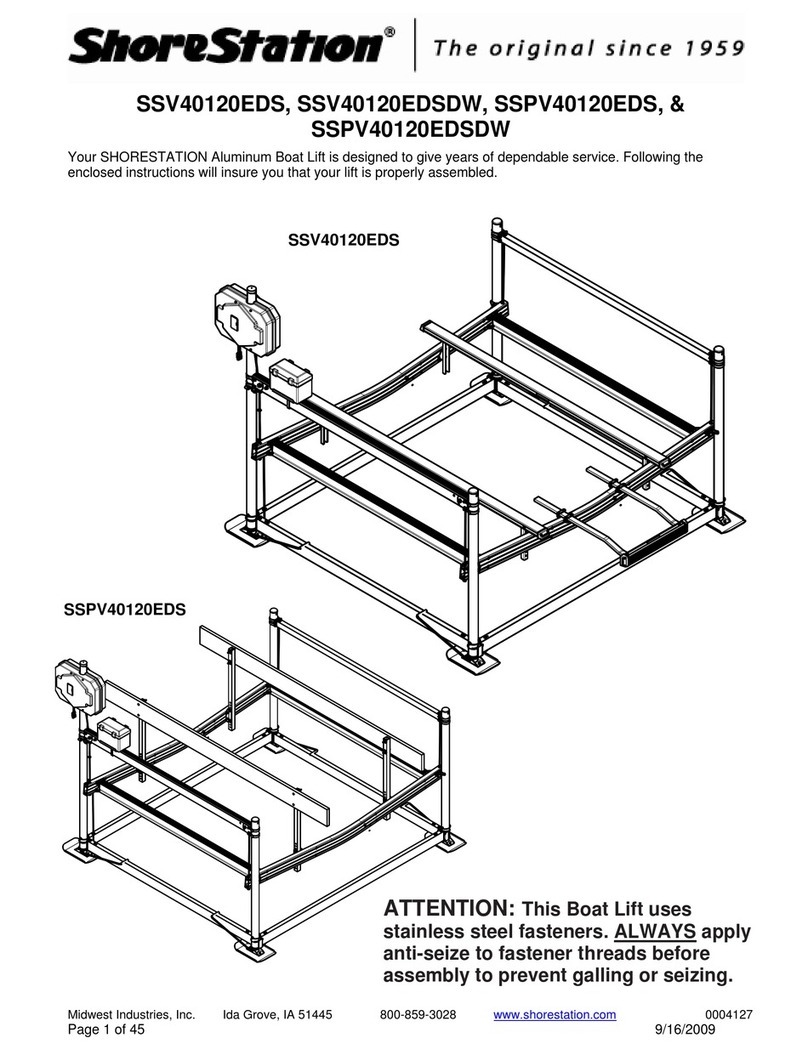
ShoreStation SSV40108EDC User manual

ShoreStation

ShoreStation SSV40108EDC User manual

ShoreStation SSV30108 User manual

ShoreStation

ShoreStation SSV30108 User manual

ShoreStation SSV30108EAC User manual

ShoreStation

ShoreStation SSV30108EAC User manual

ShoreStation FlexPower SSV30108EDS User manual

ShoreStation

ShoreStation FlexPower SSV30108EDS User manual

ShoreStation WATERFRONT SYSTEMS User manual

ShoreStation

ShoreStation WATERFRONT SYSTEMS User manual

ShoreStation Manual SSV50108MS User manual

ShoreStation

ShoreStation Manual SSV50108MS User manual

ShoreStation SSV60108MS User manual

ShoreStation

ShoreStation SSV60108MS User manual

ShoreStation Manual SSV50108MS User manual

ShoreStation

ShoreStation Manual SSV50108MS User manual

ShoreStation Manual SSV20100MS User manual

ShoreStation

ShoreStation Manual SSV20100MS User manual

ShoreStation SSV20100EAC User manual

ShoreStation

ShoreStation SSV20100EAC User manual

ShoreStation Manual SSV40120MS User manual

ShoreStation

ShoreStation Manual SSV40120MS User manual

ShoreStation SSV60108MS User manual

ShoreStation

ShoreStation SSV60108MS User manual

ShoreStation Lakefront Systems User manual

ShoreStation

ShoreStation Lakefront Systems User manual

ShoreStation Lakefront Systems User manual

ShoreStation

ShoreStation Lakefront Systems User manual

ShoreStation SS1053DE User manual

ShoreStation

ShoreStation SS1053DE User manual

ShoreStation SSV60120EDC User manual

ShoreStation

ShoreStation SSV60120EDC User manual

ShoreStation SSV15100EDC User manual

ShoreStation

ShoreStation SSV15100EDC User manual

ShoreStation SSV40120EAS User manual

ShoreStation

ShoreStation SSV40120EAS User manual

ShoreStation SSV60108EAC User manual

ShoreStation

ShoreStation SSV60108EAC User manual

ShoreStation SSV40120EAC User manual

ShoreStation

ShoreStation SSV40120EAC User manual

ShoreStation SS1564M User manual

ShoreStation

ShoreStation SS1564M User manual

ShoreStation SSV40120EDC User manual

ShoreStation

ShoreStation SSV40120EDC User manual

ShoreStation SSV30120EDC User manual

ShoreStation

ShoreStation SSV30120EDC User manual

ShoreStation FlexPower SSV40120EDS User manual
ShoreStation

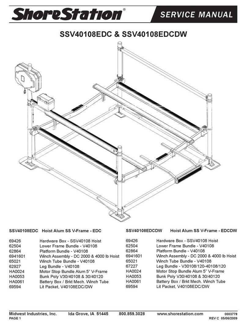
ShoreStation FlexPower SSV40120EDS User manual

Popular Lifting System manuals by other brands
SKYLOTEC Set-438 Series Instructions for use

SKYLOTEC

SKYLOTEC Set-438 Series Instructions for use

Sinoboom GTJZ0407SE Operation manual

Sinoboom

Sinoboom GTJZ0407SE Operation manual

CHIEF Pit Boss 638699 user manual

CHIEF

CHIEF Pit Boss 638699 user manual

Ravaglioli KPX315WK manual

Ravaglioli

Ravaglioli KPX315WK manual

JLG 600AJ Service and maintenance manual

JLG

JLG 600AJ Service and maintenance manual

Southworth PalletPal Walkie owner's manual

Southworth

Southworth PalletPal Walkie owner's manual

OMCN 112/A Instructions for use and maintenance / spare parts

OMCN

OMCN 112/A Instructions for use and maintenance / spare parts

Smart Lift SL 380 user manual

Smart Lift

Smart Lift SL 380 user manual

Bend-Pak HDS-18EA Installation and operation manual

Bend-Pak

Bend-Pak HDS-18EA Installation and operation manual

John Bean JLT4500S manual

John Bean

John Bean JLT4500S manual

Oshkosh Corporation JLG 830P Operation and safety manual

Oshkosh Corporation

Oshkosh Corporation JLG 830P Operation and safety manual
Sinoboom GTJZ1930SE Maintenance manual

Sinoboom

Sinoboom GTJZ1930SE Maintenance manual

Terrier TTL owner's manual

Terrier

Terrier TTL owner's manual

Snap-On EELR326A Installation and operation manual

Snap-On

Snap-On EELR326A Installation and operation manual

Sealey MC455.V2 Instructions for use

Sealey

Sealey MC455.V2 Instructions for use

Waverley Glen C450 owner's manual

Waverley Glen

Waverley Glen C450 owner's manual

Tuxedo PL6K Installation and operation manual

Tuxedo

Tuxedo PL6K Installation and operation manual

Genie Z-45/25 Operator's manual

Genie

Genie Z-45/25 Operator's manual

manuals.online logo
manuals.online logoBrands
  • About & Mission
  • Contact us
  • Privacy Policy
  • Terms and Conditions

Copyright 2025 Manuals.Online. All Rights Reserved.