TESTO Hygrotest 600 WH User manual

Hygrotest 600
WH / WHT -20/+70 °C
DH / DHT -20/+70 °C / DHT -20/+120 °C
PHT -20/+70 °C / PHT -20/+120 °C
Instruction manual en

Contents
Introduction
2
EMC according to guideline 2004/108/EEC
Introduction........................................................................................................................2
Handling instructions..........................................................................................................3
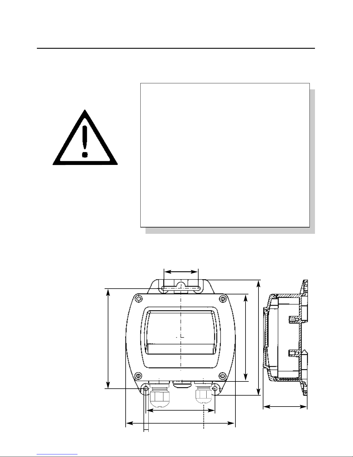
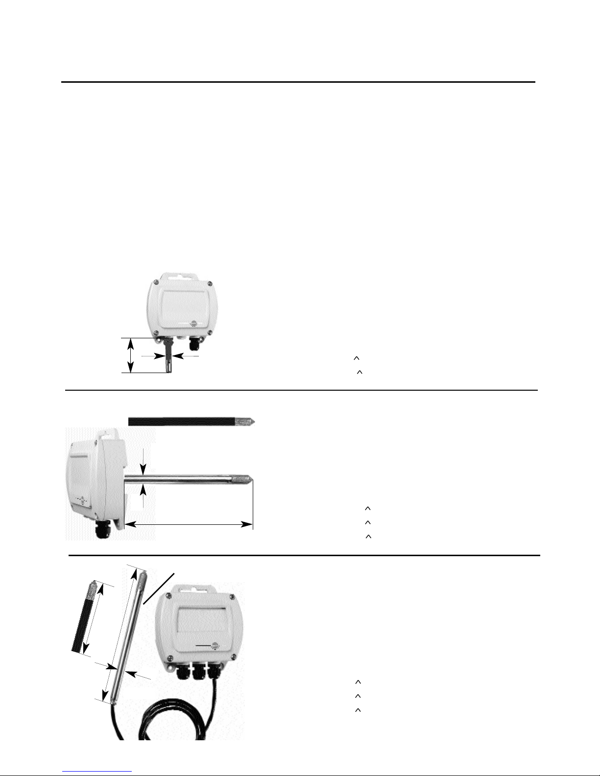
Dimensions of measuring instrument ................................................................................3
Description of functions ....................................................................................................4
Standard versions ..............................................................................................................5
Version options ..................................................................................................................6
Connection assignment ....................................................................................................8
Description of 2 wire technology ........................................................................................8
Connection suggestions for 2 wire technology ..................................................................9
Current measurement ..................................................................................................9
Voltage measurement ................................................................................................10
Attaching ferrite sleeve ....................................................................................................11
Installing a digital display..................................................................................................11
Advice on use ..................................................................................................................12
Adjustment ......................................................................................................................13
Adjustment with testo 650/400..................................................................................13
Adjustment with control and adjustment set ..............................................................14
Maintenance ....................................................................................................................15
Cleaning the humidity sensor ....................................................................................15
Technical data..................................................................................................................16
Ordering data ..................................................................................................................17
Dear Customer
Thank you for purchasing a Testo product. We hope you will enjoy the benefits of this product for a long
time to come and that it will aid you with your work.
Please read this instruction manual carefully and familiarise yourself with the operation of the instrument
before putting it to use.
If problems should occur which you cannot rectify yourself, please consult our Customer Service
Department or your nearest distributor. We will do our best to help you quickly and competently to
avoid downtimes.

Please read prior to operation!
Do not measure on live parts!
Observe sensor measuring ranges!
The probes may be damaged if overheated.
Observe maximum storage and transport temperature
as well as maximum operating temperature
(e.g. protect instrument from direct sunlight).
The warranty is invalid if inexpertly handled or force is
used !
Installation, adjustment and calibration work should only
be carried out by trained professionals.
Handling instructions
Dimensions of instrument
in mm
3
52
105
120*
5.1*
140
82.5*
M20x1.5 M16x1.5 M16x1.5
41*
* Mounting dimensions
130
Opening Ø 5 mm
Note
The cable lead-ins differ
depending on version

The affordable transmitters from the hygrotest 600
series have been developed for a wide variety of HVAC
applications but also for industrial drying processes, for
example. Depending on design the modular design
facilitates wall assembly, duct assembly as well as
measurements at inaccessible points (probe can be
attached to pipe).
The transmitters can be easily calibrated and adjusted
on-site via a control and adjustment set (see adjustment
guidelines). The user saves time and money when
assembling and installing thanks to the industrial
standard 4 to 20mA in 2 wire technology and the
variable assembly options (rail, wall, duct, separate
probes).
Advantages of hygrotest 600
Ideal price/performance ratio:
- Electronics immune to interference thanks to reverse
battery protection, overvoltage protection, EMC
compliance to industrial standards
- Electrical isolation
- Low installation and assembly costs thanks to
industrial 4 to 20 mA 2 wire technology
- Easy on site calibration and adjustment for humidity
and temperature via adjustment set
- LED display (optional)
- RS 485 Interface (optional)
Description of functions
4

5
For monitoring ambient air conditions using an
external humidity and temperature probe (temperature
output only in Hygrotest 600 WHT).
For duct measurement in compact design using an
external humidity and temperature probe.
With an external humidity and temperature probe,
2 m long cable, maximum
hygrotest 600 WH
hygrotest 600 WHT -20/+70 °C
hygrotest 600 DH
hygrotest 600 DHT -20/+70 °C
hygrotest 600 DHT -20/+120 °C
hygrotest 600 PHT -20/+70 °C
hygrotest 600 PHT -20/+120 °C
Standard versions
210
100
12
12
12
65
200
1.4571
DH / DHT 70
Plastic (70°C version)
Plastic (70° C version)
Scaling: 4 to 20mA = 0 to 100% RH
4 to 20mA = 20 to +70 °C (WHT 20/+70 °C)
Scaling: 4 to 20mA = 0 to 100% RH
4 to 20mA = 20 to +70 °C (DHT 20/+70 °C)
4 to 20mA = 20 to +120 °C (DHT 20/+120 °C)
Scaling: 4 to 20mA = 0 to 100% RH
4 to 20mA = -20 to +70 °C (PHT -20/+70 °C)
4 to 20mA = -20 to +120 °C (PHT -20/+120 °C)
Ter ms
W: Wall H: Humidity
D: Duct T: Temperature
P: Probe -20/+70 °C: Standard scaling -20/+70 °C
Part no. for hygrotest 600 product series: 0555.0600
Example:
hygrotest 600 PHT / -20/+70 (cable version with external probe, with humidity and
temperature measurement up to + 70 °C)
Stainless steel 1.4571
(120°C version)
Stainless steel 1.4571
(120°C version)

6
Version options
Analog output
B 1 4 to 20 mA (2-wire-technology)
Probe
Probe material stainless steel 1.4571
Probe material plastic
C 1 Standard probe length incl. sensor protection filter 65 65 200 200 200 100 210
C 2 Special probe length, stainless steel incl. sensor protection cap........
DH -20/+120°C: min 100mm; PHT -20/+120°C: min. 150mm; max. 800mm
C 3 Special probe length, plastic, 100 mm, incl. sensor protection cap
Cable
D 1 Standard cable length 2 m
D 2 Special cable length up to tip of probe .......m (min. 250 mm; max.2 m)
Adjustment
F 1 Humidity inaccuracy ±2 %RH
Sensor protection caps
G 1 Stainless steel sintered cap
G 2 Wire mesh filter
G 3 PTFE sintered filter
G 4 Slid metal filter
G 5 ABS-cap slit
Displays
H 1 Display double-spaced - loop feed with maximum load 50 Ohm
H 2 Display double-spaced - external supply with max. load 500 Ohm
H 3 Display double-spaced - with RS485 - no analog outputs possible
H 4 Display double-spaced - with RS485 -analog output possible
H 5 Display double-spaced with RS485 and 2x2 limit signal outputs - analog outputs possible
600 DH
600 DHT
-20/70
600 DHT
-20/120
600 PHT
-20/70
600 PHT
-20/120
Order Code
600 WH
600 WHT
-20/70

Version options
7
- standard - optional
H 6 Display double-spaced with 2x2 limit signal outputs - analog outputs possible
H 7 Simple display single-space - loop feed with maximum load 50 Ohm
Scaling
K 1 Standard scaling channel 1 (4 to 20 mA = 0 to 100 %RH)
K 2 Special scaling channel 1 (4 to 20 mA = ...... choosen unit out of “L”
Note: please specify the scaling range
L 1 Realtive humidity (%RH)
L 2 Dewpoint (°Ctd)
L 3 Dewpoint (°Ftd)
M 1 Standard scaling channel 2 (4 to 20 mA = temperature scaling (°C) -20/70 -20/70 -20/120-20/70 -20/120
M 2 Special scaling channel 2 (4 to 20 mA = ...... choosen unit out of “N”
Note: please specify the scaling ranges
N 1 Temperature (°C)
N 2 Temperature (°F)
600 DH
600 DHT
-20/70
600 DHT
20/120
600 PHT
20/70
600 PHT
-20/120
Order Codes
600 WH
600 WHT
-20/70

8
Connection assignment
1 + RH 2 wire techn. 4 to 20 mA = 0 to 100 %RH,
2 - RH
2 wire techn. 4 to 20mA = -20 to +70 °C
(with WHT -20/70 / DHT -20/70 / PHT -20/70)
2 wire technology 4 to 20 mA = -20 to +120°C
(with DHT -20/120 / PHT -20/120)
4 - °C
3+°C
In order to avoid losing the adjustment values,
adjustment buttons should only be activated if the
adjustment container is screwed on (see page 10,
adjustment with control and adjustment set).
}
}
^
^
2 wire transmitters are used to convert non-electrical
parameters, e.g. temperature, pressure,
relative humidity etc. to an electrical standard signal of 4
to 20 mA.
The transmitters are connected to a d.c. voltage source
by means of 2 cables. The power consumption of the
transmitter from the d.c. current source changes linearly
in the range from 4 to 20 mA, depending on the
parameter being measured.
The advantages of the two wire system are easy
installment and problem-free connection. The length of
the cables does not influence the measured signal. A
further additional advantage is the so-called “live zero”
signal i.e. 0 parameter corresponds to a current of 4
mA. In this way, this value is also clearly transmitted and
cannot be confused, for example, with a system which
is switched off or an ununterrupted line.
Description of 2 wire technology
Connection socket
for scaling adapter
or testo 400/650
instrument for
1-point adjustment
1 2 3 4

9
4 to 20 mA = -20 to
+120°C / +70°C
for WHT/DHT/PHT
Connection suggestions
for 2 wire technology
Current measurement
Option 1:
Option 2:
4
3
2
1
Transmitter
4 to 20 mA = 0 to +100 %RH
24 V
DC
4
3
2
1
Transmitter
4 to 20 mA = -20 to +120°C/+70°C
for WHT/DHT/PHT
4 to 20 mA = 0 to +100 %RH
hygrotest 600 with displays H1, H3, H7 is supplied
via the humidity connections. The temperature output,
if available, can only function if a humidity circuit with
24 V is connected. This also applies in combination
with all displays.
230V/
110V
230V/
110V

10
Voltage measurement
Long signal paths can be a problem when transmitting
voltage signals (cable resistance, interference etc.).
It is advisable to use current signals for safe
transmission (4 to 20 mA).
Shunt resistances between 50 Ω or 500 Ω (50 Ω: 0.2 to
1 V, 500 Ω: 2 to 10 V) are parallel connected to the
multimeter, controller etc. when measuring voltage (0.2
to 1 V, 2 to 10 V) (see Figure).
Advantage
- Reliable signal due to power transmission
- Recognises disconnected cable (“live zero”)
Voltage measurement from 2 to 10 V or 2 to 10 V is
not possible in instruments with displays H1, H3, H7
since they are loop-fed.
Connection suggestions
for 2 wire technology
4
3
2
1
Transmitter
0.2...1V (2...10V) = -20...+70 °C
0.2...1V (2...10V) = 0...+100 %RH
50Ω
(500Ω)
50Ω
(500Ω)
%RH


Bohrvorlage für Messwertumformer hygrotest 600
Drilling template for the transmitter hygrotest 600
82,5mm
125mm
66mm
66mm
51mm
ø 5mm
66mm
Bohrdurchmesser ist ab-
hängig von der Montageart.
Drilling hole diameter de-
pends on mounting type.
für D-Varianten
for D versions


11
Attaching ferrite sleeve
for 2 wire technology
Max. load 50 Ω with displays H1, H3, H7
Installing a digital display
- Remove housing cover from hygrotest 600.
Disconnect electrical supply.
- In displays H1, H7 move right slide switch (SW11)
from the bottom position to the upper OFF position
(Fig. 1). In displays H2, H3, H4, H5, H6 switch
remains on ON position.
- Remove 4 screws from the instrument board (Fig.1).
- Attach cable connector (Fig. 2) of display (watch
out for guide pin) to connection socket (Fig. 1).
- Screw in spacing pins on instrument board (Fig. 3).
- Mount display board with screws on spacing pins.
- Perform electrical connection.
- Screw on new housing cover (with window)
Slide
switch
Screws
Cable
connector
Spacing pins
Fig. 1
Fig. 3
Fig. 2
Connection socket
for
scaling adapter or
testo 400/650
instrument for
1-point adjustment
Note
To comply to EMC rules, all outside cables have to
carry ferrite sleeves. These sleeves are delivered with
the instrument. Please insert the analog output signal
cable of each channel through one of the sleeves (out-
side the housing).

12
Advice on use
The hygrotest 600 humidity and temperature transmitter is
employed in a wide variety of industrial applications. Some
advice which can lead to better measuring results is given
below.
General
The better the process air flows past the probe, the sooner
the transmitter will display the correct temperature and
humidity.
- Low flow rate and uncontaminated atmosphere
Use slotted sensor caps (0554.0755) to achieve a faster
response time.
- Atmosphere containing dust or particles
Use a PTFE sintered cap (0554.0647) to protect the
sensor against contamination.
- Strong flow rates up to 10 m/s with few particles
Use a stainless steel sintered cap (0554.0647).
- Flow rates >10 m/s or lots of particles
Fit a deflector in the direction of flow and mount the
probe away from the wind with a suitable sintered cap.
- Applications in which drips may form
Install the probe in such a way that condensate can run
off. Use dew protection (0554.0166)(see drawing). You
may need to use a PTFE sintered cap with a drill hole
(0554.9913).
- Measuring humidity in chemical gases
Gas concentrations deviating from the natural ambient
atmosphere may have an influence on the values or
damage the humidity sensor.
-For installation support please contact your local testo
partner.
Seal

13
Adjustment
If the testo 650/400 is used for adjustment, you will also
need the cable, Part no. 0409.0214 and precision
humidity probe 0636.9741.
Note
The following describes a 1-point adjustment. This is
only advised if hygrotest 600 is operated close to the
adjustment point (working point).
Before opening the transmitter:
- interrupt the control circuit of the transmitter;
1. Remove the cover of the transmitter.
2. Plug the connecting cable into the micromatch
connection on the transmitter board or display board
(see diagram).
3. Set up transmitter control circuit.
If you are using a display, you must interrupt
communication between the display and the
transmitter. To do this, press the key for at least
3 seconds. Communication of the display is
interrupted and the display unit shows dashes
(- - - -).
4. Plug the precision humidity probe into the right port
and the connecting cable into the left port of the
testo 650 or testo 400 reference instrument.
5. Attach the precision humidity probe immediately
adjacent to the probe of the transmitter in order to
obtain comparable values.
6. Switch on testo 650/400. The two-part display will
show the values of the transmitter on the left, and the
values of the reference instrument on the right.
Two options are available for adjustment:
1. Adjustment with the reference instrument testo
650/400 and precision humidity probe from testo.
2. Adjustment with reusable saturated salt solutions
11.3 %RH and 75.3 %RH (control and adjustment
set).
Adjustment with testo 650/400
Caution!
Heated
humidity probe Reference
probe
26.4%rF 27.2%rF
25.1°C 26.2°C
Micromatch connection
Display port and port for scaling
adapter or handheld instrument for
adjustment. Protection pin on right

14
Adjustment
1. Remove the sensor cap.
2. Note the immersion depth of the probe.
3. Screw the humidity container to the probe with a
suitable adapter.
4. Perform the adjustment at a constant temperature.
5. Wait to the end of the compensation period
(recommended: >6h).
6. Carry out adjustment. To do this, press the key for the
corresponding values (11.3 %RH or 75.3 %RH) and the
“Enable” key at the same time (see top drawing on
page 13).
Note
The adjustment period is at least 180 minutes at a
constant temperature of 25 °C.
Note
For the adjustment process, if a display is connected
(H1, H2, H3, H4, H5 or H6), please refer to the “Display”
instruction manual.
7. Push on OK button of the testo 400/650. Choose
menu ”probe”. Press OK again and choose menu
”Adjustment”. After a further push of the OK button the
humidity and temperature value of the testo 400/650 is
sent to Hygrotest. Humidity adjustment in the
transmitter is cancelled via ”Probe Reset” and set back
to previous values.
Now take off the cable between testo 400/650 and the
Hygrotest transmitter.
8. If you are using a display, reestablish communication
between the display and the transmitter by pressing the
key briefly.
9. Close the transmitter and reestablish connections.
Note
To ensure accuracy, use a regularly calibrated reference
instrument and precision humidity probe to carry out the
adjustment.
Note
An adjustment period of at least 60 minutes is advised
at a constant temperature of 25°C.
Note
Adjustment of the transmitter is possible from firmware
version 1.22 in the testo 650 or testo 400.
Adjustment with control and adjustment set
A 2-point humidity adjustment of the transmitter can be
performed using the control and adjustment set.
For other adjustment instructions, please refer to the
“Control and adjustment set” instruction manual.

15
Maintenance
Cleaning the sensor
For cleaning the humidity sensor isopropanol should be
used. Not suitable is spirit, as spirit contains small tracks
of oil.
Rinse the humidity sensor in isopropanol until no dirt is
visible anymore. Afterwards wash up the humidity sensor
with distilled water.
Do not towel the sensor with a cloth, as the lid electrode
could be damaged.

16
hygrotest 600
Technical data
Outputs can be scaled
Pressure tightness
of probe: 4 bar (DHT 20/120 / PHT
20/120), at +10 to +40°C
Vacuumtightness
of probe: Approx. 0.5 bar (DHT 20/
120 / PHT 20/120)
The other types are designed for atmospheric
conditions.
Electrically isolated
outputs: Humidity and temperature
(WHT, DHT, PHT only )
Power supply: 24 V DC (10 to 30 V DC)
Max. load without
display: At 10 V, 100 Ohm
At 18 to 30 V, 500 Ohm
Max. load with
display H1: 20 to 30 V, 50 Ohm
Power supply with
display H1: At least 20 V
Reaction time: t90 approx. 10 to 20 s
We recommend an
integration time of 1s
in the case of very quick
analog recorders or PLC
inputs.
Temperature resistance
Probe and cable: 120 °C (DHT 20/120 /
PHT 20/120)
70 °C (WH, WHT 20/70,
DH, DHT 20/70, PHT 20/70)
EMC: according Guidline 89/336
EEC
Probe material: Polycarbonate(PC)
except with DHT 20/120 /
PHT 20/120, here 1.4571
stainless steel is used.
All data referring to a rated temperature +25°C.
Warranty 2 years
Housing:
Material: ABS, grey colour RAL 7035
Dimensions: 130 x 105 (140) x 52 mm
Humidity sensor: Testo sensor
plugged in with:
DHT 20/+120°C and
PHT 20/+120°C
With other types the sensor is
soldered
Temp. sensor NTC
plugged in with:
DHT 20/+120°C and
PHT 20/+120°C
With other types the sensor is
soldered
Screw connections: 2 x M 16 x 1.5
Ambient temp.: 0 to +70 °C
Storage temp.: 40 to +80 °C
Protection class: IP 65
Measuring ranges:
Humidity: 0 to 100% RH
Temperature: 20 to +70 °C (WHT 20/70/
DHT 20/70 / PHT 20/70
20 to +120 °C
(DHT 20/120 /PHT 20/120)
Temp. coefficient: 0.05%RH/°C for temp.
deviating from 25°C
Accuracy
Humidity: ±2% RH (0 to 90 %RH)
±3% RH (90 to 100 %RH)
Accuracy
Temperature: ±0.3 °C (20 to +50 °C)
1.5% of reading >50 °C
Analog outputs:
Humidity
Resolution: 0.02 mA
Accuracy: 0.04 mA
Drift: 0.001 mA/°C
Temperature
Resolution: 0.02 mA
Accuracy: 0.04 mA
Drift: 0.003 mA/°C
Humidity and
temperature: 4 to 20 mA in 2 wire
technology (WHT, DHT, PHT
only)
This manual suits for next models
4
Table of contents
Other TESTO Measuring Instrument manuals
Popular Measuring Instrument manuals by other brands

Keba
Keba KeContact E10 instructions

MKS
MKS Granville-Phillips Mini-Convectron 275... instruction manual

Tektronix
Tektronix 492, 492P Service manual

Maxim
Maxim Lase-Align Kit User instructions

Precision Digital Corporation
Precision Digital Corporation Loop Leader PD6600 Series instruction manual

Omega Engineering
Omega Engineering i Series user guide