Teuco 2WSC18 User manual
ISTRUZIONI DI MONTAGGIO
ASSEMBLY INSTRUCTIONS
INSTRUCTIONS POUR LE MONTAGE
MONTAGE-ANWEISUNGEN
INSTRUCCIONES DE MONTAJE
MONTAGE-INSTRUCTIES
INSTRUÇÕES PARA A MONTAGEM
ИHCTPYK ЦИЯ ПO MOHTAЖY
√¢∏°π∂™ ∂°∫∞∆∞™∆∞™∏™
INSTRUKCJE MONTAŻU
MONTAJ TALIMATLARI
UPUTSTVA ZA MONTAÏU
HR
TR
PL
GR
RU
P
NL
E
D
F
GB
I
626
627
626
627
2
Leggere le AVVERTENZE e le istruzioni descritte in
questo manuale.
Read the WARNINGS and the instructions
described in this manual.
Lire les AVERTISSEMENTS et les instructions
contenus dans ce manuel.
Lesen Sie die HINWEISE und die Anleitungen in
diesem Handbuch.
Leer las ADVERTENCIAS y las instrucciones que
contiene este manual.
Lees de RICHTLIJNEN en de instructies uit deze
handleiding door.
Leia as ADVERTÊNCIAS e as instruções descritas
neste manual.
Внимательно прочитайте содержащиеся в
настоящем руководстве ПРАВИЛА и
инструкции.
¢È·‚¿ÛÙ ÙȘ ¶ƒ√∂π¢√¶√π∏™∂π™ ηÈ
ÙȘ Ô‰ËÁ›Â˜ ÙÔ˘ ·ÚfiÓÙÔ˜ ÂÁ¯ÂÈÚȉ›Ô˘.
Zapoznać się z OSTRZEŻENIAMI i instrukcjami
podanymi w niniejszym podręczniku.
Bu kitapçıkta açıklanmakta olan UYARILAR
ve talimatları dikkatlice okuyunuz.
Proãitajte NAPOMENE i savjete navedene u
ovim uputstvima.
HR
TR
PL
GR
RU
P
NL
E
D
F
GB
I
(1) - A livello dello skimmer • At height of skimmer • Au niveau du skimmer • Auf Höhe des Skimmer • A nivel del skimmer • Op niveau van de skimmer• Ao nível do skimmer • на уровне
переливного отверстия • ™ÙÔ ‡„Ô˜ ÙÔ˘ skimmer • Na poziomie cedzidła • Filtre seviyesi •Do razine skimmera
(2) - Prima di collegare il prodotto accertarsi che i dati di targa siano rispondenti a quelli della rete di distribuzione elettrica
(2) - Before making any electrical connections, check that the rated voltage and current of the appliance are matched to the mains power supply.
(2) - Avant de raccorder l’hydrodouche, s’assurer que les données de la plaquette correspondent aux données du réseau de distribution électrique.
(2) - Überprüfen Sie vor dem Stromanschluß die Entsprechung von Schild- und Netzwerten
(2) - Antes de conectar el producto a la red de electricidad hay que comprobar si las características de la misma coinciden con las que figuran en la placa de datos del
producto.
(2) - Alvorens het product aan te sluiten, dient u zich ervan te verzekeren dat de gegevens op het typeplaatje overeenstemmen met de kenmerken van het elektrische
voedingsnet.
(2) - Antes de ligar o produto, certifique-se de que os dados da chapa de características correspondem aos da rede de distribuição eléctrica.
(2) - Прежде чем выполнить электрические соединения проверьте соответствие указанных на табличке изделия номинальных данных с
характеристиками сети электроснабжения.
(2) - ¶ÚÈÓ Û˘Ó‰¤ÛÂÙ ÙÔ ÚÔ˚fiÓ, ‚‚·Èˆı›Ù fiÙÈ Ù· ¯·Ú·ÎÙËÚÈÛÙÈο Ù˘ ÈӷΛ‰·˜ ·ÓÙÈÛÙÔÈ¯Ô‡Ó Û ÂΛӷ ÙÔ˘ ËÏÂÎÙÚÈÎÔ‡ ‰ÈÎÙ‡Ô˘.
(2) - Przed wykonaniem podłączeń elektrycznych należy sprawdzić czy dane znamionowe urządzenia są odpowienie dla elektrycznej instalacji zasilającej.
(2) - Herhangi bir elektrik ba¤lantısı yapmadan önce cihazın nominal voltaj ve akımının ana güç hattına eflde¤er oldu¤undan emin olunuz.
(2) - Prije nego ‰to prikljuãite ure√aj provjerite da li su podaci navedeni na ploãici primjereni napojnoj elektriãnoj mreÏi.
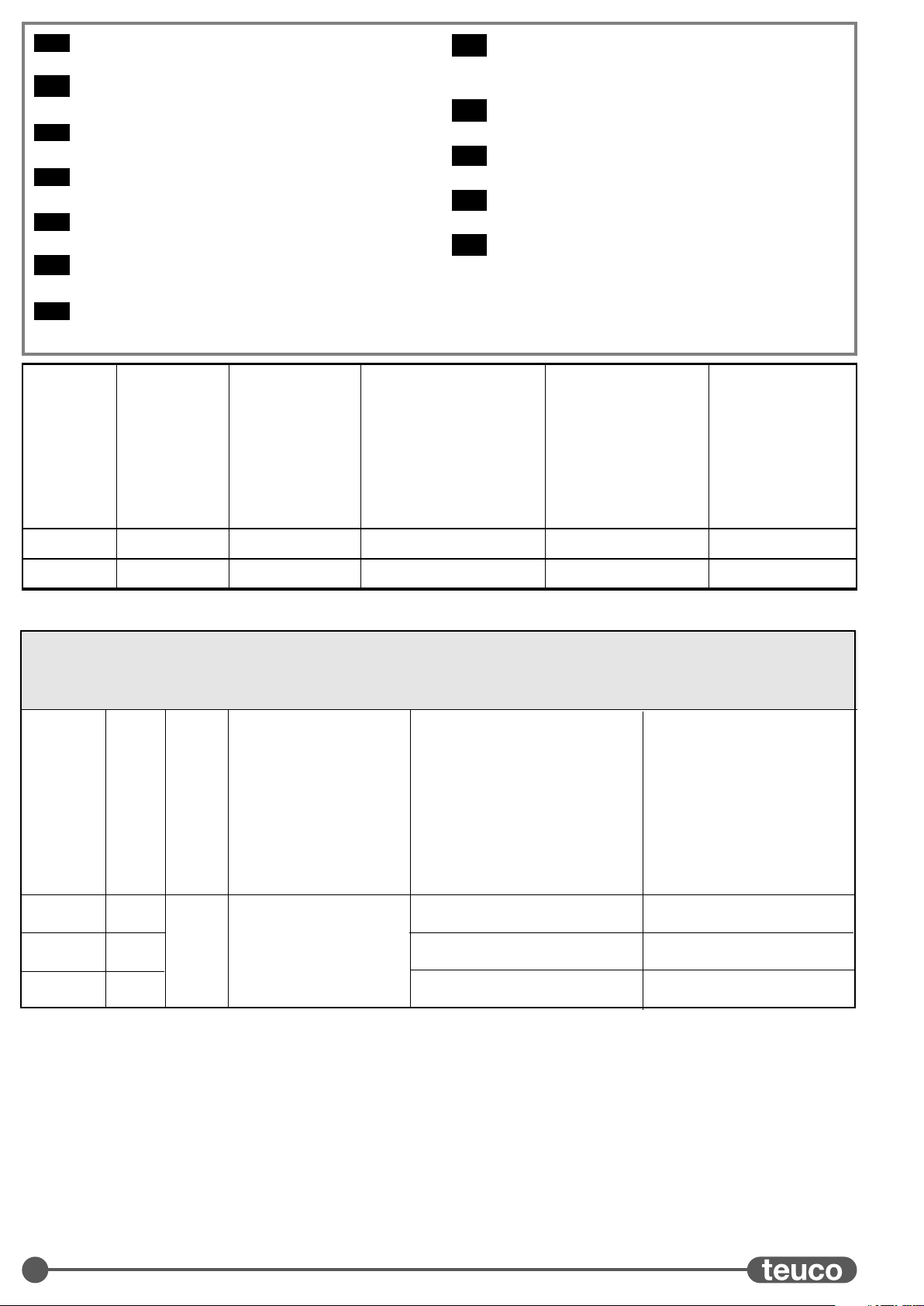
Peso netto
Net weight
Poids net
Nettogewicht
Peso neto
Netto gewicht
Peso líquido
Вес нетто
∫·ı·Úfi ‚¿ÚÔ˜
Ciężar netto
Net a¤ırlık
Neto teÏina
242 kg
ART.
626
Carico sul pavimento
Floor load
Charge au sol
Bodenbelast
Carga al pavimiento
Belasting op de vloer
Carga sobre pavimento
Нагрузка на полу
µ¿ÚÔ˜ ÛÙÔ ‰¿Â‰Ô
Obciążenie podłoża
Zemin yükü
Optereçenje poda
490 kg/m2
Contenuto acqua
Water capacity
Contenance eau
Wasserinhalt
Volumen de agua
Waterinhoud
Conteúdo água
Количество воды
ÈÚËÙÈÎfiÙË-Ù· ÓÂÚÔ‡
Pojemność wody
Su Kapasitesi
Nosivost vode
870 lt.
(1)
Peso di spedizione
Shipping weight
Poids emballage compris
Versandgewicht
Peso de expedición
Verzendgewicht
Peso expedição
Вес упакованного изделия
µ¿ÚÔ˜ ·ÔÛÙÔÏ‹˜
Ciężar podczas transportu
Nakliye a¤ırlı¤ı
TeÏina po‰iljke
329 kg
Volume di spedizione
Shipping volume
Cubage
Versandvolumen
Volumen de expedición
Verzend-volume
Volume expedição
Объем упаковки
ŸÁÎÔ˜ ·ÔÛÙÔÏ‹˜
Objętość podczas transportu
Nakliye Hacmi
Zapremnina ambalaÏe
5,5 m3
290 kg627 510 kg/m2
870 lt.
(1)
377 kg 5,5 m3
CARATTERISTICHE ELETTRICHE
(2)
• ELECTRICAL SPECIFICATIONS
(2)
• CARACTÉRISTIQUES ÉLECTRIQUES
(2)
• ELEKTRISCHE DATEN
(2)
•
CARACTERÍSTICAS ELÉCTRICAS
(2)
• ELEKTRISCHE KENMERKEN
(2)
• CARACTERÍSTICAS ELÉCTRICAS
(2)
• ЭЛЕКТРИЧЕСКИЕ
ХАРАКТЕРИСТИКИ
(2)
•∏§∂∫∆ƒπ∫∞ Ã∞ƒ∞∫∆∏ƒπ™∆π∫∞
(2)
• CHARAKTERYSTYKI ELEKTRYCZNE
(2)
•ELEKTR‹KSEL
KARAKTER‹ST‹KLER
(2)
•ELEKTRI
â
NI PODACI
(2)
Modello
Model
Modèle
Modell
Modelo
Model
Modelo
Модель
ªÔÓÙ¤ÏÔ
Model
Model
Model
VHz
400 50 0,16 Kw
230
-
-
4WSR29
3WSR28
230
2WSC18
3,9 Kw
2,6 Kw
Assorbimento massimo versione con scambiatore di calore
Maximum power consumption: version with heat exchanger
Consommation maxi version avec échangeur de chaleur
Max. Stromaufnahme in Ausführung mit Wärmetauscher
Absorción máxima versión con intercambiador de calor
Max. stroomopname bij uitvoering met warmtewisselaar
Absorção máxima versão com comutador de calor
Максимальная потрeбляeмая мощность модeли с
тeплообмeнником
ª¤ÁÈÛÙË Î·Ù·Ó¿ÏˆÛË ÌÔÓÙ¤ÏÔ˘ Ì ÂÓ·ÏÏ¿ÎÙË ıÂÚÌfiÙËÙ·˜
Maksymalny pobór mocy w wersji z wymiennikiem ciepła
Maksimum sarfiyat: ısı eflanjörlü versiyon
(Maksimalna potro‰nja) modela s izmjenjiv aãem topline
Assorbimento Max versione con riscaldatore
Maximum power consumption: version with heater
Consommation maxi version avec réchauffeur
Max. Stromaufnahme in Ausführung mit Zusatzheizung
Absorción máxima versión con calefactor
Max. stroomopname bij uitvoering met verwarmingselement
Absorção máx. versão com aquecedor
Максимальная потрeбляeмая мощность
модeли с нагрeватeлeм
ª¤ÁÈÛÙË Î·Ù·Ó¿ÏˆÛË ÌÔÓÙ¤ÏÔ˘ Ì ıÂÚÌ·ÓÙ‹Ú·
Maksymalny pobór mocy w wersji z ogrzewaczem
Maksimum sarfiyat: ısıtıcılı versiyon
(Maksimalna potro‰nja) modela s grijaãem
Assorbimento solo ricircolo
Power consumption (recirculation only)
Consommation recyclage uniquement
Stromaufnahme nur Umwälzung
Absorción sólo recirculación
Stroomopname hercirculatie
Absorção apenas recirculação
Потребляемая мощность при
включенной рециркуляции
∫·Ù·Ó¿ÏˆÛË ÌfiÓÔ Ì ·Ó·Î‡ÎψÛË
Pobór mocy tylko przy recyrkulacji
Tek sirkülasyon sarfiyatı
Potro‰nja same recirkulacije
1,9 Kw -
3
2740
1640
2965
S
2165
800 65
10
Sez.: A-A
B
A
A
A
788
688
695
AA
min.400 min.400
884
773
261 261
773
884
261 261
773 773
884 884
968
1016
1063
1016
968
968
968
1016
1063
1016
788 788
688 688
633 633
542 542
428 428
700 400
400 400
1640
AA
BB
1445
1340
2165
1445
1340
1AART. 626
4
230
300
380
645175
820 820
430
1082,51082,5
OC1C
1640
AA
BB
2165
A-A
2165
915 65
980
A-A
2165
915 65
980
788
688
695
500
638
590
1445
1340
1B
2
ART. 627
5
3
4
6
5a
(4,5x25)
x9
AA
BB
11
22
33
CC
5b
7
min. 4 m
6b
6a
M10x40
M10
8
Ø40mm
CALDAIA
3/4"
3/4"
7
8
9
9

10
(4,5x25)
x9
11
22
33
AA
BB
CC
10
11
11
-Istruzioni di Montaggio 626-627..................................................................12
-Assembly Instructions 626-627 ..................................................................14
-Instructions pour le Montage 626-627....................................................16
-Montage-Anweisungen 626-627..................................................................18
-Instrucciones de Montaje 626-627 ............................................................20
-Montage-Instructies 626-627.........................................................................22
- IInstruções para a Montagem 626-627....................................................24
-Инструкция по монтажу 626-627...................................................26
-√‰ËÁ›Â˜ ÂÁηٿÛÙ·Û˘ 626-627.....................................................28
-Instrukcje montażu 626-627..................................................................30
-Model 626-627 - Montaj Talimatları ......................................32
-Uputstva za montaÏu 626-627 .........................................................34
HR
TR
PL
GR
RU
P
NL
E
D
F
GB
I

12
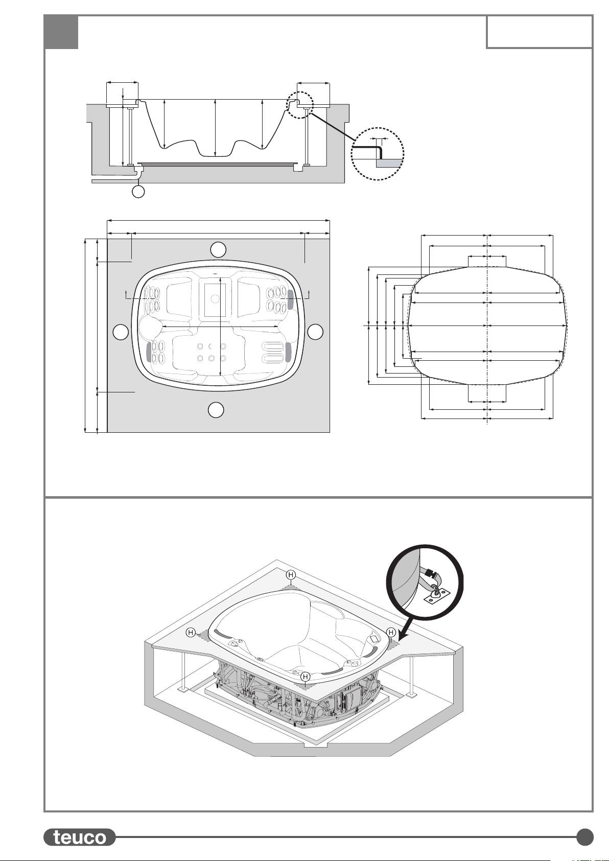
PREISTALLAZIONE Art. 626-627
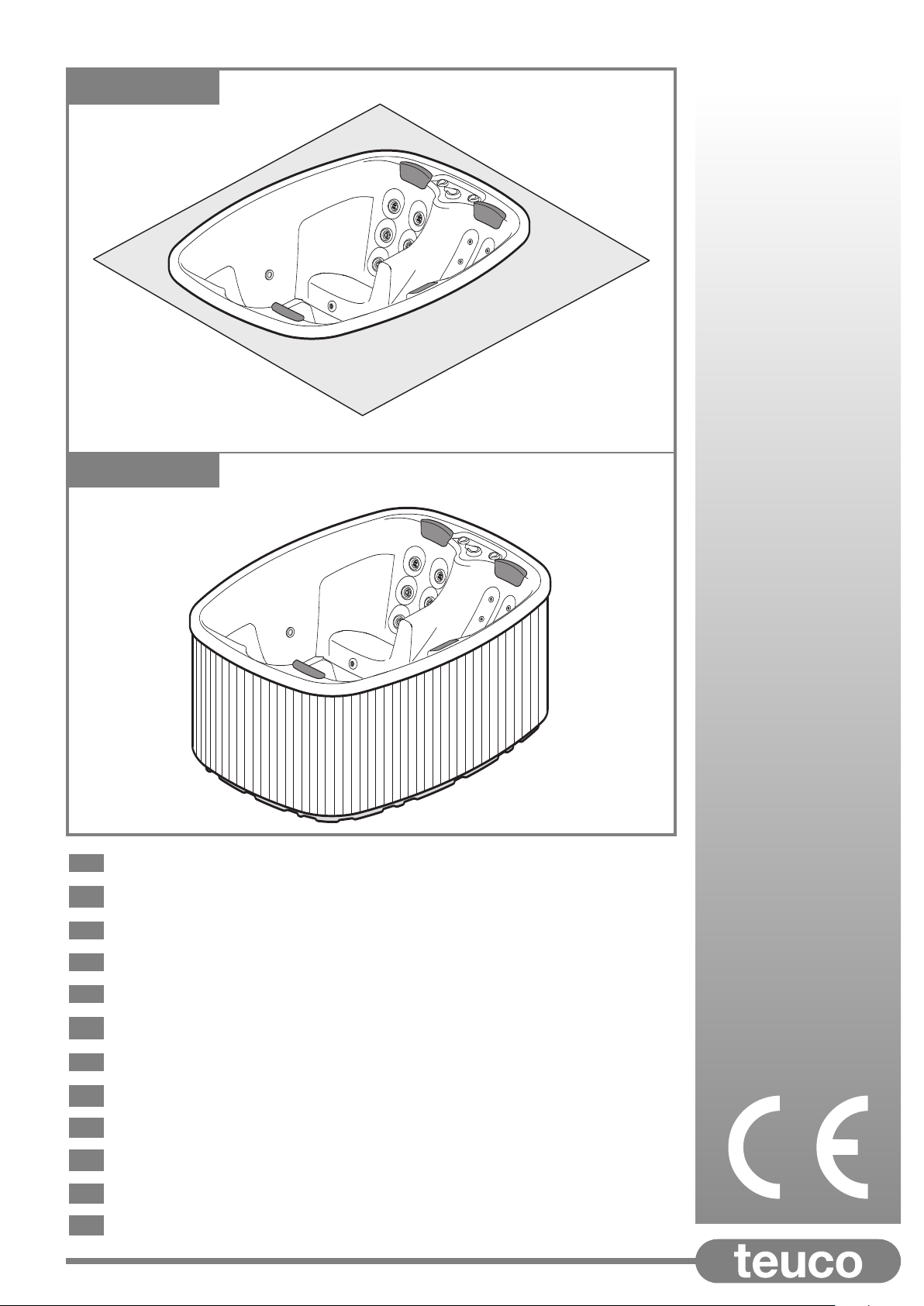
ART. 626 - MINIPISCINA DA INCASSO
PREDISPOSIZIONE DELL’INCASSO
Realizzare il vano per l’alloggiamento della minipiscina in
calcestruzzo, rispettando le misure indicate nel disegno e facendo
attenzione che sia perfettamente livellato.
La base di appoggio della minipiscina deve avere una portata di
633 Kg/m2.
Predisporre un corridoio (A) di almeno 40 cm di larghezza su tutto
il perimetro e di 70 cm nella zona (B) della minipiscina per
garantire l’accessibilità all’impianto idraulico ed elettrico istallati
sotto la minipiscina.
Tale corridoio deve essere chiuso con pedane removibili sorrette
da adeguati sostegni; le pedane devono garantire una sufficiente
areazione del vano con aperture di almeno 0,3 m2.In
corrispondenza degli angoli della Minipiscina (zone H) sulle
pedane dovranno essere predisposti opportuni ancoraggi per la
copertura (vedi disegno).
Realizzare sul fondo del vano un sistema di raccolta e scarico (S)
per evitare eventuali ristagni d’acqua.
ART. 627 - MINIPISCINA CON PANNELLI
PREDISPOSIZIONE BASE DI APPOGGIO
Realizzare la base di appoggio della minipiscina per una
portata di 643 Kg/m2.
Fare attenzione che la base di appoggio sia perfettamente
livellata.
Se la minipiscina viene istallata all’aperto (es.: su di un prato)
realizzare la base di appoggio con un fondo stabilizzato che ne
garantisca l’opportuna stabilità.
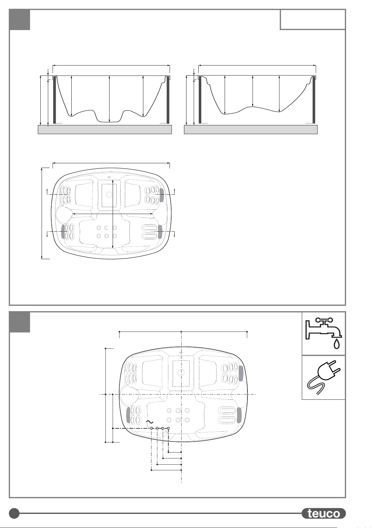
PREDISPOSIZIONE ALLACCI
ALLACCI IDRAULICI
O - Allaccio di scarico ø 40 mm.
(solo per istallazione fissa - facoltativa)
C- Allaccio per scambiatore di calore (alla caldaia) 3/4"
C1 -Allaccio per scambiatore di calore (dalla caldaia) 3/4"
- Punto di uscita cavo per l’allaccio elettrico
N.B. Gli allacci (C) e (C1) sono previsti solo nel caso la minipiscina
sia fornita di scambiatore di calore.
SCARICO
La minipiscina Teuco é dotata di valvola di fondo con attacco ø
40 mm. Per lo scarico si può utilizzare un tubo flessibile da
collegare alla valvola, oppure si può effettuare un collegamento
fisso con la tubazione di scarico (O). In questo caso per
agevolare lo scarico si consiglia la predisposizione di un
pozzetto con valvola, da utilizzare come valvola di fondo.
ATTENZIONE: Prima di predisporre il pozzetto di scarico,
consultare le autorità locali per le normative che regolano
lo scarico di acqua trattata chimicamente.
CARICO
Per il riempimento della minipiscina Teuco è consigliato l’utilizzo
di un tubo flessibile esterno, avendo cura di non immergerlo per
evitare un eventuale riflusso dell’acqua nella rete idrica.
ATTENZIONE: Nel caso di collegamento fisso della
minipiscina alla rete idrica è necessaria l’adozione di
opportuni dispositivi in grado di salvaguardare la rete
idrica da fenomeni di riflusso.
Consultare le autorità locali prima di effettuare tale tipo di
istallazione.
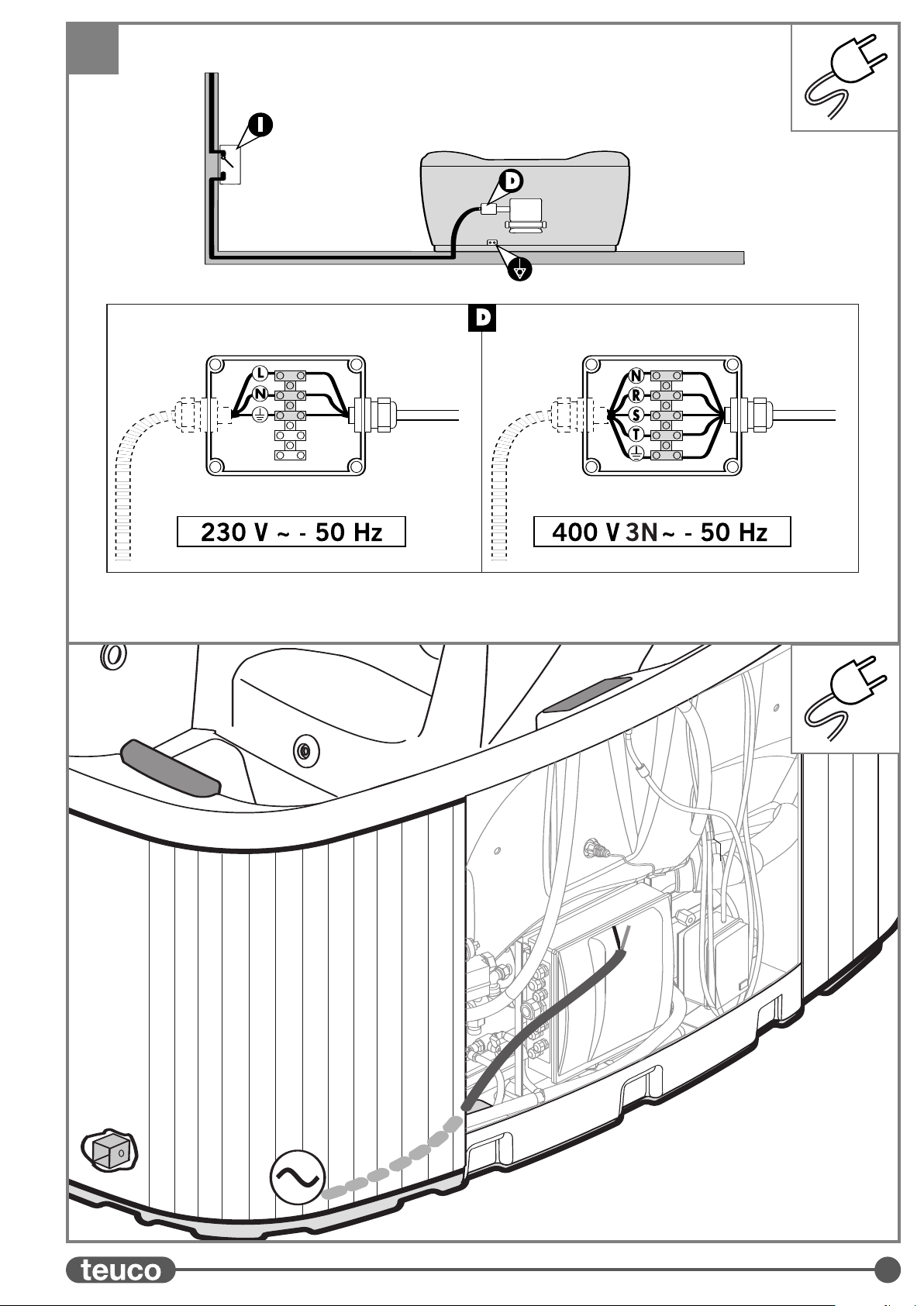
ALLACCI ELETTRICI
L’impianto elettrico di alimentazione deve essere conforme alla
norma CEI 64-8.
Il prodotto deve essere collegato alla rete attraverso un
interruttore onnipolare con apertura minima dei contatti di 3mm
posizionato al di fuori delle zone 0,1,2 (CEI 64-8/7).
Verificare che il prodotto sia alimentato attraverso un
interruttore differenziale con soglia di intervento ≤30mA.
Il collegamento alla rete deve comprendere la connessione
all’impianto di terra e deve essere:
- di tipo fisso
- adeguato alla corrente assorbita (vedi dati di targa)
- con grado di resistenza alla penetrazione dei liquidi
(IPX5).
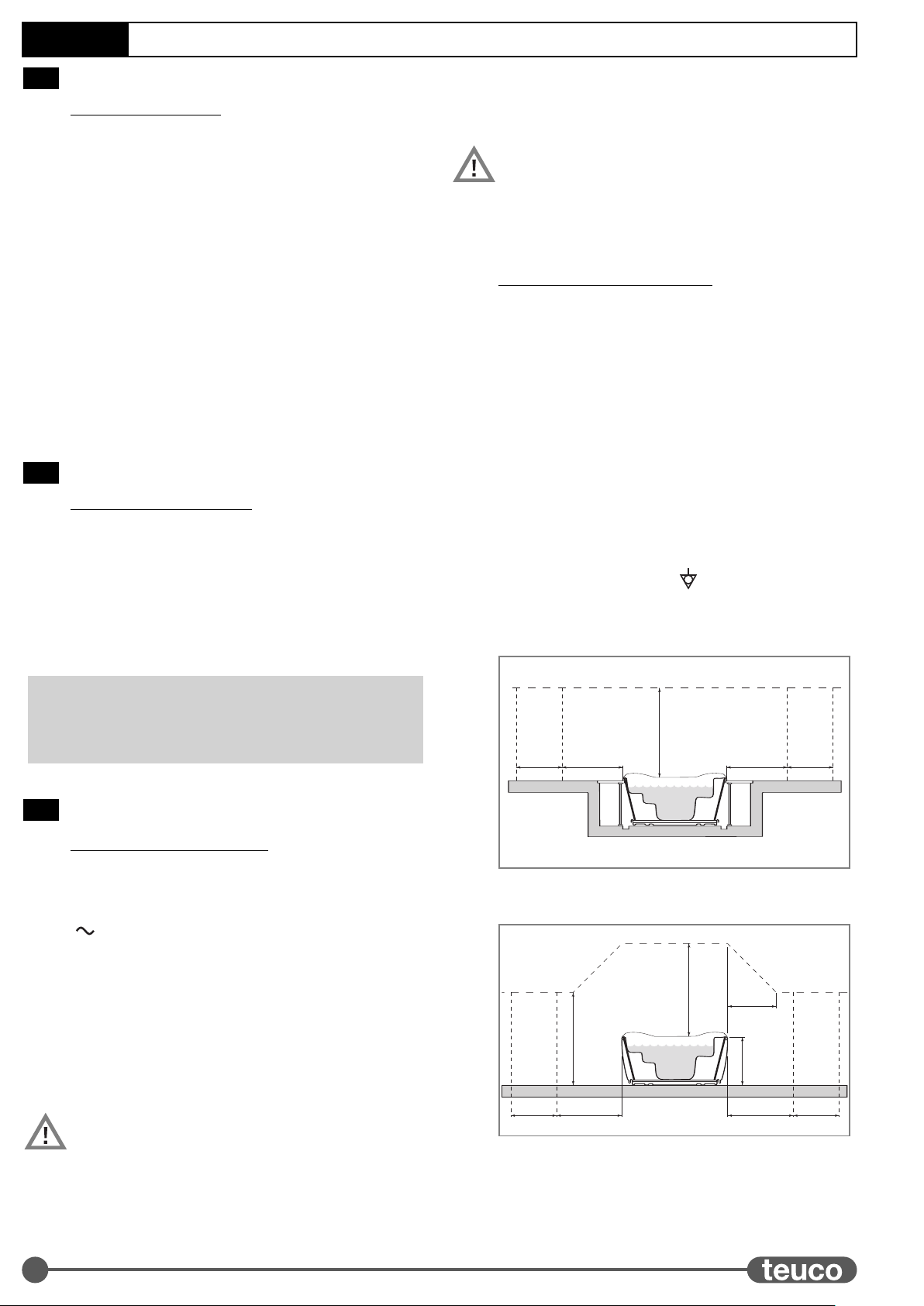
Il prodotto deve essere collegato all’insieme equipotenziale
tramite l’apposito morsetto ( ) posizionato sul telaio
metallico.
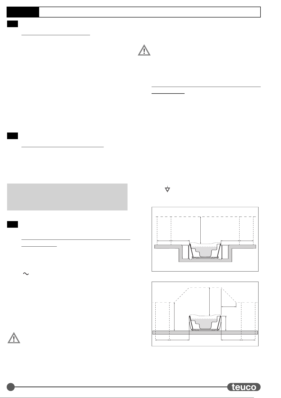
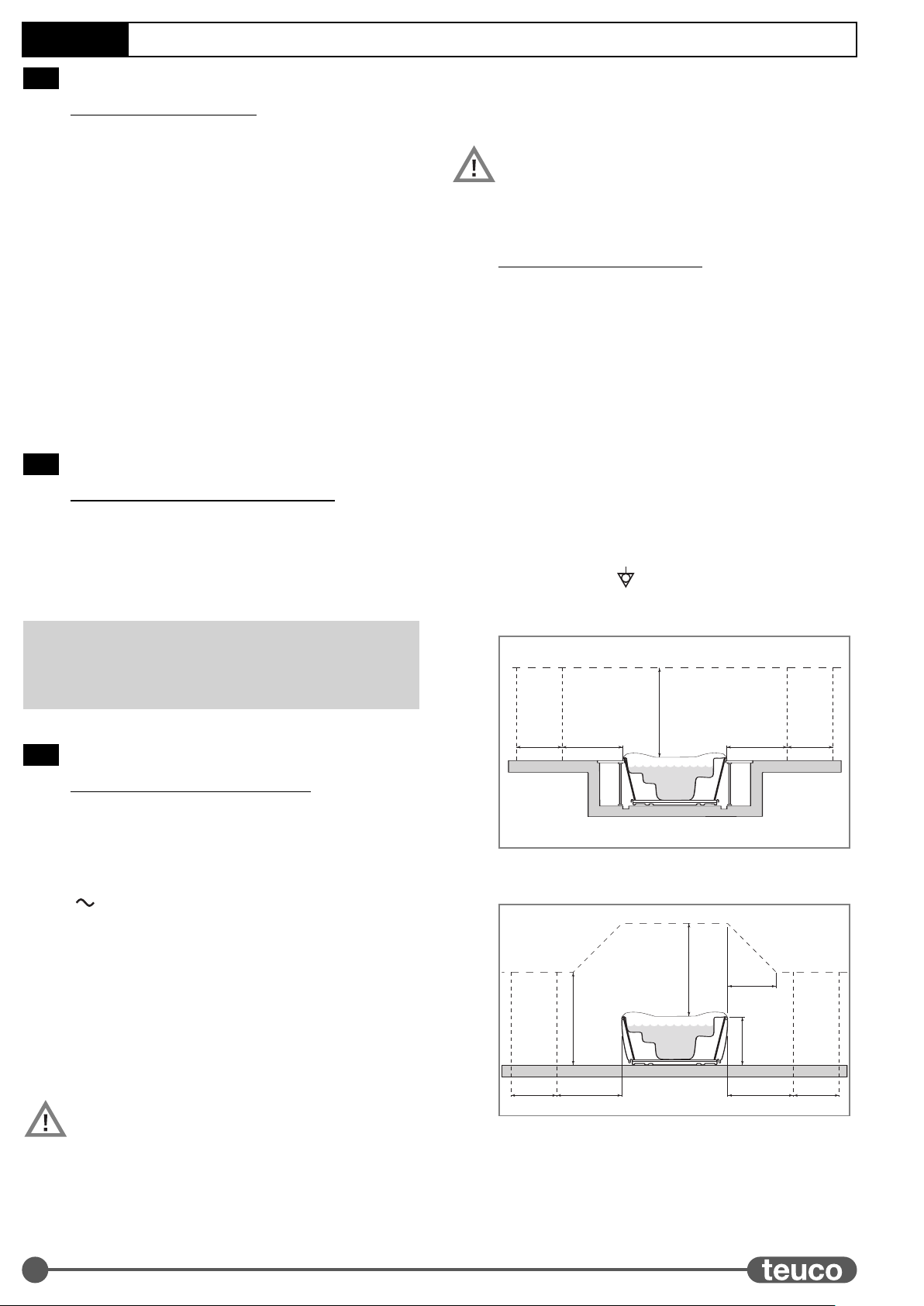
Vasca Incasso (CEI 64-8/7)
Vasca con pannelli (CEI 64-8/7)
2,5 m
2 m1,5 m 2 m 1,5 m
ZONA 2 ZONA 2
ZONA 1
ZONA 0
ZONA 0
2,5 m
h
= h
2,5 m
2 m1,5 m 2 m 1,5 m
ZONA 2 ZONA 2ZONA 1
ZONA 0
ZONA 0
2
VENTILAZIONE DELL’AMBIENTE
Nel caso di istallazione in ambiente chiuso è necessario
provvedere ad una adeguata ventilazione dell’ambiente stesso.
1B
1A
IT
13
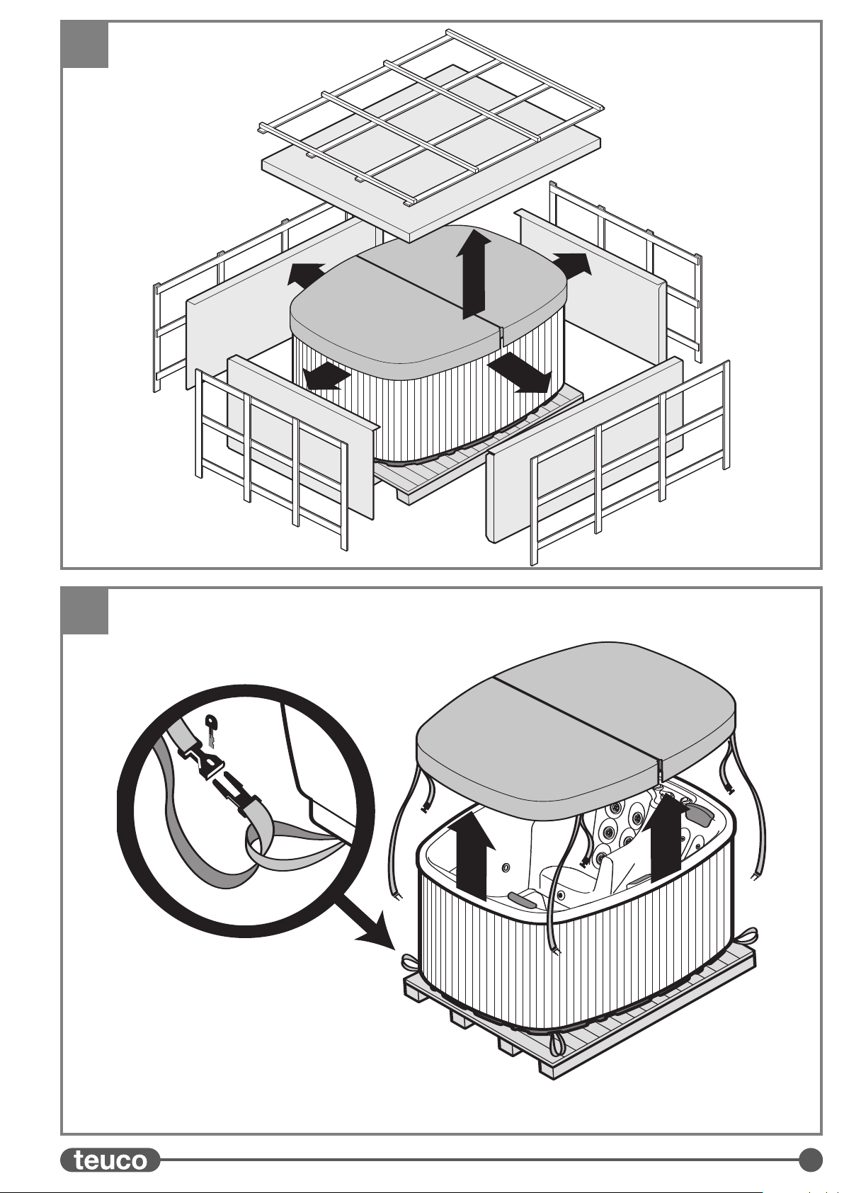
APERTURA DEL’IMBALLO
Liberare la minipiscina dall’imballo lasciandola sul pallet.
Per tutte le operazioni di trasporto servirsi esclusivamente del
pallet su cui appoggia la minipiscina.
SMONTAGGIO DELLA COPERTURA
Togliere la copertura (solo per art.627 sganciare le cinghie di tenuta
poste sugli angoli della minipiscina).
La copertura non é concepita per sostenere pesi.
Non sedersi, camminare o sdraiarsi sulla copertura.
Non depositarvi oggetti.
La copertura non fissata o non chiusa può essere pericolosa.
Non seguire le istruzioni di fissaggio della copertura può risultare
pericoloso per l’utilizzatore.
Rimuovere completamente la copertura prima di entrare nella
minipiscina; si può rimanere incastrati.
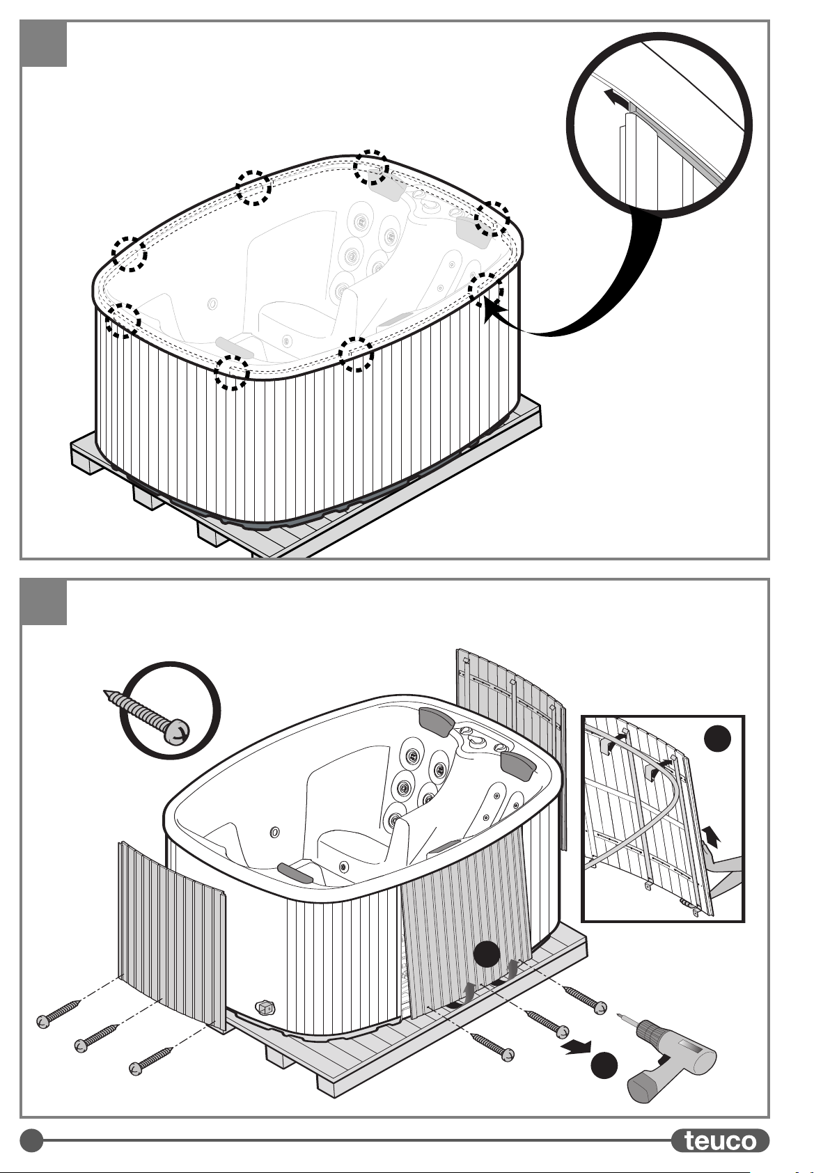
SMONTAGGIO DEI PROFILI
Rimuovere i profili di protezione alloggiati tra il bordo e la pannellatura
della minipiscina.
SMONTAGGIO DEI PANNELLI IN LEGNO
Svitare le viti (A) alla base dei pannelli e tirarli verso se (B) in modo che
escano dalle rispettive sedi.
Sollevare il pannello fino a sganciare le parti superiori (C) per poi
toglierlo dalla struttura che lo blocca seguendo l’ordine numerico.
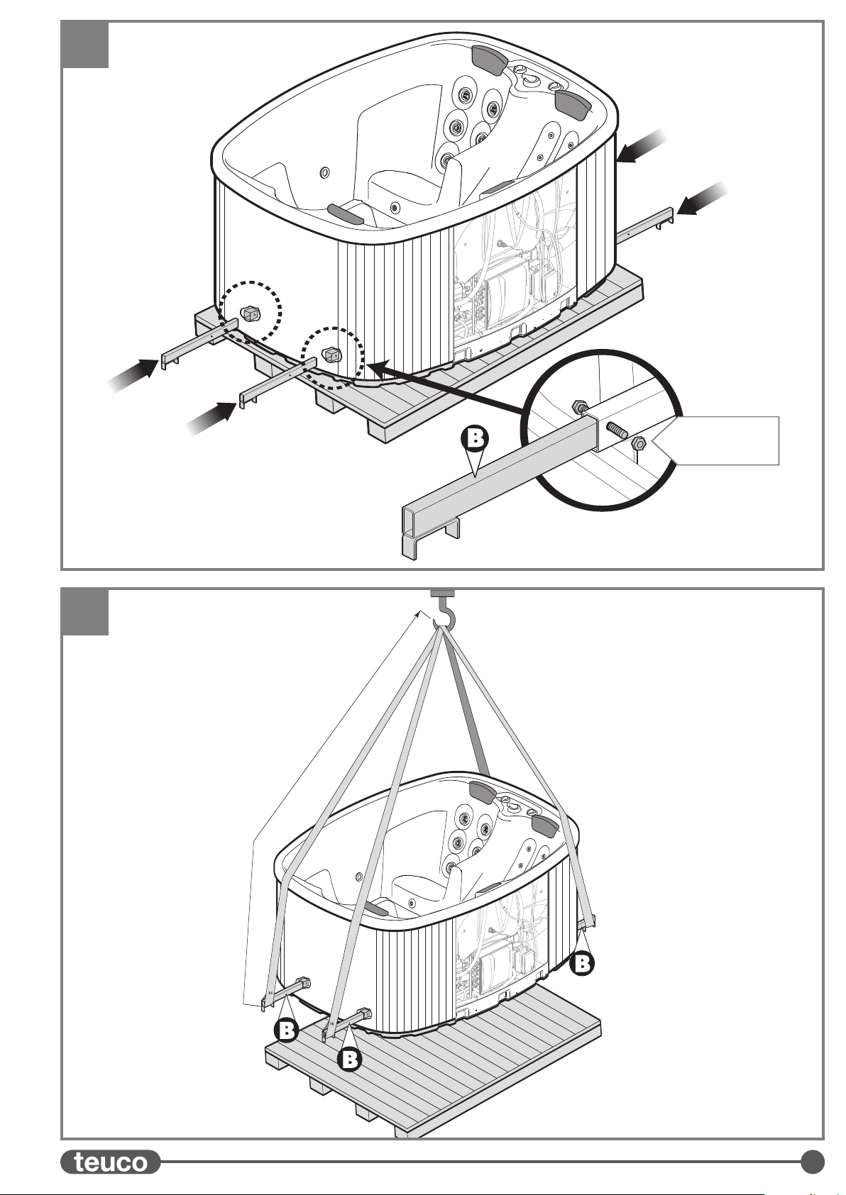
MONTAGGIO DELLE BARRE DI SOLLEVAMENTO
Inserire le barre di sollevamento sui lati del telaio bloccandole
con le apposite viti con dado.
NON SOLLEVARE MAI LA MINIPISCINA PRENDENDOLA
PER IL BORDO O PER LE TUBAZIONI.
LA MINIPISCINA NON DEVE ESSERE MAI SOLLEVATA
PIENA D’ACQUA.
POSIZIONAMENTO IN OPERA
Per il posizionamento in opera usare cinghie di portata adeguata e
con una lunghezza di almeno 4 metri (distanza tra barre della
minipiscina e gancio di sollevamento).
Agganciare le cinghie sulle barre (B) e sollevare la minipiscina
posizionandola nel luogo stabilito (il peso a vuoto della minipiscina é di
circa 350 Kg).
Rimuovere le barre (B) lasciandole da parte per eventuali interventi
futuri.
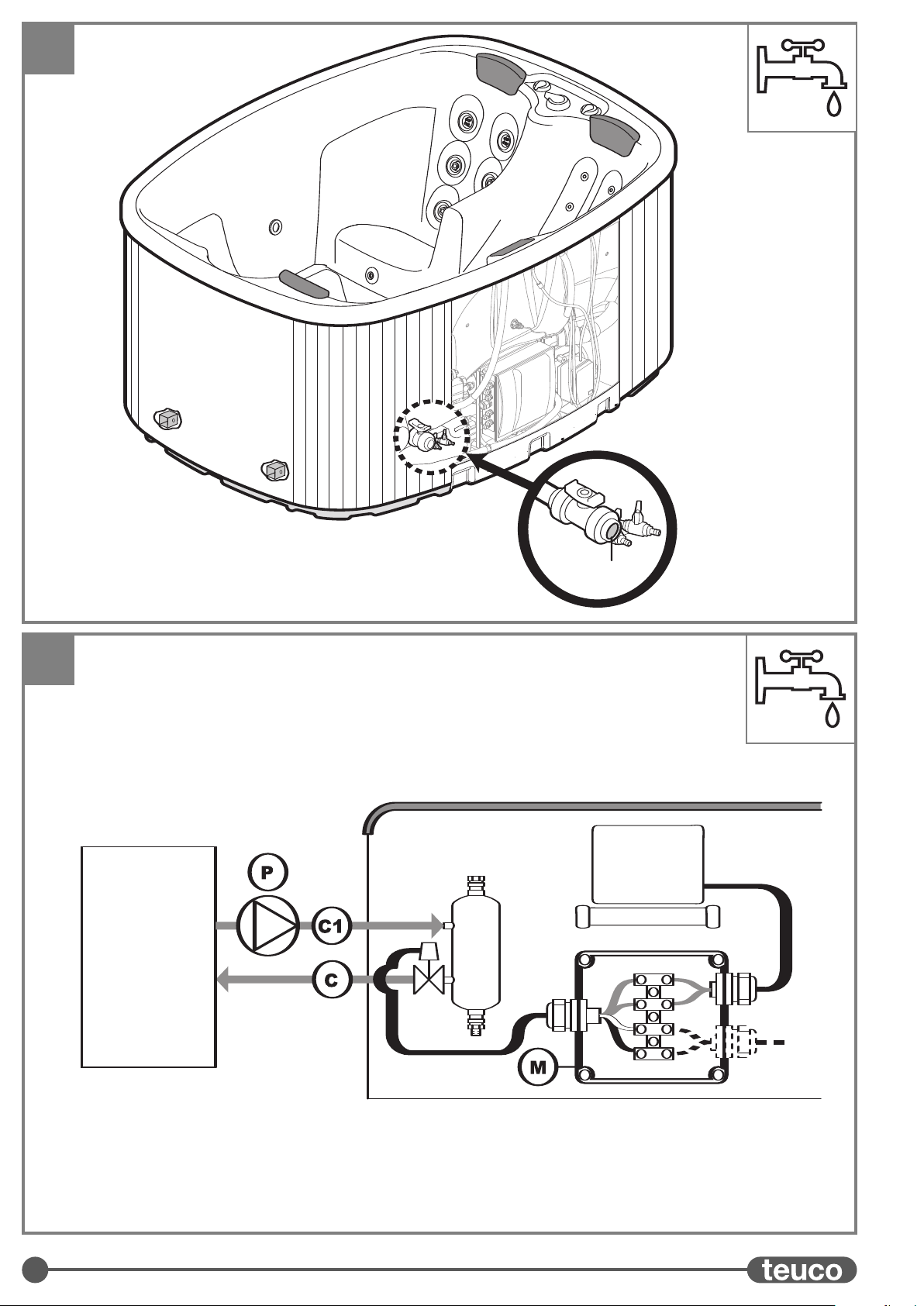
ALLACCI IDRAULICI
ALLACCIO DI SCARICO
La minipiscina Teuco é dotata di valvola di scarico con saracinesca ø 40
mm. Effettuare il collegamento della valvola con un pozzetto di scarico
(vedi preistallazione - fase 2).
ALLACCIO DI CARICO
Per il riempimento della minipiscina deve essere usato un tubo esterno (avendo
cura di non immergerlo per evitare un eventuale riflusso dell’acqua nella rete
idrica).
ALLACCIO PER SCAMBIATORE DI CALORE
La minipiscina è dotata di una scatola elettrica (M) nella quale è disponibile un
contatto "normalmente aperto pulito" (3A Max - morsetti vuoti collegati a
conduttori di colori Bianco e Nero) che può essere utilizzato per comandare
l’accensione e lo spegnimento di una caldaia, di una pompa di ricircolo, di una
valvola di zona o altro. Predisporre inoltre i tubi idraulici (Ce C1) tra caldaia e
scambiatore rispettando il verso di percorrenza dell’acqua.
ALLACCI ELETTRICI
Effettuare il collegamento alla rete elettrica nella scatola (D) predisposta sulla
minipiscina.
Il collegamento elettrico deve essere effettuato nel rispetto delle normative
come descritto nella preistallazione (fase 2).
Le dimensioni del cavo di alimentazione e del relativo passacavo vanno scelte in
base alla corrente assorbita, alla distanza dalla centralina di derivazione e al
tipo di posa.
La foratura della scatola, la scelta del pressacavo IPX5 e il montaggio sono a
carico dell’istallatore.
Effettuati tutti i collegamenti verificare il buon funzionamento dell’impianto
(vedi manuale d’uso - PRIMO AVVIAMENTO).
ATTENZIONE: DARE TENSIONE ALL’IMPIANTO SOLO DOPO AVER
RIEMPITO D’ACQUA LA MINIPISCINA
MONTAGGIO PANNELLI IN LEGNO (Art. 627)
Agganciare le parti superiori del pannello negli appositi ganci posizionati
sul telaio (A).
Posizionare i pannelli sotto il bordo della minipiscina (B).
Fissare i pannelli alla minipiscina con le apposite viti in dotazione (C).
Per il montaggio seguire l’ordine numerico.
MONTAGGIO DEI PROFILI
Inserire i profili di protezione tra il bordo e la pannellatura della
minipiscina.
11
10
9
CARATTERISTICHE SCAMBIATORE DI CALORE
Potenza minima caldaia .............................................7 Kw
Portata massima pompa di ricircolo (P) ....................1600 l/h
Prevalenza minima pompa di ricircolo (P)...............1,8 m.c.a.
Temperatura massima acqua caldaia ............................80°C
Attacchi tubi caldaia ....................................................3/4"
8
7
6B
6A
5B
5A
4
3
ISTRUZIONI DI MONTAGGIO Art. 626-627 IT
Il prodotto, per il riconoscimento della garanzia, deve essere installato così come fornito da Teuco.
Devono essere rispettate le istruzioni di montaggio, nonché i materiali consigliati e gli accessori forniti con il prodotto.
L’istallazione elettrica deve essere eseguita nel rispetto delle vigenti norme di sicurezza Nazionali come
descritto nella preistallazione.
Questo manuale é parte integrante del prodotto pertanto deve essere conservato per eventuali consultazioni future.
I dati e le caratteristiche indicate non impegnano la Teuco Guzzini Spa, che si riserva il diritto di apportare tutte le modifiche ritenute
opportune senza obbligo di preavviso o sostituzione.
Questo prodotto è destinato ad uso residenziale. In caso di utilizzo pubblico si deve garantire, oltre alle prescrizioni tecniche e di
sicurezza previste da Teuco, il pieno rispetto delle norme legislative specifiche per l’ impiantistica, la sicurezza ed il trattamento
dell’acqua vigenti nel paese dove la minipiscina Teuco viene istallata.
AVVERTENZE
14
PRE-INSTALLATION Art. 626-627
GB
ART. 626 - BUILT-IN MINIPOOL
PREPARING THE PIT
The pit for the built-in minipool should be cast in concrete,
observing the dimensions indicated in the drawing and making
certain that the structure is perfectly level.
The plinth or slab directly supporting the minipool must have a
load-bearing capacity of 633 kg/m2.
Leave a gap (A) at least 40 cm wide on all sides of the
minipool, and 70 cm at the area marked (B), to ensure sufficient
freedom of access to the plumbing and electrical equipment
installed beneath the tub.
The gap must be covered with a removable surround carried on
suitably sturdy supports; the surround must have openings of at
least 0.3 m2overall so that the pit will be adequately ventilated.
The areas of the surround bordering on the four corners of the
minipool (see H) must be equipped with anchorages for securing
the canvas (see drawing).
Provide gulleys and a drain outlet (S) at the bottom of the pit so
that water will not collect and stagnate.
ART. 627 -
PANELLED MINIPOOL
PREPARING THE PLINTH
The plinth or slab directly supporting the minipool must have a
load-bearing capacity of 643 kg/m2.
Make certain the supporting surface is perfectly level.
If the minipool is installed in the open (e.g. on a lawn), prepare
the plinth or slab with a suitably solid foundation that will ensure
the requisite stability.
PERMANENT CONNECTION OPTIONS
PLUMBING CONNECTIONS
O - ø 40 mm drain outlet connection
(for fixed installation only - optional)
C-Heat exchanger (to boiler) 3/4”
C1 - Heat exchanger (from boiler) 3/4”
- Cable outlet for connection to A.C. supply
N.B. Connections (C) and (C1) are provided only if the
minipool has a heat exchanger.
EMPTYING
The Teuco minipool has a foot valve with ø 40 mm connection.
The tub can be emptied simply by connecting a hose to the
valve, or alternatively, by making a permanent connection to the
main drain (O). In this instance it will be advisable to install a
trap with valve, which will serve as the foot valve.
IMPORTANT: before making any permanent connection to
the main drain, contact the local authorities to check on
regulations governing the disposal of chemically treated
water.
FILLING
The recommended method of filling the Teuco minipool is to
use a hose, taking care not to immerse the end as this could
allow water to flow back into the main.
IMPORTANT: if the intention is to connect the minipool
permanently to the water supply, suitable non-return
devices must be incorporated to prevent reflux back to the
water main.
Contact the local authorities before proceeding with this
type of installation.
ELECTRICAL CONNECTIONS
The electrical power supply must be in compliance with
statutory regulations for the country of installation.
The appliance must be connected to the power supply by way
of an isolating switch with minimum contact separation of 3
mm, sited away from areas 0, 1 and 2 (IEC 364-7-701).
Make certain the appliance is connected to the power source
by way of a residual current device with minimum threshold
30mA.
The connection must include a connection to the earth system
and must be:
- permanent
- able to handle the rated current (see data plate)
- specified to liquids ingress protection category IPX5
The appliance must be equipotentially bonded by making the
connection to the terminal ( ) positioned on the metal
frame.
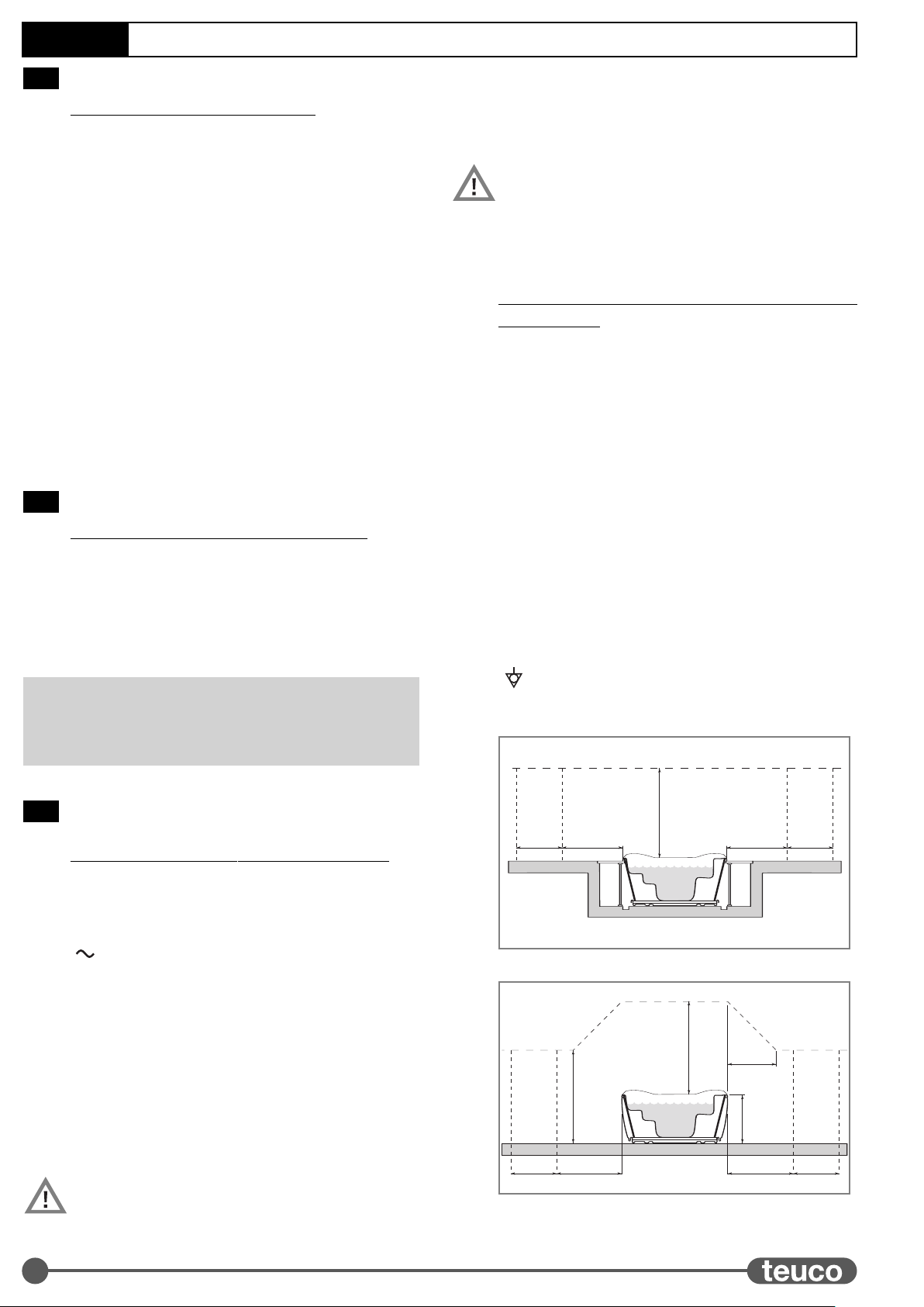
BUILT-IN MINIPOOL (IEC 364-7-701)
PANELLED MINIPOOL (IEC 364-7-701)
2,5 m
2 m1,5 m 2 m 1,5 m
ZONA 2 ZONA 2
ZONA 1
ZONA 0
ZONA 0
2,5 m
h
= h
2,5 m
2 m
1,5 m 2 m 1,5 m
ZONA 2 ZONA 2ZONA 1
ZONA 0
ZONA 0
2
ROOM VENTILATION
If the minipool is installed indoors, the room or enclosure must be
properly ventilated.
1B
1A
15
OPENING THE PACKING
Remove the crate and packing, leaving the minipool on the pallet.
Whatever transport and handling operations are involved, use only
the pallet on which the minipool is packed for shipment.
REMOVING THE COVER
Remove the cover (art. 627 only: unhook the retaining straps at the four
corners).
The cover is not intended to carry weights.
Do not sit, step or lie on the cover.
Do not place objects on the cover.
The canvas can be dangerous if not secured or properly closed.
Failure to follow the instructions for securing the canvas can result
in danger to the user.
Remove the canvas completely before stepping into the pool,
otherwise there is a risk of being trapped.
REMOVING THE PROFILES
Remove the protective profiles located between the panelling and the
edge of the minipool.
REMOVING WOOD PANELS
Unscrew the screws (A) at the base of the panels and pull the panels
towards you (B) so that they come away from their seating.
Lift the panel until the top sections are released (C) then remove each
panel from the structure securing it in place in numerical order.
FITTING THE LIFTING BARS
Insert the lifting bars into the sides of the frame and secure them with
the special screws and nuts.
NEVER LIFT THE MINIPOOL BY THE RIM OR BY THE PIPELINES.
THE MINIPOOL MUST NEVER BE LIFTED WHEN FULL OF WATER.
PLACEMENT
When lifting and placing the minipool, use slings of suitable load
capacity at least 4 metres in length (distance from the bars on the
minipool frame to the lift hook).
Slip the slings over the bars (B) and proceed to lift the minipool, then
place it on the selected site (the weight of the minipool when empty is
approximately 350 kg).
Remove the bars (B) and keep handy for future use, if needed.
PLUMBING CONNECTIONS
DRAIN CONNECTION
The Teuco minipool has a gate type drain valve with a
ø 40 mm connection.
Connect the valve to the main drain by way of a trap (see preinstallation
data sheet - step 2).
FILL CONNECTION
The recommended method of filling the Teuco minipool is to use a hose
(taking care not to immerse the end as this could cause a reflux of water
back into the main).
HEAT EXCHANGER CONNECTIONS
The minipool is provided with a switch box (M) containing a relay with a
"normally open voltage-free" contact (3A Max - spare terminals
connected to Black and White conductors) that can be used as an
on/off switch control for a boiler, a recirculation pump, a zone valve or
other appliance/component. The electrical connection to the box must
be permanent, able to handle the rated current, and specified to liquids
ingress protection category IPX5. Install the pipes (Cand C1) carrying
water to and from the boiler as indicated.
ELECTRICAL CONNECTIONS
Make the connection to the A.C. power supply at the terminal box (D)
provided on the minipool.
Electrical connections must be made in compliance with safety
regulations, as indicated in the preinstallation data sheet (step 2).
The size of the power cable and the relative clamp must be selected
according to the current load, the distance from the junction box and the
way the cable is laid and routed.
The jobs of drilling the terminal box and selecting and fitting the IPX5
clamp are the responsibility of the installer.
Having made all the connections, check that the system operates
correctly (see user manual - STARTING UP FIRST TIME).
CAUTION: POWER UP THE ELECTRICAL EQUIPMENT ONLY
AFTER THE MINIPOOL HAS BEEN FILLED WITH WATER.
FITTING WOOD PANELS (Art. 627)
Hook the top part of the panel into the special hooks on the frame (A).
Place the panels below the rim of the minipool (B).
Fix the panels to the minipool using the special screws supplied (C).
Fit the panels in numerical order.
FITTING THE PROFILES
Insert the protective profiles between the panelling and the edge of the minipool.
11
10
9
HEAT EXCHANGER SPECIFICATIONS
Minimum output of boiler ..........................................7 Kw
Maximum flow of recirculation pump (P)...................1600 l/h
Minimum head of recirculation pump (P)................1.8 m.c.a.
Max water temperature in boiler...................................80°C
Boiler pipe connections ...............................................3/4"
8
7
6B
6A
5b
5a
4
3
INSTRUCTIONS FOR INSTALLATION Art. 626-627 GB
The product must be installed exactly as supplied by Teuco, otherwise the warranty will be invalidated.
The directions for installation must be observed to the letter, as must those concerning recommended materials and the accessories
supplied with the product.
Electrical connections must be carried out in compliance with national safety regulations, as indicated in the preinstallation data sheet.
This manual constitutes an integral part of the product and must be kept for future reference.
Data and specifications indicated are not binding to the company:Teuco Guzzini SpA reserves the right to make such changes as are
deemed appropriate without prior notice and without any obligation to update.
This product is intended for home use. In the event of a Teuco minipool being commissioned for public use, procurement managers
must ensure compliance with all statutory regulations governing safety, water treatment and utility systems normally in force in the
country of installation.
WARNINGS
16
PREINSTALLATION Art. 626-627
ART. 626 - MINIPISCINE ENCASTRÉE
PRÉPARATION DU LOGEMENT
Réaliser le logement pour l’installation de la minipiscine en
béton en respectant les dimensions indiquées sur le dessin et
en ayant soin de bien le niveler.
La base d’appui de la minipiscine doit pouvoir supporter
633 kg/m2.
Prévoir un couloir (A) de 40 cm de large minimum sur tout le
périmètre et de 70 cm dans la zone (B) de la minipiscine pour
accéder aux circuits hydraulique et électrique installés sous la
minipiscine.
Recouvrir ce couloir d’un plancher amovible soutenu par des
supports adéquats; le plancher doit assurer une bonne aération
du couloir grâce à des ouvertures de 0,3 m2minimum. Prévoir
des ancrages pour la couverture (voir dessin) aux coins de la
Minipiscine (zones H) directement sur le plancher.
Réaliser un système de récupération et d’évacuation (S) sur le
fond du logement pour éviter toute stagnation d’eau.
ART. 627 -
MINIPISCINE HABILLÉE
PRÉPARATION DE LA BASE D’APPUI
Réaliser la base d’appui de la minipiscine pour une portée de
643 kg/m2.
S’assurer que la base d’appui est nivelée correctement.
Si la minipiscine est installée à l’extérieur (par exemple sur une
pelouse), réaliser la base d’appui avec un fond stabilisé qui
garantira sa stabilité.
PRÉPARATION DES RACCORDEMENTS
PRÉPARATION DES RACCORDEMENTS
HYDRAULIQUES
O- Raccord d’évacuation ø 40 mm
(pour installation fixe uniquement - facultatif)
C- Raccord pou échangeur de chaleur (à la chaudière) 3/4”
C1 - Raccord pour échangeur de chaleur (depuis la chaudière) 3/4”
- Point de sortie du câble pour connexion électrique
N.B. Les raccords (C) et (C1) sont prévus uniquement si la
minipiscine est équipée d’un échangeur de chaleur.
VIDANGE
La minipiscine Teuco est équipée d’une valve de fond avec
raccord ø 40 mm. Pour l’évacuation, relier un tuyau flexible à la
valve ou réaliser un raccordement fixe avec le conduit de
vidange (O). Dans ce cas, il est conseillé de prévoir un puisard
muni d’une valve à utiliser comme valve de fond pour faciliter la
vidange.
ATTENTION : Avant d’installer le puisard de vidange,
demander aux autorités locales quelles sont les normes
qui règlent l’évacuation de l’eau ayant subi un traitement
chimique.
REMPLISSAGE
Pour remplir une minipiscine Teuco, il est conseillé d’utiliser un
tuyau flexible extérieur en ayant soin de ne pas le plonger pour
éviter un reflux de l’eau dans le réseau hydrique.
ATTENTION : Si la minipiscine est reliée au réseau
hydrique à travers un raccordement fixe, prévoir des
dispositifs en mesure de sauvegarder le réseau hydrique
contre les phénomènes de reflux.
S’adresser aux autorités locales avant d’effectuer ce type
d’installation.
PRÉDISPOSITION DES CONNEXIONS
ÉLECTRIQUES
L’installation électrique d’alimentation doit être conforme aux
dispositions des lois nationales.
Raccorder la minipiscine au réseau à travers un interrupteur
omnipolaire avec ouverture minimum des contacts de 3mm
installé à l’écart des zones 0,1,2 (IEC 364-7-701).
Vérifier que la minipiscine est alimentée à travers un
disjoncteur différentiel avec seuil d’intervention ≤30mA.
Le raccordement au réseau doit comprendre la connexion à la
prise de terre et doit être :
- de type fixe
- approprié à la consommation (voir données sur la
plaquette)
- avec degré de résistance à la pénétration des liquides
(IPX5).
Raccorder la minipiscine à l’ensemble équipotentiel à travers la
borne ( ) qui se trouve sur le châssis métallique.
MINIPISCINE ENCASTRÉE (IEC 364-7-701)
MINIPISCINE HABILLÉE (IEC 364-7-701)
2,5 m
2 m1,5 m 2 m 1,5 m
ZONA 2 ZONA 2
ZONA 1
ZONA 0
ZONA 0
2,5 m
h
= h
2,5 m
2 m1,5 m 2 m 1,5 m
ZONA 2 ZONA 2ZONA 1
ZONA 0
ZONA 0
2
VENTILATION DE LA PIÈCE
Si la minipiscine est installée dans une pièce fermée, prévoir une
bonne ventilation de cette dernière.
1B
1A
F
17
OUVERTURE DE L’EMBALLAGE
Sortir la minipiscine de l’emballage en la laissant sur la palette.
Pour toutes les opérations de transport, utiliser exclusivement la
palette sur laquelle est posée la minipiscine.
DÉMONTAGE DE LA COUVERTURE
Enlever la couverture (uniquement pour l'art. 627: décrocher les
courroies qui se trouvent aux quatre coins de la minipiscine).
La couverture n'est pas conçue pour supporter des poids.
Ne pas s'asseoir, marcher ou s'allonger sur la couverture.
N'y déposer aucun objet.
La bâche non fixée ou laissée ouverte peut représenter un danger.
Nous conseillons à l'utilisateur de suivre scrupuleusement les
instructions pour fixer la bâche afin de ne courir aucun risque.
Retirer la bâche avant d'entrer dans la minipiscine sous peine d'y
rester encastré.
DEMONTAGE DES PROFILS
Retirer les profils de protection placés entre le bord et les panneaux de
la micro-piscine.
DEMONTAGE DES PANNEAUX EN BOIS
Dévisser les vis (A) à la base des panneaux en les tirant vers soi (B) de
façon à ce qu’elles sortent de leur siège respectif.
Soulever le panneau pour décrocher les parties supérieures (C) de
façon à pouvoir le retirer de la structure qui le bloque en suivant l’ordre
numérique.
MONTAGE DES BARRES DE LEVAGE
Introduire les barres de soulèvement sur les côtés du châssis en les
bloquant à l’aide des vis à écrou.
NE JAMAIS SOULEVER LA MINIPISCINE EN LA SAISISSANT PAR
LE BORD OU PAR LES TUYAUX.
NE JAMAIS SOULEVER LA MINIPISCINE LORSQU'ELLE EST
PLEINE D'EAU.
INSTALLATION
Pour l'installation, utiliser des courroies d'une capacité de charge
appropriée et mesurant au moins 4 mètres de long (distance entre
barres de la minipiscine et crochet de levage).
Accrocher les courroies sur les barres (B) et soulever la minipiscine
pour l'installer à l'endroit prévu (le poids à vide de la minipiscine est de
350 kg environ). Enlever les barres (B) et les mettre de côté car elles
pourront être utiles pour d'autres manoeuvres.
RACCORDEMENTS HYDRAULIQUES
RACCORD D'ÉVACUATION
La minipiscine Teuco est équipée d'une soupape d'évacuation avec
volet ø 40 mm. Raccorder la soupape à un puisard d'évacuation (voir
pré-installation - phase 2).
RACCORD DE REMPLISSAGE
Pour remplir la minipiscine, il est conseillé d'utiliser un tuyau extérieur
(en ayant soin de ne pas le plonger pour éviter un reflux de l'eau dans le
réseau hydrique).
RACCORD POUR ÉCHANGEUR DE CHALEUR
La minipiscine est dotée d'un boîtier électrique (M) qui renferme un contact
"normalement ouvert propre" (3A maxi - bornes vides reliées aux
conducteurs blanc et noir) qui peut être utilisé pour commander l'allumage
et l'arrêt d'une chaudière, d'une pompe de recyclage, d'une vanne de zone
ou autre. Le raccordement électrique au boîtier doit être de type fixe,
approprié à la consommation, avec degré de résistance à la pénétration des
liquides IPX5. Installer également les tuyaux hydrauliques (Cet C1) entre
chaudière et échangeur en respectant le sens du flux de l'eau.
CONNEXIONS ÉLECTRIQUES
Procéder à la connexion au réseau électrique à travers le boîtier (D) qui se
trouve sur la minipiscine. Procéder à l’installation électrique conformément
aux normes décrites pour la pré-installation (phase 2).
Les dimensions du câble d'alimentation et du serre-câble correspondant
doivent respecter le courant absorbé, la distance par rapport au boîtier de
dérivation et le type de pose. Le perçage du boîtier, le choix du serre-câble
IPX5 et le montage sont à la charge de l’installateur.
Après avoir effectué tous les raccordements, vérifier que le circuit
fonctionne correctement (voir manuel d’utilisation - PREMIÈRE
MISE EN MARCHE).
ATTENTION : METTRE LE CIRCUIT SOUS TENSION UNIQUEMENT
APRÈS AVOIR REMPLI LA MINIPISCINE.
MONTAGE DES PANNEAUX EN BOIS (Art. 627)
Accrocher les parties supérieures du panneau aux crochets situés sur le
châssis (A).
Positionner les panneaux sous le bord de la mini-piscine (B).
Fixer les panneaux à la mini-piscine à l’aide des vis fournies en dotation (C).
Pour le montage, suivre l’ordre numérique.
MONTAGE DES PROFILS
Introduire les profils de protection entre le bord et les panneaux de la micro-piscine.
11
10
9
CARACTÉRISTIQUES DE L'ÉCHANGEUR DE CHALEUR
Puissance minimum chaudière ...................................7 Kw
Débit maximum pompe de recyclage (P)...................1600 l/h
Prévalence minimum pompe de recyclage (P).........1,8 m.c.a.
Température maximum eau dans la chaudière ...............80°C
Raccords tuyaux chaudière ..........................................3/4"
8
7
6B
6A
5b
5a
4
3
INSTRUCTIONS POUR LE MONTAGE Art. 626-627 F
Pour jouir de la garantie, l'appareil doit être installé tel qu'il est fourni par Teuco.
Respecter les instructions de montage, les outils conseillés et les accessoires fournis avec l'appareil.
Procéder à l’installation électrique conformément aux consignes de sécurité nationales en vigueur qui sont décrites pour la
pré-installation.
Ce manuel doit toujours accompagner l'appareil et il doit être conservé pour toute consultation future.
Les données et les caractéristiques indiquées n'engagent nullement Teuco Guzzini SpA qui se réserve le droit d'apporter toutes les
modifications qu'elle jugera nécessaires sans préavis ni remplacement.
Cet appareil est destiné à un usage domestique. En cas d'usage public, garantir, outres les prescriptions techniques et de sécurité
prévues par Teuco, le respect total des normes de loi spécifiques pour le circuit, la sécurité et le traitement de l’eau en vigueur dans le
pays où la minipiscine Teuco sera installée.
AVERTISSEMENTS
18
VORINSTALLATIONS Art. 626-627
ART.626-MINISCHWIMMBECKEN EINBAUVERSION
VORBEREITUNG FÜR DEN EINBAU
Die Einbauöffnung für die Aufnahme des Minischwimmbeckens
unter Beachtung der in der Zeichnung angegebenen Maße in Beton
ausführen und auf die perfekte Nivellierung achten.
Die Auflagefläche des Minischwimmbeckens muss eine
Tragfähigkeit von 633 Kg/m2besitzen.
Richten Sie einen Gang (A) von mindestens 40 cm Breite um
das gesamte Minischwimmbecken herum und von 70 cm im
Bereich (B) ein, damit Sie auf die unter dem
Minischwimmbecken installierte hydraulische und elektrische
Anlage zugreifen können.
Dieser Korridor ist durch abnehmbare Gitterroste zu verschließen,
die durch geeignete Träger zu stützen sind; diese Gitter müssen mit
Öffnungen von mindestens 0,3 m2eine ausreichende Lüftung des
darunter liegenden Bereichs gewährleisten. An den Eckpunkten des
Minischwimmbeckens (Zonen H) müssen an den Gittern
entsprechende Verankerungen für die Abdeckung vorgesehen
werden (siehe Zeichnung).
Auf dem Boden der Einbauöffnung ist zur Vermeidung von
Wasserstauungen ein Sammel- und Ablaufsystem (S) erforderlich.
ART.627-MINISCHWIMMBECKEN MIT PANEELEN
VORBEREITUNG DER AUFLAGEFLÄCHE
Die Auflagefläche des Minischwimmbeckens muss eine
Tragfähigkeit von 643 Kg/m2besitzen.
Es ist auf die perfekte Nivellierung der Auflagefläche zu achten.
Wird das Minischwimmbecken im Freien installiert (z. B. auf
einem Rasen), muss die Auflagefläche mit einem verfestigten
Boden ausgeführt werden, der die erforderliche Stabilität
gewährleistet.
VORBEREITUNG DER BODENANSCHLÜSSE
VORBEREITUNG DER WASSERANSCHLÜSSE
O - Ablaufanschluss ø 40 mm.
(nur bei ortsfester Installation - fakultativ)
C-
Anschluss für Wärmetauscher (zum Kessel) 3/4”
C1 -
Anschluss für Wärmetauscher (vom Kessel) 3/4”
- Kabelausgang für elektrischen Anschluss
HINWEIS. Die Anschlüsse (C) und (C1) sind nur vorgesehen,
wenn das Minischwimmbecken mit einem Wärmetauscher
ausgestattet ist.
WASSERABLAUF
Das Teuco Minischwimmbecken ist mit einem Bodenventil mit
Anschluss ø 40 mm ausgestattet. Für den Wasserablauf kann man
einen Schlauch verwenden, der an das Ventil angeschlossen wird,
oder einen festen Anschluss mit der Ablaufleitung (O) ausführen. In
diesem Fall sollte ein Schacht mit Ventil, das als Bodenventil
verwendet wird, für einen problemlosen Wasserablauf vorgesehen
werden.
ACHTUNG: Vor der Durchführung des Ablaufschachts müssen
die örtlichen Behörden bezüglich der Vorschriften zum Ablauf
von chemisch behandeltem Wasser konsultiert werden.
WASSEREINLAUF
Für das Befüllen des Teuco Minischwimmbeckens wird der
Gebrauch eines externen Schlauchs empfohlen, der nicht
eingetaucht werden darf, um einen eventuellen Rückfluss des
Wassers ins Leitungsnetz zu verhindern.
ACHTUNG: Bei einem ortsfesten Anschluss des
Minischwimmbeckens an das Wasserleitungsnetz müssen
geeignete Vorrichtungen vorgesehen werden, um den
Rückfluss in das Wasserleitungsnetz zu verhindern.
Vor der Durchführung dieser Installationsart müssen die
örtlichen Behörden konsultiert werden.
VORBEREITUNG DER ELEKTRISCHEN
ANSCHLÜSSE
Die Stromversorgungsanlage am Aufstellungsort muss den
einschlägigen nationalen Vorschriften entsprechen.
Das Produkt muss über einen außerhalb der Zonen 0,1,2
(IEC 364-7-701) angebrachten Allpolschalter mit
Mindestkontaktöffnungsabstand von 3 mm an das Stromnetz
angeschlossen werden.
Es muss überprüft werden, ob das Produkt über einen Fehlerstrom-
Schutzschalter mit Ansprechschwelle ≤30mA versorgt wird.
Der Stromanschluss ist einschließlich der Erdung auszuführen und
muss:
- ortsfest sein
- für die Stromaufnahme geeignet sein (siehe Daten des
Geräteschildes)
- gegen das Eindringen von Flüssigkeiten geschützt sein
(IPX5).
Das Produkt muss über die am Metallrahmen befindliche Klemme
() an das Potentialausgleichsystem angeschlossen werden.
MINISCHWIMMBECKEN EINBAUVERSION (IEC 364-7-701)
MINISCHWIMMBECKEN MIT PANEELEN (IEC 364-7-701)
2,5 m
2 m1,5 m 2 m 1,5 m
ZONA 2 ZONA 2
ZONA 1
ZONA 0
ZONA 0
2,5 m
h
= h
2,5 m
2 m
1,5 m 2 m 1,5 m
ZONA 2 ZONA 2ZONA 1
ZONA 0
ZONA 0
2
LÜFTUNG DES RAUMS
Erfolgt die Installation in einem geschlossenen Raum, muss für ein
geeignetes Lüftungssystem des Raums gesorgt werden.
1B
1A
D

19
ÖFFNEN DER VERPACKUNG
Entfernen Sie die Verpackung vom Minischwimmbecken und lassen Sie
es auf der Palette.
Für Transporte ausschließlich die Palette benutzen, auf der das
Minischwimmbecken aufliegt.
ABNEHMEN DER ABDECKUNG
Die Abdeckung entfernen (nur beim Modell 627: die Haltegurte an den
Ecken des Minischwimmbeckens abnehmen).
Die Abdeckung ist nicht zum Tragen von Gewicht geeignet.
Nicht auf der Abdeckung sitzen, laufen oder liegen.
Keine Gegenstände ablegen.
Eine nicht befestigte oder geschlossene Abdeckung stellt eine
potentielle Gefahr dar.
Es liegt eine Gefahr für den Benutzer vor, sollten die Anleitungen
zur Befestigung der Abdeckung nicht befolgt werden.
Entfernen Sie die Abdeckung, bevor Sie in das
Minischwimmbecken steigen; Sie könnten sich möglicherweise
darin verfangen.
ABBAU DER PROFILE
Entfernen Sie die Schutzprofile zwischen den Platten des
Minischwimmbads
ABBAU DER HOLZPANEELE
Schrauben (A) abnehmen und nach vorn ziehen (B). Damit aus den
entsprechenden Öffnungen entfernen.
Abdeckung anheben und die oberen Teile abnehmen (C), danach
gemäß den Angaben in Ziffern aus der Verankerung nehmen.
EINBAU DER HEBESTANGEN
Die Auflagestreben an den Seiten des Rahmens anbringen und mit den
Schrauben und Muttern befestigen.
DAS MINISCHWIMMBECKEN NIEMALS AM RAND ODER AN DEN
LEITUNGEN HOCHHEBEN.
DAS MINISCHWIMMBECKEN NIEMALS MIT WASSER GEFÜLLT
ANHEBEN.
AUFSTELLUNG
Für den Aufstellung Gurte mit ausreichender Tragkraft und einer Länge
von mindestens 4 Metern benutzen (Abstand zwischen den Stangen des
Minischwimmbeckens und des Hubhakens).
Die Gurte an den Stangen (B) anbringen, das Minischwimmbecken anheben
und an den gewünschten Ort stellen (das Leergewicht des
Minischwimmbeckens liegt bei etwa 350 kg).
Die Stangen (B) abnehmen und für einen eventuellen zukünftigen Gebrauch zur
Seite legen.
WASSERANSCHLÜSSE
ABLAUFANSCHLUSS
Das Teuco Minischwimmbecken verfügt über ein Ablaufventil mit
Absperrschieber mit einem Durchmesser von ø 40 mm.
Den Anschluss des Ventils mit einem Ablaufschacht durchführen (siehe
Vorinstallation - Schritt 2).
EINLAUFANSCHLUSS
Für das Befüllen des Minischwimmbeckens muss ein externer Schlauch benutzt
werden, der nicht eingetaucht werden darf, um einen etwaigen Rückfluss des
Wassers ins Leitungsnetz zu verhindern.
ANSCHLUSS FÜR WÄRMETAUSCHER
Das Minischwimmbecken ist mit einem Schaltkasten (M) ausgestattet, in dem
der verfügbare potentialfreie Arbeitskontakt (3A Max - freie und an weiße sowie
schwarze Leiter angeschlossene Klemmen) für die Ein-/Abschaltung eines
Kessels, einer Umlaufpumpe, eines Bereichsventils usw. verwendet werden
kann. Der elektrische Anschluss an den Schaltkasten muss ortsfest, unter
Berücksichtigung der Stromaufnahme und mit Schutzart IPX5 gegen das
Eindringen von Flüssigkeiten ausgeführt werden. Bereiten Sie weiterhin die
Wasserrohre (Cund C1) zwischen Kessel und Wärmetauscher unter
Berücksichtigung der Wasserflussrichtung vor.
ELEKTRISCHEANSCHLÜSSE
Den Stromanschluss in dem am Minischwimmbecken vorhandenen
Schaltkasten (D) ausführen. Der Stromanschluss muss unter Beachtung der
Vorschriften gemäß der Vorinstallation (Schritt 2) ausgeführt werden.
Die Abmessungen des Stromkabels und der passenden Kabelführung werden
auf Basis der aufgenommenen Spannung , des Abstands vom Verteilerkasten
und der Verlegungsart ausgewählt. Das Bohren des Schaltkastens, die Wahl der
Kabelverschraubung IPX5 und der Einbau gehen zu Lasten des Installateurs.
Nach Ausführung aller Anschlüsse ist der einwandfreie Betrieb der Anlage
zu überprüfen (siehe Handbuch - ERSTMALIGE INBETRIEBNAHME).
ACHTUNG: DEN STROM NUR NACH FÜLLEN DES
MINISCHWIMMBECKENS MIT WASSER EINSCHALTEN.
MONTAGE DER HOLZPANEELE (Art. 627)
Die oberen Teile des Paneels in die Verankerungen auf dem Rahmen einhaken (A).
Die Paneele unter dem Rand des Minischwimmbeckens (B) anbringen.
Die Paneele an dem Minischwimmbecken mit den gelieferten Schrauben (C)
befestigen.
Die angegebene Reihenfolge zur Montage beachten.
ANBAU DER PROFILE
Setzen Sie die Schutzprofile zwischen den Platten des
Minischwimmbads und dessen Rand ein.
11
10
9
TECHNISCHE DATEN WÄRMETAUSCHER
Mindestleistung Kessel .............................................7 Kw
Max. Förderleistung Umlaufpumpe (P)......................1600 l/h
Min. Förderhöhe Umlaufpumpe (P) ........................1,8 m.c.a.
Max. Wassertemperatur Kessel ....................................80°C
Rohranschlüsse Kessel................................................3/4"
8
7
6B
6A
5b
5a
4
3
MONTAGEANLEITUNGEN Art. 626-627 D
Zur Gültigkeit der Garantie muss das Produkt wie vonTeuco geliefert installiert werden.
Achten Sie auf die Montageanleitungen sowie die Materialempfehlungen und die mit dem Produkt gelieferten Zubehörteile.
Bei der elektrischen Installation beachten Sie die gültigen nationalen Sicherheitsvorschriften gemäß Vorinstallation.
Bewahren Sie diese Bedienungs- und Wartungsanleitung sorgfältig auf, da sie wichtiger Bestandteil der Anlage ist und als Nachschlagewerk
dient.
Die angegebenen Daten und Produkteigenschaften sind nicht verbindlich. Teuco Guzzini SpA behält sich das Recht vor, ohne
Vorankündigung alle für nötig erachteten Änderungen vorzunehmen, ohne dass sich hieraus Ersatzansprüche ableiten lassen.
Dieses Produkt ist für den Hausgebrauch gedacht. Bei öffentlichem Gebrauch muss neben den von Teuco vorgesehenen technischen und
Sicherheitsvorschriften die uneingeschränkte Beachtung der speziellen gesetzlichen Normen für die Anlage, die Sicherheit und die
Behandlung des Wassers in den jeweiligen Installationsländern des Minischwimmbeckens vonTeuco garantiert werden.
HINWEISE
20
PREINSTALACIÓN Art. 626-627
ART. 626 - MINIPISCINA PARA ENCASTRAR
TRABAJOS PRELIMINARES
La medidas que debe tener la piscina de hormigón en la que se
encastrará la minipiscina están indicadas en la figura. La
superficie debe estar perfectamente a nivel.
La losa en que se apoya la minipiscina debe ser capaz de
soportar una carga mínima de 633 kg/m2.
Dejar una luz mínima (A) de 40 cm de anchura por todo el
perímetro y de 70 cm de anchura en la zona de la minipiscina
para garantizar el acceso a los sistemas hidráulico y eléctrico
que están instalados debajo.
Este corredor debe cerrarse con plataformas extraíbles
convenientemente apoyadas. Para garantizar una buena
ventilación de dicho espacio en la estructura de las plataformas
debe haber aberturas de 0,3 m2 como mínimo. En los ángulos
de la minipiscina (zonas H) y sobre las plataformas deberán
prepararse los anclajes adecuados para la cubierta (ver dibujo).
En el fondo debe haber un sistema de recogida y desagüe (S)
para que el agua no se estanque.
ART. 627 -
MINIPISCINA CON PANELES
PREPARACIÓN DE LA BASE DE APOYO
La superficie de apoyo de la minipiscina debe ser capaz de
soportar una carga mínima de 643 kg/m2.
Además debe estar perfectamente nivelada.
Si la piscina se instala fuera de la vivienda (por ejemplo, en el
jardín) es importante construir una base de apoyo con un fondo
perfectamente estabilizado.
EMPALMES DEL FONDO
ACOMETIDA A LA RED DE AGUA
O- Empalme para desagüe ø 40 mm
(sólo para instalación fija - facultativa)
C- Conexión intercambiador de calor (a la caldera) 3/4"
C1 - Conexión para intercambiador de calor (desde la
caldera) 3/4"
- Punto de salida del cable para la conexión eléctrica
Nota: las conexiones (C) y (C1) se han previsto únicamente
cuando la minipiscina viene equipada con cambiador de
calor.
DESAGÜE
La minipiscina Teuco cuenta con una válvula de fondo con
empalme de ø 40 mm. Para el desagüe se puede conectar a
ella un tubo flexible o construir una conexión fija con la tubería
de desagüe (O). En el segundo caso se recomienda preparar
una arqueta con una válvula que hará las veces de válvula de
fondo.
ATENCIÓN: Antes de instalar la arqueta consulte las
normas municipales que reglamentan el manejo de agua
tratada químicamente.
LLENADO
Para llenar la minipiscina se aconseja utilizar un tubo flexible
externo. Es preferible no sumergirlo para evitar el reflujo del
agua.
ATENCIÓN: Si se prefiere hacer una conexión fija a la red
de aguas también es necesario adoptar medidas
adecuadas para evitar el reflujo.
Consultar los reglamentos municipales antes de efectuar
este tipo de instalación.
CONEXIONES ELÉCTRICAS
La instalación eléctrica debe ser conforme a las disposiciones
legales nacionales.
La minipiscina debe conectarse a la red mediante un
interruptor diferencial omnipolar con una apertura mínima de
los contactos de 3mm.
El interruptor debe estar colocado fuera de las zonas 0,1,2
(IEC 364-7-701) y debe tener un umbral de disparo de 30mA.
La red debe estar conectada a tierra. La conexión de la piscina
a la red debe ser:
- fija
- adecuada a la corriente que absorbe la minipiscina
(ver placa de datos)
- hermética a la penetración de líquidos (IPX5).
La minipiscina debe conectarse al grupo equipotencial
mediante la regleta ( ) del bastidor metálico.
MINIPISCINA PARA ENCASTRAR
(IEC 364-7-701)
MINIPISCINA CON PANELES (IEC 364-7-701)
2,5 m
2 m1,5 m 2 m 1,5 m
ZONA 2 ZONA 2
ZONA 1
ZONA 0
ZONA 0
2,5 m
h
= h
2,5 m
2 m1,5 m 2 m 1,5 m
ZONA 2 ZONA 2ZONA 1
ZONA 0
ZONA 0
2
VENTILACIÓN DEL AMBIENTE
Si la minipiscina se instala bajo techo es preciso asegurar a la
estancia una buena ventilación.
1B
1A
E
This manual suits for next models
4
Table of contents
Languages:
Other Teuco Hot Tub manuals


Popular Hot Tub manuals by other brands


 owner's manual")


CalderaSpas
CalderaSpas CalderaSpas Utopia Series owner's manual

anko
anko SS-601A user manual

CalderaSpas
CalderaSpas CANTABRIA owner's manual

Dimension One Spas
Dimension One Spas HYDRO SPORT Installation and owner's guide

Bestway
Bestway Lay-Z-Spa Maldives HydroJet Pro manual

Dimension One Spas
Dimension One Spas Nautilus Specifications