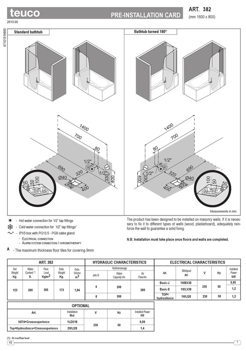
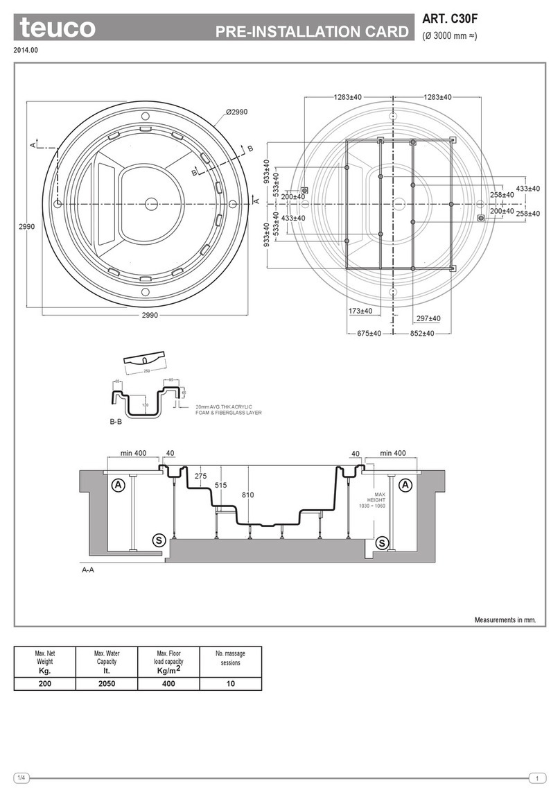
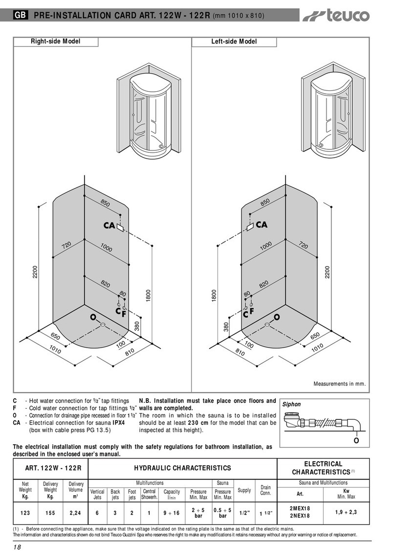
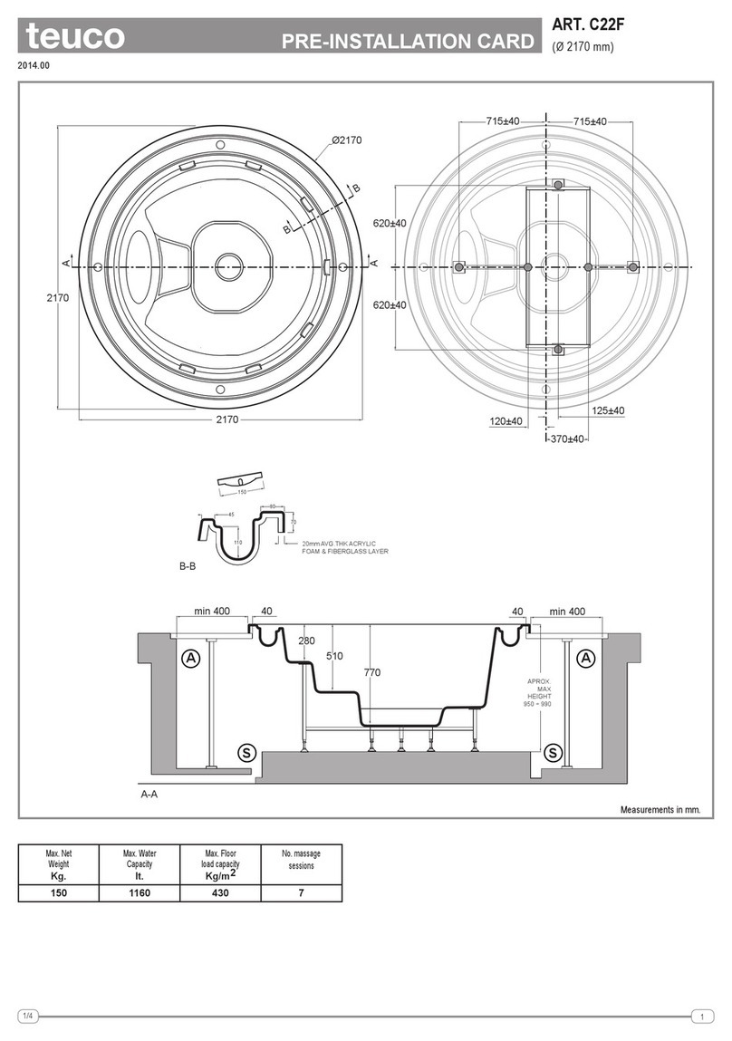
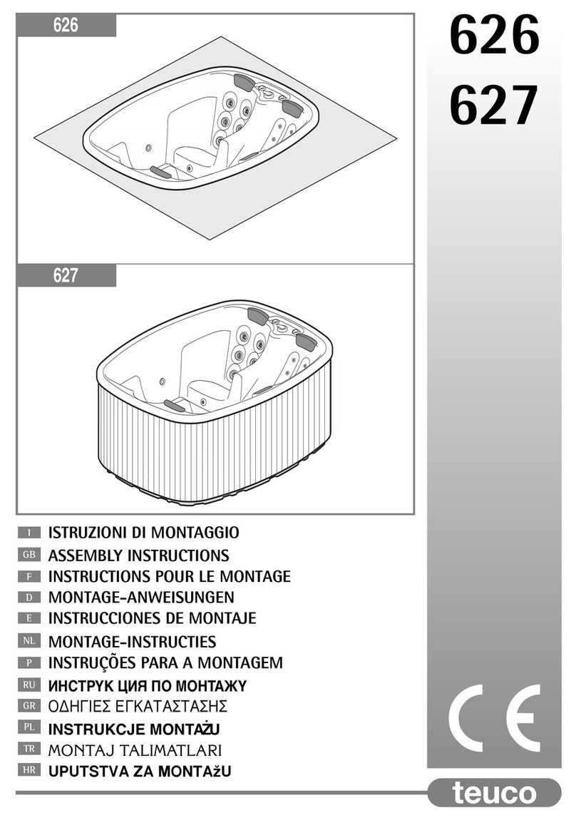
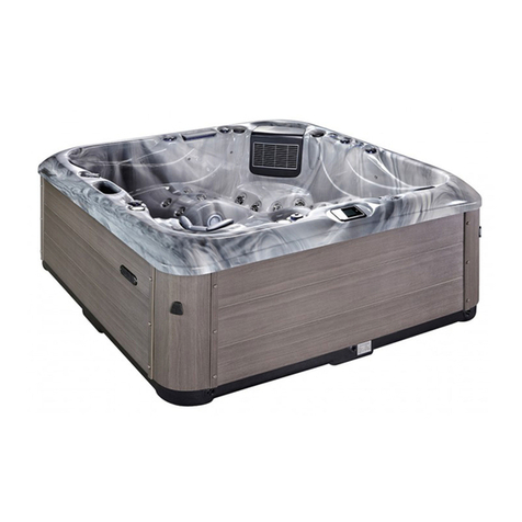
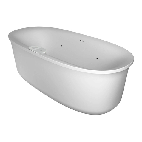
Teuco 620HU User manual

IISTRUZIONI DI MONTAGGIO
GB ASSEMBLY INSTRUCTIONS
FINSTRUCTIONS POUR LE MONTAGE
DMONTAGE-ANWEISUNGEN
EINSTRUCCIONES DE MONTAJE
NL MONTAGE-INSTRUCTIES
PINSTRUÇÕES PARA A MONTAGEM
RU
ИHCTPYK ЦИЯ ПO MOHTAЖY
GR
ΟΔΗΓΙΕΣ ΕΓΚΑΤΑΣΤΑΣΗΣ
PL INSTRUKCJE MONTAŻU
TR MONTAJ TALİMATLARI
HR UPUTSTVA ZA MONTAŽU
620HU

2
CARATTERISTICHE ELETTRICHE
(2)
• ELECTRICAL SPECIFICATIONS
(2)
• CARACTÉRISTIQUES ÉLECTRIQUES
(2)
• ELEKTRISCHE
DATEN
(2)
• CARACTERÍSTICAS ELÉCTRICAS
(2)
• ELEKTRISCHE KENMERKEN
(2)
• CARACTERÍSTICAS ELÉCTRICAS(2) •
ЭЛЕКТРИЧЕСКИЕ ХАРАКТЕРИСТИКИ(2) • ΗΛΕΚΤΡΙΚΑ ΧΑΡΑΚΤΗΡΙΣΤΙΚΑ
(2)
• CHARAKTERYSTYKI ELEKTRYCZNE
(2)
•
ELEKTRİKSEL KARAKTERİSTİKLER
(2)
• ELEKTRIČNI PODACI
(2)
I
Leggere le AVVERTENZE e le istruzioni
descritte in questo manuale.
GB
Read the WARNINGS and the instructions
described in this manual.
F
Lire les AVERTISSEMENTS et les instructions
contenus dans ce manuel.
D
Lesen Sie die HINWEISE und die Anleitungen
in diesem Handbuch.
E
Leer las ADVERTENCIAS y las instrucciones
que contiene este manual.
NL
Lees de RICHTLIJNEN en de instructies
uit deze handleiding door.
P
Leia as ADVERTÊNCIAS e as instruções
descritas neste manual.
RU
Внимательно прочитайте содержащиеся
внастоящем руководстве
ПРАВИЛА
и
инструкции.
GR
Διαβάστε τις ΠΡΟΕΙΔΟΠΟΙΗΣΕΙΣ και τις
οδηγίες του παρόντος εγχειριδίου.
PL
Zapoznaćsięz OSTRZEŻENIAMI i
instrukcjami podanymi w niniejszym
podręczniku.
TR
Bu kitapçιkta açιklanmakta olan
UYARILAR ve talimatlarιdikkatlice
okuyunuz
HR
Pročitajte NAPOMENE i savjete
navedene u ovim uputstvima
Peso netto
Net weight
Poids net
Nettogewicht
Peso neto
Netto gewicht
Peso líquido
Вес нетто
Καθαρό βάρος
Ciężar netto
Net ağιrlιk
Neto težina
225 kg
ART.
620HU
Carico sul pavimento
Floor load
Charge au sol
Bodenbelast
Carga al pavimiento
Belasting op de vloer
Carga sobre pavimento
Нагрузка на полу
Βάρος στο δάπεδο
Obciążenie podłoża
Zemin yükü
Opterećenje poda
440 kg/m2
Contenuto acqua
Water capacity
Contenance eau
Wasserinhalt
Volumen de agua
Waterinhoud
Conteúdo água
Количество воды
Χωρητικότη-τα νερού
Pojemność wody
Su Kapasitesi
Nosivost vode
1100 lt.
Peso di spedizione
Shipping weight
Poids emballage compris
Versandgewicht
Peso de expedición
Verzendgewicht
Peso expedição
Вес упакованного изделия
Βάρος αποστολής
Ciężar podczas transportu
Nakliye ağιrlιğι
Težina pošiljke
479 kg
Volume di spedizione
Shipping volume
Cubage
Versandvolumen
Volumen de expedición
Verzend-volume
Volume expedição
Объем упаковки
Όγκος αποστολής˜
Objętość podczas transportu
Nakliye Hacmi
Zapremnina ambalaže
8,36 m3
44 kg
Spa-pack 150 kg/m2
- 48 kg 0,35 m3
Modello
Model
Modèle
Modell
Modelo
Model
Modelo
Модель
Μοντέλο
Model
Model
Model
VHz
230 50
Assorbimento pompe idromassaggio (2 pompe) più faretto
Absorbed power for spa system pump (2 pumps) plus spotlight
Absorption pompes hydromassage (2 pompes) + spot
Stromaufnahme Whirlpool- Pumpen (2 Pumpen) plus Strahler
Absorción bombas hidromasaje (2 bombas) más faro
Opname hydromassagepompen (2pompen) plus lampje
Absorção das bombas de hidromassagem (2 bombas) mais foco de luz
Потребляемая мощность гидромассажных насосов (2 насоса) иподсветки
Κατανάλωση αντλιών υδρομασάζ (2 αντλίες) συν φως πισίνας
Zapotrzebowanie pomp do hydromasażu (2 pompy) plus lampka
Hidromasaj pompasısarfiyatı(2 pompa) artıspot
Apsorpcija pumpi za hidromasažu (2 pumpe) plus reflektor
4500
kW
4WST28
(2) - Prima di collegare il prodotto accertarsi che i dati di targa siano rispondenti a quelli della rete di distribuzione elettrica
(2) - Before making any electrical connections, check that the rated voltage and current of the appliance are matched to the mains power supply.
(2) - Avant de raccorder l’hydrodouche, s’assurer que les données de la plaquette correspondent aux données du réseau de distribution électrique.
(2) - Überprüfen Sie vor dem Stromanschluß die Entsprechung von Schild- und Netzwerten
(2) - Antes de conectar el producto a la red de electricidad hay que comprobar si las características de la misma coinciden con las que figuran en la placa de datos del producto.
(2) - Alvorens het product aan te sluiten, dient u zich ervan te verzekeren dat de gegevens op het typeplaa je overeenstemmen met de kenmerken van het elektrische voedingsnet.
(2) - Antes de ligar o produto, certifique-se de que os dados da chapa de características correspondem aos da rede de distribuição eléctrica.
(2) - Прежде чем выполнить электрические соединения проверьте соответствие указанных на табличке изделия номинальных
данных схарактеристиками сети электроснабжения.
(2) - Πριν συνδέσετε το προϊόν, βεβαιωθείτε ότι τα χαρακτηριστικά της πινακίδας αντιστοιχούν σε εκείνα του ηλεκτρικού δικτύου.
(2) - Przed wykonaniem podłączeńelektrycznych należy sprawdzićczy dane znamionowe urządzenia sąodpowienie dla elektrycznej instalacji zasilającej.
(2) - Herhangi bir elektrik bağlantιsιyapmadan önce cihazιn nominal voltaj ve akιmιnιn ana güç hattιna eşdeğer olduğundan emin olunuz.
(2) - Prije nego što priključite uređaj provjerite da li su podaci navedeni na pločici primjereni napojnoj električnoj mreži.

3
AA
65915
SEZ. A-A
S
A A
1742
300 1450
250
2380
2320
min.400 min.400
442
746
842
529
A
890
670
470
1
Spa-pack

MAX 8m
Ø 2320
400
A
800
400 Ø63
AA
200cm Max
1310
910
SS
4
2
A
B
3A
A
PH2
3B

5
B
A
±19
3C3D
A
B
4

811
994
647 967
435
967
932
473
266
914 1029
352 352
Ø8
A B
7
7
7
6
6
x7
5

7
300 1450
250
7
8

8
1
3
2
Ø
4
5
6
7
50 mm
63 mm
63 mm
80/75 mm
9
8
5
5
6
6
6
5
6
5
7
4
7
9

9

10
10

11
M5x10
Ø5x10
M5x10
Ø5x10
L+
L
1P
2P
3P
1R
2R
3R
22
24
+/12V
+/12V
+/12V
I 1
I 2
I 6
L1
L2
L3
N

12
I- Istruzioni di Montaggio 620HU .........................................13
GB - Assembly Instructions 620HU ..........................................15
F- Instructions pour le Montage 620HU............................17
D- Montage-Anweisungen 620HU..........................................19
E- Instrucciones de Montaje 620HU.....................................21
NL - Montage-Instructies 620HU .................................................23
P- Instruções para a Montagem 620HU.............................25
RU - Инструкция по монтажу 620HU .....................................27
GR - Οδηγίες εγκατάστασης 620HU...........................................29
PL - Instrukcje montażu 620HU ...................................................31
TR - Model 620HU - Montaj Talimatlarι....................................33
HR - Uputstva za montažu 620HU...............................................35

13
ISTRUZIONI DI MONTAGGIO Art. 620HU
1
CARATTERISTICHE TECNICHE
L'articolo 620HU si compone di:
- SPA-PACK: comprendente le pompe idromassaggio e il
quadro elettrico di controllo.
- MINIPISCINA: deve essere collegata tramite tubazioni allo
Spa-pack e alla stazione filtrante e di compensazione non
fornita con il prodotto.
COMPONENTI
Si riporta di seguito la descrizione dei componenti e dei
collegamenti necessari alla realizzazione dell'impianto (fig.9).
Minipiscina e tubazioni
1) canaletta di sfioro con griglia
2) sostegni metallici perimetrali
3) collegamento alla rete idrica (eventuale)
4) adduzione acqua trattata e riscaldata
5) aspirazione idromassaggio
6) mandata idromassaggio
7) raccolta acqua dal bordo sfioratore
Spa-pack
8) quadro elettrico
9) pompe idromassaggio
2
INSTALLAZIONE
Minipiscina
La minipiscina è caratterizzata dall'installazione ad incasso, con
il bordo vasca a filo pavimento; per l'incasso fare riferimento alle
misure indicate nei disegni.
(N.B dato che vi possono essere delle lievi variazioni nelle
caratteristiche dimensionali, prima dell'installazione
verificarne le misure)
Realizzare il vano per l'alloggiamento della minipiscina in
calcestruzzo, rispettando le misure indicate nel disegno e
facendo attenzione che sia perfettamente livellato. La base di
supporto dovrà essere adeguata al carico della minipiscina
(vedi dati riportati nella tabella).
Predisporre un corridoio (A) di almeno 40cm di larghezza su
tutto il perimetro della minipiscina per garantire l’accessibilità
all’impianto idraulico ed elettrico istallati sotto la minipiscina.
Tale corridoio deve essere chiuso con pedane removibili
sorrette da adeguati sostegni; le pedane devono garantire una
sufficiente areazione del vano con aperture di almeno 0,3 m2.
Realizzare sul fondo del vano un sistema di raccolta e scarico
per evitare eventuali ristagni d'acqua (S).
Studiare i percorsi e predisporre eventuali scavi e canalette
necessari per il collegamento idraulico ed elettrico della
minipiscina con lo spa-pack e con la vasca di compenso ,
tenendo presente che le tubazioni idrauliche sono quelle
indicate (Fig. 9) e dovranno essere posizionate evitando che si
creino sifoni.
Spa pack
Lo spack-pack deve essere installato ad una distanza
inferiore a 8 metri dalla minipiscina: una lunghezza minore
delle tubazioni comporta minore perdite di carico e migliori
prestazioni complessive dell'impianto idromassaggio. In ogni
caso lo spa-pack deve essere posizionato alla stessa quota, o
più bassa di quella della vasca.
Si consiglia di evitare, per quanto possibile , le curve e si
consiglia invece l'uso di tubazioni flessibili in PVC. La tubazione
deve essere in grado di resistere alla pressione di 3 bar e alla
temperatura di 60°C.
Verificare, in caso di utilizzo di tubi flessibili, che il tubo abbia
caratteristiche idonee per resistere alla depressione generata
dall'aspirazione delle pompe.
Il dimensionamento delle condotte prescelto non deve
essere alterato, ad esempio, scegliendo, per la parte di
impianto da costruirsi in opera, diametri di tipo diverso e
raccordi per tubazioni con diametri differenti.
Le valvole poste in opera a cura dell'installatore devono essere
del tipo a sfera, con sezione di passaggio in posizione aperta
pari a quella della tubazione. In esercizio normale tutte le
valvole poste in opera, escluse ovviamente quelle eventuali di
scarico, devono essere in posizione di completa apertura.
Lo spa-pack deve essere sempre installato in ambiente chiuso,
ma areato, non accessibile alle persone senza l'uso di chiavi o
utensili e protetto dall'acqua e dalle intemperie.
Il locale che contiene lo Spa-pack non deve superare la
temperatura di 40°C.
3a
APERTURA IMBALLO
Togliere il nylon che avvolge la minipiscina.
Tagliare le fascette, rimuovere il corrimano (fig.A) e i puntoni
(fig.B).
3b
Smontare le viti che fissano la minipiscina al telaio.
3c
Posizionare orizzontalmente la minipiscina (fig.A) rimuovere i
bulloni che fissano la piscina al telaio (fig.B).
3d
Togliere il telaio e il cartone di protezione.
4
COLLEGAMENTO DISTRIBUTORE
Fissare il distributore al bocchettone mediante l’apposita ghiera.
5
POSIZIONAMENTO IN OPERA
Inserire la minipiscina nel luogo di installazione, disponendola in
modo che gli attacchi idraulici siano rivolti verso il canale delle
condotte.
Rimontare le aste con piedini tolte in precedenza.
IT
Il prodotto, per il riconoscimento della garanzia, deve essere installato così come fornito da Teuco.
Devono essere rispettate le istruzioni di montaggio, nonché i materiali consigliati e gli accessori forniti con il prodotto.
L’istallazione elettrica deve essere eseguita nel rispetto delle vigenti norme di sicurezza Nazionali come descritto nella
preistallazione.
Questo manuale é parte integrante del prodotto pertanto deve essere conservato per eventuali consultazioni future.
I dati e le caratteristiche indicate non impegnano la Teuco Guzzini Spa, che si riserva il diritto di apportare tutte le
modifiche ritenute opportune senza obbligo di preavviso o sostituzione.
Questo prodotto è destinato ad uso residenziale. In caso di utilizzo intensivo si deve garantire, oltre alle prescrizioni
tecniche e di sicurezza previste da Teuco, il pieno rispetto delle norme legislative specifiche per l’ impiantistica, la
sicurezza ed il trattamento dell’acqua vigenti nel paese dove la minipiscina Teuco viene istallata.
E' responsabilità dell'installatore/proprietario verificare e attenersi a specifiche disposizioni locali prima dell'installazione.
AVVERTENZE

14
6
LIVELLAMENTO MINIPISCINA
Portare in “bolla” la piscina regolando i piedini. Fissare i piedini
al pavimento con le viti con stop in dotazione.
7
MONTAGGIO CORRIMANO
Eseguire le forature sul pavimento facendo attenzione alle
distanze indicate nel disegno.
Le viti (non fornite) devono essere viti con stop in acciaio
M8x100.
8
FISSAGGIO DELLA COPERTURA
Posizionare la copertura sulla minipiscina. In corrispondenza
delle cinghie predisporre opportuni ancoraggi (non forniti) sulla
pedana.
La copertura non è concepita per sostenere pesi.
Non sedersi, camminare o sdraiarsi sulla copertura.
Non depositarvi oggetti.
La copertura non fissata o non chiusa bene può essere
pericolosa.
Non seguire le istruzioni di fissaggio della copertura
quando la vasca viene lasciata con acqua all’interno può
costituire fonte di pericolo.
Rimuovere completamente la copertura prima di entrare
nella minipiscina; si può rimanere incastrati.
9
ALLACCI IDRAULICI
A cura dell'installatore deve essere realizzato il sistema di
tubazioni (compresi i raccordi, valvole sfera etc.) , per il
collegamento della minipiscina con lo Spa-pack e con la vasca
di compenso (non fornita) e devono essere predisposti dei
pozzetti di scarico di adeguate dimensioni ed ispezionabili per
l'eventuale pulizia, ai quali collegare lo scarico.
SCARICO: Sul fondo della piscina è posizionata una bocchetta
munita di griglia e di un tubo, diametro 50 che arriva fino alla
zona degli attacchi idraulici (tubo 6).
Deve essere utilizzata per far arrivare alla piscina acqua trattata
e riscaldata, e può essere utilizzata per collegare la piscina allo
scarico.
In zone particolarmente fredde, per evitare il rischio di
congelamento dell'acqua residua, si consiglia di installare
e costruire in sede lungo le condotte delle valvole per il
drenaggio completo dei tubi.
ATTENZIONE: Prima di predisporre il pozzetto di scarico,
consultare le autorità locali per le normative che regolano
lo scarico di acqua trattata chimicamente.
CARICO: Per il riempimento della minipiscina Teuco è
consigliato l’utilizzo di un tubo flessibile esterno, avendo cura di
non immergerlo per evitare un eventuale riflusso dell’acqua
nella rete idrica (3).
ATTENZIONE: Nel caso di collegamento fisso della
minipiscina alla rete idrica è necessaria l’adozione di
opportuni dispositivi in grado di salvaguardare la rete
idrica da fenomeni di riflusso.
Consultare le autorità locali prima di effettuare tale tipo di
istallazione.
10
ALLACCI ELETTRICI
L’impianto elettrico di alimentazione deve essere conforme
alla norma CEI 64-8.
Ai fini del dimensionamento dello stesso, si precisa che gli
assorbimenti max. riportati nella tabella “caratteristiche
elettriche”, vanno intesi come potenze nominali assorbite
durante il funzionamento.
Il collegamento alla rete dovrà essere di tipo fisso.
Il prodotto deve essere collegato alla rete attraverso un
interruttore onnipolare
(I)
, con apertura dei contatti che
garantisca la disconnessione completa nelle condizioni
della categoria di sovratenzione III (3 mm minimo),
posizionato al di fuori delle zone 0,1,2 (CEI 64-8/7).
Verificare che il prodotto sia alimentato attraverso un
interruttore differenziale con soglia di intervento =30mA.
Il prodotto deve essere collegato all’insieme equipotenziale
tramite l’apposito morsetto ( ) posizionato sul basamento
dello Spa-pack in vicinanza di una pompa.
2,5 m
2 m1,5 m 2 m 1,5 m
ZONA 2 ZONA 2ZONA 1
ZONA 0
ZONA 0
Per alimentare il quadro elettrico dello spa-pack si dovrà
utilizzare un cavo tripolare di caratteristiche adeguate
all'impiego, sfruttando il pressacavo appositamente
predisposto sul quadro stesso.
Il collegamento dovrà essere fatto utilizzando i morsetti del
sezionatore e la barra di terra posti all'interno del quadro
(fig.10).
Si dovrà poi provvedere al collegamento del faretto della
piscina (12V-2A), per la cui alimentazione sarà necessario
utilizzare un cavo (non fornito) 2 x 1,5 H05VV-F.
Effettuare il collegamento al quadro tramite i morsetti N. 22
e 24 sfruttando l'apposito pressacavo PG 13.5, ed al faro
tramite l'apposita morsettiera in dotazione (fig. 10).
Per la messa a terra dello stesso utilizzare un idoneo cavo
giallo-verde (non fornito), collegandone le due estremità
rispettivamente alla barra di terra all'interno del quadro
(pressacavo PG 7 disponibile), ed all'apposita vite sul
corpo del faretto (fig 10).
In entrambe le connessioni avere cura di utilizzare
opportuni terminali d'estremità e rondelle dentate
antiallentamento.
Utilizzare l'apposito morsetto posizionato sul basamento
dello spa-pack per effettuare il collegamento dello stesso
all'insieme equipotenziale dell'edificio.

15
INSTRUCTIONS FOR INSTALLATION Art. 620HU
1
TECHNICAL SPECIFICATIONS
The 620HU pool comprises:
-SPA-PACK: includes the whirlpool pumps and the
electrical equipment panel.
-MINIPOOL: the actual pool must be connected by
pipelines to the Spa-pack, and to the filtration unit and
overflow tank (not supplied with the 620HU).
COMPONENTS
Indicated below are the various components and
connections needed for installation of the system (fig. 9).
Minipool and pipelines
1) spill edge gutter and grating
2) metal legs
3) connections to water main (if applicable)
4) filtered and heated water inlet
5) whirlpool pump suction
6) whirlpool pump delivery
7) collection of water from spill edge
Spa-pack
8) electrical panel
9) whirlpool pumps
2
INSTALLATION
Minipool
The minipool is designed specifically for built-in type
installation, with the edge exactly at floor level; refer to the
dimensions indicated in the drawings when preparing the pit.
(N.B given that dimensional specifications may be
subject to slight variations, check all measurements
before proceeding with installation)
The pit for the built-in minipool should be cast in concrete,
observing the dimensions indicated in the drawing and
making certain that the structure is perfectly level. The slab
directly supporting the minipool must be of adequate load-
bearing capacity (see table).
Leave a void (A) at least 40 cm wide all round the minipool
to ensure sufficient freedom of access to the plumbing and
electrical equipment installed beneath the tub.
The void must be covered with removable grate decking
carried on suitably sturdy supports and affording air
passages of at least 0,3 m2overall so that the pit will be
adequately ventilated.
Provide channels and a drain outlet (S) at the bottom of the
pit so that water will not collect and stagnate.
Plan the routes, preparing ditches and ducts where
necessary, for the water pipelines and electrical wiring
connecting the pool to the Spa-pack and the overflow tank;
the pipelines are as indicated in this manual (figures 1 and
9), and must be positioned in such a way as to avoid any
possibility of siphoning in the system.
Spa pack
The Spa-pack must be installed at a distance of less
than 8 metres from the minipool: the shorter the
pipelines can be made, the lower the pressure losses, and
the better the general performance of the whirlpool system.
The Spa-pack, in any event, must be positioned at a height
either level with or lower than the overflow tank.
It is advisable to avoid bends as far as possible, and
preferably to use flexible plastic pipe (PVC). The pipe
utilized must be able to withstand pressure up to 3 bar and
temperature up to 60 °C.
Where flexible pipe is used, make certain the properties of
the material are such as to withstand negative pressure
generated on the suction side of the pumps.
As regards the part of the installation to be built on
site, the specified diameter of the pipelines must not
be altered, for example by selecting different pipe
diameters, or fittings for pipelines of different
diameters.
Valves supplied and installed by the contractor must be of
ball type design and present a flow cross-section, when
open, equal to that of the pipeline. During normal
operation, all valves installed must be in the fully open
position (apart from the drain valves, naturally).
The Spa-pack must always be installed in an enclosed but
ventilated space, inaccessible except with keys or special
tools, and protected from water and weather.
The temperature in the enclosure housing the Spa-
pack must not exceed 40 °C.
3a
OPENING THE PACKAGING
Remove the nylon around the minipool.
Cut the strips, and remove the handrail (fig. A) and the
struts (fig. B).
3b
Remove the screws securing the minipool to the frame.
3c
Place the minipool (fig. A) horizontally; remove the bolts
securing the pool to the frame (fig. B).
3d
Remove the frame and the protective cardboard.
4
CONNECTING THE DISTRIBUTOR
Secure the distributor to the union using the special ring nut.
GB
The product must be installed exactly as supplied by Teuco, otherwise warranty will be invalidated.
The directions for installation must be observed to the letter, as must those concerning recommended materials and
the accessories supplied with the product.
Electrical connections must be carried out in compliance with national safety regulations, as indicated in the
preinstallation data sheet.
This manual constitutes an integral part of the product and must be kept for future reference.
Data and specifications indicated are not binding on the company: Teuco Guzzini SpA reserves the right to make
such changes as are deemed appropriate without prior notice and without any obligation to update.
The product has been designed for domestic use. In case of heavy-duty use, as well as the technical and safety
guidelines envisaged by Teuco, it is also necessary to guarantee full compliance with specific legislation for
equipment, safety and the treatment of water, as in force in the country where the Teuco minipool is being used.
The contractor/owner is responsible for verifying and ensuring compliance with local regulations prior to installation.
WARNINGS

16
5
PLACEMENT
Move the minipool into its final position, with the plumbing
fittings directed toward the channel carrying the pipelines
away from the pit.
Refit the legs and feet removed previously.
6
LEVELLING THE MINIPOOL
Drill the fixing centres in the floor, keeping to the distances
indicated in the drawing.
The screws (not supplied) should be steel, size M8x100,
driven into masonry plugs.
7
FITTING THE HANDRAIL
Drill the fixing centres in the floor, keeping to the distances
indicated in the drawing.
The screws (not supplied) should be steel, size M8x100, driven
into masonry plugs.
8
FITTING THE CANVAS
Position the canvas on the minipool. Secure suitable
anchorages (not supplied) to the deck, aligned with the
straps.
The canvas is not intended to carry weights.
Do not sit, step or lie on the canvas.
Do not place objects on the canvas.
The canvas can be dangerous if not secured or
properly closed.
Failure to abide by the instructions for fastening the
cover in place when the tub is left with water inside,
may represent a source of danger.
Remove the canvas completely before stepping into
the pool, otherwise there is a risk of being trapped.
9
PLUMBING CONNECTIONS
The contractor will supply all the plumbing material
(including fittings, ball valves, etc.), needed to connect the
minipool to the Spa-pack and to the overflow tank (not
supplied), and must install suitably proportioned gullies,
inspectable and accessible for cleaning purposes, into
which the drain pipelines will be directed.
DRAIN: An outlet located in the base of the pool is
equipped with a grille and a 50mm diameter pipe extending
to the point where plumbing connections are made (pipe 6).
This is the connection by way of which filtered and heated
water is pumped into the pool; it can also be used for
draining the pool.
In particularly cold climates, where there is a risk of
residual water freezing in pipelines, it is advisable to
install drain valves at strategic points on the various
circuits, so that the system can be emptied completely.
IMPORTANT: before making any permanent connection
to the main drain, contact the local authorities to
check on regulations governing the disposal of
chemically treated water.
FILLING: the recommended method of filling the Teuco
620HU is to use an ordinary hose, taking care not to
immerse the end as this could allow reflux of water back
into the main (3).
IMPORTANT: if the intention is to connect the minipool
permanently to the water supply, suitable non-return
devices must be incorporated to prevent reflux back to
the water main.
Contact the local authorities before proceeding with
this type of installation.
10
ELECTRICAL CONNECTIONS
The electrical power supply must be in compliance with
national statutory regulations in force.
For sizing purposes, we would like to specify that the max.
power absorption, as stated in the “electrical
characteristics” table, should be interpreted as rated power
absorption during operation.
The connection to the power supply must be permanent,
The item must be connected to the mains using a multi-
pole power switch (I) with a switch-contact gap that The
product must be connected to the mains power via an
omnipolar switch with an opening between contacts that
guarantees complete disconnection in condiction of
overvoltage category III (at least 3 mm), installed outside the
areas 0,1,2 (IEC 60364-7-701).
Make certain the appliance is connected to the power
source by way of a residual current device (RCD) with
action threshold = 30mA.
The appliance must be equipotentially bonded by making
the connection to the terminal ( ) positioned on the
baseplate of the Spa-pack, near to one of the pumps.
2,5 m
2 m1,5 m 2 m 1,5 m
ZONA 2 ZONA 2ZONA 1
ZONA 0
ZONA 0
Make the power connection to the electrical panel using a
3-core cable of specifications suitable for the application,
which must be secured with the clamp provided on the
panel for the purpose.
The connection must be made utilizing the terminals of the
isolating switch and the earth bar located internally of the
panel (fig. 10).
Thereafter, make the power connection to the underwater
light (12V-2A), which requires a two-core cable (not
supplied). Specification: 2 x 1.5 H05VV-F.
Connect the wires to the panel using terminals 22 and 24,
securing the cable with the PG 13.5 clamp provided, and to
the light fitting by way of the relative terminal strip (fig. 10).
The underwater light must also be earthed, using a
suitable green-yellow wire (not supplied) of which the two
ends are connected respectively to the earth bar internally
of the panel (PG 7 clamp available), and to the screw on
the body of the fitting (fig. 10).
Secure both ends of the earth wire using suitable crimp
terminals and lockwashers.
Use the equipotential bonding terminal provided on the
baseplate of the Spa-pack to connect the equipment to the
earth system of the building.

17
INSTRUCTIONS POUR LE MONTAGE Art. 620HU
1
CARACTÉRISTIQUES TECHNIQUES
L'article 620HU comprend :
- SPA-PACK : comprenant les pompes d'hydromassage et
le boîtier électrique de contrôle.
- MINIPISCINE : à raccorder au Spa-pack et à l'unité de
filtration et de compensation (non fournie) à travers des
conduits.
COMPOSANTS
Description des composants et des raccordements
nécessaires pour la réalisation de l'installation (fig. 9).
Minipiscine et conduits
1) rigole affleurante avec grille
2) soutiens métalliques périmétraux
3) raccordement au réseau hydrique (éventuellement)
4) amenée eau traitée et chauffée
5) aspiration hydromassage
6) refoulement hydromassage
7) récupération eau sur le bord affleurant
Spa-pack
8) boîtier électrique
9) pompes d'hydromassage
2
INSTALLATION
Minipiscine
La minipiscine s'installe dans le sol, avec le bord au ras du
sol; pour l'encastrer, respecter les dimensions indiquées
sur les dessins.
(N.B.: toujours vérifier les dimensions avant
l'installation du fait qu'il peut toujours y avoir de
légères variations dans les caractéristiques
dimensionnelles)
Réaliser le logement pour l'installation de la minipiscine en
béton en respectant les dimensions indiquées sur le dessin
et en ayant soin de bien le niveler. La base de support doit
pouvoir supporter le poids de la minipiscine (voir données
fournies dans le tableau).
Prévoir un couloir (A) de 40 cm de large minimum sur tout
le périmètre de la minipiscine pour accéder aux circuits
hydraulique et électrique installés sous la minipiscine.
Recouvrir ce couloir d'un plancher amovible soutenu par
des supports adéquats; le plancher doit garantir une bonne
aération du logement à travers des ouvertures de 0,3 m2
minimum.
Réaliser un système de récupération et d'évacuation (S)
sur le fond du logement pour éviter toute stagnation d'eau.
Étudier le parcours et prévoir éventuellement de petites
tranchées pour le raccordement hydraulique et électrique
entre la minipiscine, le Spa Pack et la cuve de
compensation; les conduits hydrauliques sont indiqués fig.
1, 9 et il faudra les installer
en évitant de créer des siphons.
Spa pack
Installer le spack-pack à moins de 8 m de la minipiscine:
les conduits courts évitent la perte de charge et assurent de
meilleures prestations sur l'ensemble de l'installation
d'hydromassage. Installer le spa-pack à la même hauteur ou
plus bas que la minipiscine.
Éviter autant que possible les coudes et préférer des
conduits flexibles en PVC. Le conduit doit pouvoir résister
à la pression de 3 bar et à une température de 60°C.
En cas d'utilisation de tuyaux flexibles, vérifier s'ils sont en
mesure de résister à la dépression due à l'aspiration des pompes.
Ne pas modifier le dimensionnement des conduits en
choisissant, par exemple, des diamètres et des
raccords différents pour la partie à construire.
L'installation devra utiliser des vannes à bille, avec une
section de passage en position ouverte équivalente à celle
du conduit. En condition normale, toutes les vannes
installées, à l'exception de celles destinées éventuellement
à la vidange, doivent être en position d'ouverture maximale.
Toujours installer le spa-pack dans un endroit fermé mais
aéré, protégé de l'eau et des intempéries et auquel seules les
personnes munies d'une clé ou d'un outil pourront accéder.
La température du local qui renferme le Spa-pack ne
doit pas dépasser 40°C.
Cuve de compensation
Installer la cuve à proximité de la minipiscine à environ 40
cm au-dessous de son niveau (écart maximum : 2 m).
Si la cuve de compensation est installée à l'extérieur,
prévoir un système de protection contre les rayons du
soleil, les rayons ultraviolets et les intempéries pour éviter
d'endommager le réservoir.
Pour pouvoir utiliser la minipiscine en hiver, penser à
étanchéiser le réservoir de compensation.
3a
OUVERTURE EMBALLAGE
Retirer le nylon qui enveloppe la mini-piscine.
Enlever les bandes, la main-courante (fig.A) et les pieux
(fig.B).
3b
Démonter les vis qui fixent la mini-piscine au châssis.
3c
Positionner horizontalement la mini-piscine (fig.A); enlever
les boulons qui fixent la piscine au châssis (fig.B).
3d
Retirer le châssis et le carton de protection.
F
Pour jouir de la garantie, l'appareil doit être installé tel qu'il est fourni par Teuco.
Respecter les instructions de montage, les outils conseillés et les accessoires fournis avec l'appareil.
Procéder à l’installation électrique conformément aux consignes de sécurité nationales en vigueur qui sont
décrites pour la pré-installation.
Ce manuel doit toujours accompagner l'appareil et doit être conservé pour toute consultation future.
Les données et les caractéristiques indiquées n'engagent nullement Teuco Guzzini SpA qui se réserve le
droit d'apporter toutes les modifications qu'elle jugera nécessaires sans préavis ni remplacement.
Ce produit est destiné à un usage domestique. En cas d’utilisation intensive, il est important de garantir, outre
les prescriptions techniques et de sécurité prévues par Teuco, le plein respect des normes législatives
spécifiques pour le secteur de l’ingénierie, en matière de sécurité et de traitement de l’eau, en vigueur dans le
pays où la mini-piscine Teuco est installée.
L'installateur/propriétaire doit vérifier et respecter les dispositions locales avant de procéder à l'installation.
AVERTISSEMENTS

18
4
BRANCHEMENT DISTRIBUTEUR
Fixer le distributeur à la roulotte à travers la frette
spécialement conçue à cet effet.
5
INSTALLATION
Poser la minipiscine à l'endroit où elle sera installée en ayant soin
de diriger les raccords hydrauliques vers le canal des conduits.
Remonter les tiges munies de pieds préalablement
démontées.
6
NIVELLEMENT DE LA MINIPISCINE
Mettre la piscine de “niveau” en réglant les pieds. Fixer les
pieds au sol à l'aide des vis avec dispositif d'arrêt (fournies).
7MONTAGE DE LA MAIN COURANTE
Percer le sol en respectant les distances indiquées sur le dessin.
Utiliser des vis (non fournies) avec dispositif d'arrêt en acier
M8x100.
8
FIXATION DE LA BÂCHE
Placer la bâche sur la minipiscine. Prévoir des dispositifs
d'ancrage (non fournis) sur le plancher, en correspondance
des courroies.
La bâche n'est pas conçue pour supporter des poids.
Ne pas s'asseoir, marcher ou s'allonger sur la bâche.
N'y déposer aucun objet.
La bâche non fixée ou laissée ouverte peut représenter
un danger.
Le non respect des instructions de fixage de la bâche
quand la mini-piscine contient de l’eau peut représenter
une source de danger.
Retirer la bâche avant d'entrer dans la minipiscine sous
peine d'y rester encastré.
9
RACCORDEMENTS HYDRAULIQUES
L'installateur devra réaliser le système de conduits (y
compris les raccords, vannes à bille, etc...) pour le
raccordement de la minipiscine avec le Spa-pack et avec
la cuve de compensation (non fournie); il devra également
prévoir des puisards de vidange de dimensions adéquates
accessibles pour les opérations de nettoyage et sur
lesquels raccorder le système d'écoulement.
VIDANGE: Le fond de la piscine présente une bouche
munie d'une grille et d'un tube (diamètre 50) qui arrive
jusqu'aux raccords hydrauliques (tuyau 6).
L'utiliser pour faire arriver l'eau traitée et chauffée dans la
piscine et pour raccorder la piscine au système
d'évacuation.
Dans les régions particulièrement froides, installer des
vannes de drainage accompagnées de tubes le long
des conduits pour éviter que l'eau résiduelle ne gèle
ATTENTION : Avant d'installer le puisard de vidange,
demander aux autorités locales quelles sont les
normes qui règlent l'évacuation de l'eau ayant subi un
traitement chimique.
REMPLISSAGE: Pour remplir la minipiscine Teuco, il est
conseillé d'utiliser un tuyau flexible extérieur en ayant soin
de ne pas le plonger pour éviter tout reflux d'eau dans le
réseau hydrique (3).
ATTENTION : Si la minipiscine est reliée au réseau
hydrique à travers un raccordement fixe, prévoir des
dispositifs en mesure de sauvegarder le réseau
hydrique contre les phénomènes de reflux.
S'adresser aux autorités locales avant d'effectuer ce
type d'installation.
10
CONNEXIONS ÉLECTRIQUES
L'installation électrique d'alimentation doit être conforme à
la norme CEI 64-8.
Pour le dimensionnement de ce dernier, nous précisons
que les absorptions maximum reportées dans le tableau
“caractéristiques électriques” sont entendues comme
puissances nominales absorbées durant le
fonctionnement.
Le raccordement au réseau devra être de type fixe.
Le produit doit être relié au réseau à travers un interrupteur
omnipolaire (I), avec une ouverture des contacts qui
garantisse le débranchement total dans les conditions de
la catégorie de surtension III (3 mm minimum), positionné
en dehors des zones 0,1,2 (CEI 64-8/7).
Vérifier que la minipiscine est alimentée à travers un
disjoncteur différentiel avec seuil d’intervention =30mA.
Raccorder la minipiscine à l'ensemble équipotentiel à
travers la borne l ( ) qui se trouve sur la base du Spa-
pack, à proximité d'une pompe.
2,5 m
2 m1,5 m 2 m 1,5 m
ZONA 2 ZONA 2ZONA 1
ZONA 0
ZONA 0
Procéder au raccordement à travers les bornes du
sectionneur et la barre de terre se trouvant à l'intérieur du
boîtier (fig. 10).
Procéder au raccordement du spot de la piscine (12V-2A)
qu'il faudra alimenter à travers un câble (non fourni) 2 x 1,5
H05VV-F.
Raccorder au boîtier à travers les bornes N. 22 et 24 en se
servant du serre-câble PG 13.5 et au spot à travers la
boîte à bornes fournie (fig. 9).
Pour sa mise à la terre, utiliser un câble jaune-vert (non
fourni) et relier ses deux extrémités respectivement à la
barre de terre à l'intérieur du boîtier (serre-câble PG 7
disponible) et à la vis sur le spot (fig. 10).
Pour les deux connexions, utiliser des broches d'extrémité
et des rondelles dentées de retenue.
Utiliser la borne qui se trouve sur la base du spa-pack pour
raccorder ce dernier à l'ensemble équipotentiel de la
maison.

19
MONTAGEANLEITUNGEN Art. 620HU
1
TECHNISCHE DATEN
Das Modell 620HU beinhaltet:
- SPA-PACK: mit Hydromassagepumpen und Schaltkasten.
-MINISCHWIMMBECKEN: ist mit Rohranleitungen an
Spa-Pack und an die nicht im Lieferumfang des Produkts
enthaltene Filter- sowie Ausgleichstation anzuschließen.
BESTANDTEILE
Es folgt nun die Beschreibung der Bestandteile und der
erforderlichen Anlagenanschlüsse (Abb. 9).
Minischwimmbecken und Rohrleitungen
1) Überlaufrinne mit Gitter
2) Äußere Abstützungen aus Metall
3) Anschluss an die Wasserleitung (Option)
4) Zulaufleitung aufbereitetes und erwärmtes Wasser
5) Saugleitung Hydromassage
6) Druckleitung Hydromassage
7) Wassersammelleitung von Überlaufrand
Spa-pack
8) Schaltkasten
9) Hydromassagepumpen
2
INSTALLATION
Minischwimmbecken
Das Minischwimmbecken wird als Einbauversion mit
Beckenrand auf Bodenhöhe installiert. Zum Einbau siehe
die Zeichnungsmaße.
(Hinweis: überprüfen Sie vor Installation nochmals die
Maße, da geringfügige Abweichungen möglich sind)
Legen Sie den Betonschacht für das Minischwimmbecken
nach den Maßangaben auf der Zeichnung und perfekt
nivelliert an. Die Auflagefläche muss auf die
Gewichtsbelastung des Minischwimmbeckens abgestimmt
sein (siehe Tabellendaten).
Richten Sie um das Minischwimmbecken herum einen
Gang (A) von mindestens 40 cm Breite ein, damit Sie auf
die unter dem Minischwimmbecken installierte
hydraulische und elektrische Anlage zugreifen können.
Decken Sie den Gang durch abnehmbare Platten auf
geeigneten Trägern ab. Die Öffnungen von mindestens 0,3
m2dieser Platten müssen eine ausreichende Belüftung des
Schachts gewährleisten.
Legen Sie auf dem Schachtboden ein Sammel- und
Ablaufsystem an, um mögliche Wasserstauungen (S) zu
verhindern.
Planen Sie den Leitungsverlauf und führen Sie die zum
Wasser- und Stromanschluss des Minischwimmbeckens
mit dem Spa-Pack und dem Ausgleichbecken
erforderlichen Aushub- und Kanalisierungsarbeiten aus.
Verlegen Sie die in (Abb.1, 9) gezeigten Wasserleitungen,
ohne dass dabei Siphons entstehen.
Spa pack
Installieren Sie das Spa-Pack in einem Abstand von
weniger als 8 Metern zum Minischwimmbecken: eine
geringe Leitungslänge hat weniger Druckverluste und
insgesamt bessere Leistungen des Hydromassagesystems
zur Folge. Auf jeden Fall sollten Sie das Spa-Pack auf
einer Höhe mit dem Becken oder etwas tiefer installieren.
Vermeiden Sie soweit wie möglich Leitungsbögen und
verwenden Sie am besten PVC-Schläuche. Die Leitung
muss für einen Druck von 3 bar und eine Temperatur von
60 °C geprüft sein.
Überprüfen Sie bei Benutzung von Schlauchleitungen, ob
diese gegenüber dem im Saugbetrieb der Pumpen
erzeugten Unterdruck beständig sind.
Ändern Sie keinesfalls die festgelegte Leitungsgröße,
indem Sie zum Beispiel unterschiedliche Durchmesser
für den zu installierenden Anlagenabschnitt und die
Leitungsanschlüsse wählen.
Es sind Kugelventile zu installieren, deren
Durchflussquerschnitt in geöffneter Stellung dem
Leitungsquerschnitt entsprechen muss. Im normalen
Betriebszustand müssen alle installierten Ventile, natürlich
bis auf die Ablaufventile,
vollständig geöffnet sein.
Installieren Sie das Spa-Pack vor Wasser und Witterung
geschützt in einem geschlossenen, belüfteten Raum, der
ausschließlich mit geeigneten Schlüsseln oder Werkzeug
betreten werden kann.
Im Installationsraum des Spa-Packs darf eine
Temperatur von 40 °C nicht überschritten werden.
3a
ENTFERNEN DER VERPACKUNG
Nylonverpackung des Minischwimmbeckens abnehmen.
Entfernen Sie Klemmen, Handleiste (Abb. A) sowie
Streben (Abb. B).
3b
Entfernen Sie vorsichtig die Schrauben, die das
Minischwimmbecken mit dem Rahmen verbinden.
3c
Das Minischwimmbecken (Abb. A) horizontal positionieren
und die Bolzen, die Becken und Rand verbinden,
entfernen. (Abb. B).
3d
Rahmen und Schutzpappe entfernen.
D
Zur Gültigkeit der Garantie muss das Produkt wie von Teuco geliefert installiert werden.
Achten Sie auf die Montageanleitungen sowie die Materialempfehlungen und die mit dem Produkt gelieferten Zubehörteile.
Bei der elektrischen Installation beachten Sie die gültigen nationalen Sicherheitsvorschriften gemäß Vorinstallation.
Bewahren Sie diese Bedienungs- und Wartungsanleitung sorgfältig auf, da sie wichtiger Bestandteil der Anlage ist und als
Nachschlagewerk dient.
Die angegebenen Daten und Produkteigenschaften sind nicht verbindlich. Teuco Guzzini SpA behält sich das Recht vor, ohne
Vorankündigung alle für nötig erachteten Änderungen vorzunehmen, ohne dass sich hieraus Ersatzansprüche ableiten lassen.
Dieses Produkt ist für den häuslichen Gebrauch gedacht. Bei intensiver Benutzung muss neben der Einhaltung der von Teuco
vorgesehenen technischen und sicherheitstechnischen Vorschriften auch die der spezifischen Gesetzesvorschriften für Anlagen,
Sicherheit und Aufbereitung von Wasser gewährleistet werden, die im Installationsland des Teuco- Minischwimmbads gelten.
Der Installateur/Besitzer hat sich vor der Installation über die Anwendung etwaiger spezifischer Vorschriften auf lokaler Ebene zu vergewissern.
HINWEISE

20
4
ANSCHLUSS VERTEILER
Den Verteiler mit dem zugehörigen Gewindering am
Stutzen befestigen.
5
AUFSTELLUNG
Lassen Sie das Minischwimmbecken in den
Installationsschacht ein und richten Sie die
Wasseranschlüsse hierbei zum Leitungskanal.
Montieren Sie die vorab entfernten Stangen mitsamt
Füßen.
6
NIVELLIERUNG DES MINISCHWIMMBECKENS
Nivellieren Sie das Minischwimmbecken anhand der Füße.
Befestigen Sie die Füße mit den mitgelieferten
Klemmschrauben am Boden.
7
EINBAU DES HANDLAUFS
Bohren Sie den Boden in den auf der Zeichnung
angegebenen Abständen.
Verwenden Sie M8x100 Klemmschrauben aus Stahl (nicht
im Lieferumfang).
8
BEFESTIGUNG DER ABDECKUNG
Spannen Sie die Abdeckung auf das Minischwimmbecken.
Richten Sie im Bereich der Riemen passende
Verankerungen (nicht im Lieferumfang) an den Platten ein.
Die Abdeckung ist nicht zum Tragen von Gewichten
geeignet.
Sitzen, laufen oder liegen Sie daher nicht auf der
Abdeckung.
Legen Sie keine Gegenstände ab.
Eine nicht befestigte oder geschlossene Abdeckung
stellt eine potentielle Gefährdung dar.
Die Nichteinhaltung der Anweisungen zur Befestigung
der Abdeckung, wenn die Wanne mit Wasser gefüllt
bleibt, kann eine Gefahrenquelle darstellen.
Entfernen Sie die Abdeckung, bevor Sie in das
Minischwimmbecken steigen; Sie könnten sich
möglicherweise darin verfangen.
9
WASSERANSCHLÜSSE
Der Fachinstallateur ist für die Ausführung des
Leitungssystems (einschließlich Anschlüsse, Kugelventile
usw.) zum Anschluss des Minischwimmbeckens an Spa-
Pack und Ausgleichbecken (nicht im Lieferumfang)
zuständig. Außerdem muss er inspizierbare
Ablaufschächte entsprechender Größe für den
Abflussanschluss einrichten.
ABLAUF: Am Boden des Minischwimmbeckens befindet
sich eine Öffnung mit Gitter und einem Rohr Durchmesser
50 bis zum Bereich der Wasseranschlüsse (Rohr 6).
Hiermit wird der Zulauf von aufbereitetem und erwärmtem
Wasser in das Minischwimmbecken gewährleistet. Die
Öffnung kann ebenfalls zum Ablaufanschluss verwendet
werden.
In besonders kalten Gebieten sollten Sie vor Ort an
den Leitungen Ventile zur kompletten Entleerung des
Leitungssystems installieren, um die Frostgefahr des
Restwassers
zu verhüten.
ACHTUNG: Erkundigen Sie sich vor Erstellen des
Ablaufschachtes bei den Stadtwerken über die
Richtlinien für den Ablauf von chemisch aufbereitetem
Wasser.
EINLAUF:Das Minischwimmbecken Teuco sollte mit einem
Außenschlauch befüllt werden. Den Schlauch allerdings
nicht eintauchen, damit das Wasser nicht ins Leitungsnetz
(3) zurückfließen kann.
ACHTUNG
: Bei festem Anschluss des Minischwimmbeckens
an die Wasserleitung sollten Sie durch Einbau geeigneter
Vorrichtungen den Rückfluss ins Leitungsnetz verhindern.
Vor einer solchen Installation sollten Sie die Stadtwerke
befragen.
10
ELEKTRISCHE ANSCHLÜSSE
Die elektrische Anlage am Aufstellungsort muss der Norm
CEI 64-8 entsprechen.
Was die Dimensionierung betrifft, wird darauf hingewiesen,
dass die in der Tabelle “elektrische Merkmale” aufgeführten
maximalen Leistungsaufnahmewerte als
Nennstromaufnahme während des Betriebs zu verstehen
sind.
Der unbedingt in fester Ausführung hergestellte
Stromanschluss
Das Produkt muss an das Stromnetz über einen
omnipolaren Schalter (I) angeschlossen werden, mit
Öffnung der Kontakte, damit das komplette Abtrennen bei
Situationen de Überspannungskategorie III garantiert
(mindestens 3 mm) wird, außerhalb der Zonen 0,1,2 (CEI
64-8/7) positioniert.
Es muss überprüft werden, ob das Produkt über einen
Fehlerstrom-Schutzschalter mit Ansprechschwelle =30mA
versorgt wird.
Das Produkt ist über die entsprechende Klemme ( ) am
Sockel des Spa-Packs neben einer Pumpe mit dem
Potentialausgleichsystem zu verbinden.
2,5 m
2 m1,5 m 2 m 1,5 m
ZONA 2 ZONA 2ZONA 1
ZONA 0
ZONA 0
Für die Versorgung des Spa-Packs ist ein 3poliges Kabel
mit anwendungsspezifischen Eigenschaften über die
entsprechende Kabelklemme am Schaltkasten
anzuschließen.
Zum Anschluss werden die Klemmen des Trennschalters
und die Erdungsschiene im Schaltkasten (Abb. 10)
verwendet.
An dieser Stelle muss der Unterwasserscheinwerfer (12V-
2A) durch ein Kabel 2 x 1,5 H05VV-F (nicht im
Lieferumfang) angeschlossen und versorgt werden.
Den Anschluss an den Schaltkasten über die Klemmen 22
und 24 sowie die entsprechende Kabelklemme PG 13.5,
an den Unterwasserscheinwerfer über die mitgelieferte
Klemmenleiste (Abb. 9) ausführen.
Zur Erdung ein gelb-grünes Kabel (nicht mitgeliefert)
verwenden, hierbei die Kabelenden jeweils an die
Erdungsschiene im Schaltkasten (Kabelklemme PG 7)
bzw. an die entsprechende Schraube am
Scheinwerfergehäuse anschließen (Abb. 10).
Bei beiden Anschlüssen sollten geeignete
Schraubklemmen und lockerungssichere Scheiben
verwendet werden.
Das Spa-Pack über die Klemme am Sockel mit dem
Potentialausgleichsystems des Gebäudes anschließen.
Table of contents
Languages:
Other Teuco Hot Tub manuals
Popular Hot Tub manuals by other brands
CalderaSpas
CalderaSpas CalderaSpas Utopia Series owner's manual

anko
anko SS-601A user manual

CalderaSpas
CalderaSpas CANTABRIA owner's manual

Dimension One Spas
Dimension One Spas HYDRO SPORT Installation and owner's guide
Bestway
Bestway Lay-Z-Spa Maldives HydroJet Pro manual
Dimension One Spas
Dimension One Spas Nautilus Specifications
