www.ti.com
List of Figures
1 eZ430-TMS37157........................................................................................................... 7
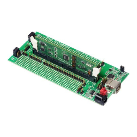
2 eZ430-TMS37157 Development Tool.................................................................................... 8
3 Kit Contents ................................................................................................................ 10
4 RFID Base Station With Mounted Antenna ............................................................................ 11
5 DC Power Plug ............................................................................................................ 12
6 Windows XP Hardware Recognition.................................................................................... 12
7 Windows XP Hardware Recognition for MSP430 Application UART............................................... 12
8 Found New Hardware Wizard, Step 1.................................................................................. 13
9 Found New Hardware Wizard, Step 2.................................................................................. 13
10 Hardware Installation...................................................................................................... 14
11 RFID Base Station in Device Manager................................................................................. 14
12 Connection of TMS37157 to the Battery Board ....................................................................... 15
13 eZ430-TMS37157 in Front of RFID Base Station..................................................................... 15
14 RFID Demo Software: Startup Screen ................................................................................. 16
15 RFID Demo Software: Com Port Tab................................................................................... 17
16 RFID Demo Software: Demo Mode..................................................................................... 18
17 TMS37157 Target Board ................................................................................................. 19
18 RFID Demo Software: Direct Access Mode............................................................................ 20
19 RFID Demo Software: Direct Access Mode, Program Page......................................................... 20
20 RFID Demo Software: Fail Message.................................................................................... 22
21 Demo 1 - SPI Access to MSP430 Mode ............................................................................... 23
22 Demo 2 - Configuration Memory Mode................................................................................. 24
23 Demo 3 - Check Battery Level Mode: High............................................................................ 25
24 Demo 3 - Check Battery Level Mode: Medium........................................................................ 26
25 Demo 3 - Check Battery Level Mode: Low............................................................................. 26
26 Demo 4 - Read Page ..................................................................................................... 27
27 Demo 5 - TMS37157 Memory Map ..................................................................................... 28
28 Demo 5 - Read Serial Number .......................................................................................... 28
29 Demo 6 - Read Page 2................................................................................................... 29
30 Demo 6 - Program Page 2 ............................................................................................... 30
31 Flow Diagram of Main Routine .......................................................................................... 31
32 Flow Diagram of Push Button Routine.................................................................................. 32
33 Flow Diagram of MSP Access Routine................................................................................. 33
34 Flow Diagram of Auto Trim Routine..................................................................................... 34
35 eZ430-RF2500 USB Debugging Interface 6-Pin Male Header...................................................... 36
36 9600 bps With No Flow Control ......................................................................................... 36
37 eZ430-RF USB Debugging Interface Schematic 1.................................................................... 38
38 eZ430-RF USB Debugging Interface Schematic 2.................................................................... 39
39 eZ430-TMS37157 Target Board Schematic ........................................................................... 40
40 eZ430-RF USB Debugging Interface, PCB Components Layout ................................................... 41
41 eZ430-RF USB Debugging Interface, PCB Layout ................................................................... 41
42 eZ430-TMS37157 Target Board, PCB Layout......................................................................... 41
43 RFID Base Station Schematic........................................................................................... 42
44 RFID Base Station Connector Schematic.............................................................................. 43
45 RFID Base Station Interface Board Schematic........................................................................ 44
4List of Figures SLAU281B–November 2009–Revised March 2010
Submit Documentation Feedback
Copyright ©2009–2010, Texas Instruments Incorporated
