manuals.online logo
Brands
  1. Home
  2. •
  3. Brands
  4. •
  5. Texas Instruments
  6. •
  7. Computer Hardware
  8. •
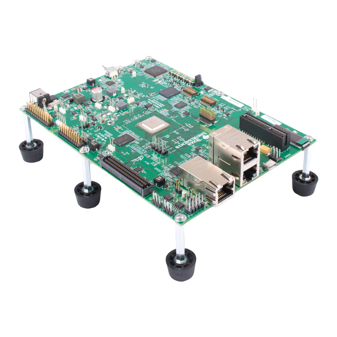
  9. Texas Instruments AM335 Series Product manual

Texas Instruments AM335 Series Product manual

AM335x ARM®Cortex™-A8 Microprocessors
(MPUs)
Technical Reference Manual
Literature Number: SPRUH73H
October 2011–Revised April 2013
Contents
Preface .................................................................................................................................... 149
1 Introduction .................................................................................................................... 150
1.1 AM335x Family ........................................................................................................... 150
1.1.1 Device Features ................................................................................................. 150
1.1.2 Device Identification ............................................................................................ 151
1.1.3 Feature Identification ........................................................................................... 151
1.2 Silicon Revision Functional Differences and Enhancements ....................................................... 153
1.2.1 Added RTC Alarm Wakeup for DeepSleep Modes ......................................................... 153
1.2.2 Changed BOOTP Identifier .................................................................................... 153
1.2.3 Changed Product String in USB Descriptor ................................................................. 153
1.2.4 Added DPLL Power Switch Control and Status Registers ................................................ 153
1.2.5 Added Control for CORE SRAM LDO Retention Mode .................................................... 153
1.2.6 Added Pin Mux Options for GPMC_A9 to Facilitate RMII Pin Muxing ................................... 153
1.2.7 Changed Polarity of Input Signal nNMI (Pin EXTINTn) .................................................... 153
1.2.8 Changed Default Value of ncin and pcin Bits in vtp_ctrl Register ........................................ 154
1.2.9 Changed Default Value of RGMII Mode to No Internal Delay ............................................ 154
1.2.10 Changed Default Value of RMII Clock Source ............................................................. 154
1.2.11 Changed the Method of Determining Speed of Operation During EMAC Boot ........................ 154
1.2.12 Added EFUSE_SMA Register for Help Identifying Different Device Variants ......................... 154
2 Memory Map ................................................................................................................... 155
2.1 ARM Cortex-A8 Memory Map .......................................................................................... 155
3 ARM MPU Subsystem ....................................................................................................... 164
3.1 ARM Cortex-A8 MPU Subsystem ...................................................................................... 165
3.1.1 Features .......................................................................................................... 166
3.1.2 MPU Subsystem Integration ................................................................................... 166
3.1.3 MPU Subsystem Clock and Reset Distribution ............................................................. 167
3.1.4 ARM Subchip .................................................................................................... 170
3.1.5 Interrupt Controller .............................................................................................. 171
3.1.6 Power Management ............................................................................................ 171
3.1.7 ARM Programming Model ..................................................................................... 174
4 Programmable Real-Time Unit and Industrial Communication Subsystem (PRU-ICSS) ............. 176
4.1 Introduction ............................................................................................................... 177
5 Graphics Accelerator (SGX) .............................................................................................. 178
5.1 Introduction ............................................................................................................... 179
5.1.1 POWERVR SGX Main Features .............................................................................. 179
5.1.2 SGX 3D Features ............................................................................................... 179
5.1.3 Universal Scalable Shader Engine (USSE) – Key Features .............................................. 180
5.1.4 Unsupported Features .......................................................................................... 181
5.2 Integration ................................................................................................................. 182
5.2.1 SGX530 Connectivity Attributes ............................................................................... 182
5.2.2 SGX530 Clock and Reset Management ..................................................................... 182
5.2.3 SGX530 Pin List ................................................................................................. 183
5.3 Functional Description ................................................................................................... 184
5.3.1 SGX Block Diagram ............................................................................................ 184
2Contents SPRUH73H–October 2011–Revised April 2013
Submit Documentation Feedback
Copyright © 2011–2013, Texas Instruments Incorporated
www.ti.com
5.3.2 SGX Elements Description .................................................................................... 184
6 Interrupts ........................................................................................................................ 186
6.1 Functional Description ................................................................................................... 187
6.1.1 Interrupt Processing ............................................................................................ 188
6.1.2 Register Protection ............................................................................................. 189
6.1.3 Module Power Saving .......................................................................................... 189
6.1.4 Error Handling ................................................................................................... 189
6.1.5 Interrupt Handling ............................................................................................... 189
6.2 Basic Programming Model .............................................................................................. 190
6.2.1 Initialization Sequence ......................................................................................... 190
6.2.2 INTC Processing Sequence ................................................................................... 190
6.2.3 INTC Preemptive Processing Sequence ..................................................................... 194
6.2.4 Interrupt Preemption ............................................................................................ 198
6.2.5 ARM A8 INTC Spurious Interrupt Handling ................................................................. 198
6.3 ARM Cortex-A8 Interrupts .............................................................................................. 199
6.4 PWM Events .............................................................................................................. 203
6.5 Interrupt Controller Registers ........................................................................................... 204
6.5.1 INTC Registers .................................................................................................. 204
7 Memory Subsystem ......................................................................................................... 250
7.1 GPMC ..................................................................................................................... 251
7.1.1 Introduction ...................................................................................................... 251
7.1.2 Integration ........................................................................................................ 254
7.1.3 Functional Description .......................................................................................... 256
7.1.4 Use Cases ....................................................................................................... 355
7.1.5 Registers ......................................................................................................... 366
7.2 OCMC-RAM .............................................................................................................. 398
7.2.1 Introduction ...................................................................................................... 398
7.2.2 Integration ........................................................................................................ 399
7.3 EMIF ....................................................................................................................... 400
7.3.1 Introduction ...................................................................................................... 400
7.3.2 Integration ........................................................................................................ 402
7.3.3 Functional Description .......................................................................................... 404
7.3.4 Use Cases ....................................................................................................... 422
7.3.5 EMIF4D Registers .............................................................................................. 422
7.3.6 DDR2/3/mDDR PHY Registers ............................................................................... 467
7.4 ELM ........................................................................................................................ 476
7.4.1 Introduction ...................................................................................................... 476
7.4.2 Integration ........................................................................................................ 477
7.4.3 Functional Description .......................................................................................... 478
7.4.4 Basic Programming Model ..................................................................................... 481
7.4.5 ELM Registers ................................................................................................... 487
8 Power, Reset, and Clock Management (PRCM) .................................................................... 499
8.1 Power, Reset, and Clock Management ............................................................................... 500
8.1.1 Introduction ...................................................................................................... 500
8.1.2 Device Power-Management Architecture Building Blocks ................................................. 500
8.1.3 Clock Management ............................................................................................. 500
8.1.4 Power Management ............................................................................................ 506
8.1.5 PRCM Module Overview ....................................................................................... 517
8.1.6 Clock Generation and Management .......................................................................... 519
8.1.7 Reset Management ............................................................................................. 535
8.1.8 Power-Up/Down Sequence .................................................................................... 544
8.1.9 IO State ........................................................................................................... 544
8.1.10 Voltage and Power Domains ................................................................................. 544
3
SPRUH73H–October 2011–Revised April 2013 Contents
Submit Documentation Feedback Copyright © 2011–2013, Texas Instruments Incorporated
www.ti.com
8.1.11 Device Modules and Power Management Attributes List ................................................. 545
8.1.12 Clock Module Registers ....................................................................................... 548
8.1.13 Power Management Registers ............................................................................... 705
9 Control Module ................................................................................................................ 746
9.1 Introduction ............................................................................................................... 747
9.2 Functional Description ................................................................................................... 747
9.2.1 Control Module Initialization ................................................................................... 747
9.2.2 Pad Control Registers .......................................................................................... 747
9.2.3 EDMA Event Multiplexing ...................................................................................... 748
9.2.4 Device Control and Status ..................................................................................... 749
9.2.5 DDR PHY ........................................................................................................ 756
9.3 CONTROL_MODULE Registers ....................................................................................... 757
9.3.1 control_revision Register (offset = 0h) [reset = 0h] ......................................................... 762
9.3.2 control_hwinfo Register (offset = 4h) [reset = 0h] .......................................................... 763
9.3.3 control_sysconfig Register (offset = 10h) [reset = 0h] ..................................................... 764
9.3.4 control_status Register (offset = 40h) [reset = 0h] ......................................................... 765
9.3.5 control_emif_sdram_config Register (offset = 110h) [reset = 0h] ........................................ 766
9.3.6 core_sldo_ctrl Register (offset = 428h) [reset = 0h] ........................................................ 768
9.3.7 mpu_sldo_ctrl Register (offset = 42Ch) [reset = 0h] ....................................................... 769
9.3.8 clk32kdivratio_ctrl Register (offset = 444h) [reset = 0h] ................................................... 770
9.3.9 bandgap_ctrl Register (offset = 448h) [reset = 0h] ......................................................... 771
9.3.10 bandgap_trim Register (offset = 44Ch) [reset = 0h] ....................................................... 772
9.3.11 pll_clkinpulow_ctrl Register (offset = 458h) [reset = 0h] .................................................. 773
9.3.12 mosc_ctrl Register (offset = 468h) [reset = 0h] ............................................................ 774
9.3.13 deepsleep_ctrl Register (offset = 470h) [reset = 0h] ...................................................... 775
9.3.14 dpll_pwr_sw_status (offset = 50Ch) [reset = 0h] .......................................................... 776
9.3.15 device_id Register (offset = 600h) [reset = 0x] ............................................................ 777
9.3.16 dev_feature Register (offset = 604h) [reset = 0h] ......................................................... 778
9.3.17 init_priority_0 Register (offset = 608h) [reset = 0h] ........................................................ 779
9.3.18 init_priority_1 Register (offset = 60Ch) [reset = 0h] ....................................................... 780
9.3.19 mmu_cfg Register (offset = 610h) [reset = 0h] ............................................................. 781
9.3.20 tptc_cfg Register (offset = 614h) [reset = 0h] .............................................................. 782
9.3.21 usb_ctrl0 Register (offset = 620h) [reset = 0h] ............................................................. 783
9.3.22 usb_sts0 Register (offset = 624h) [reset = 0h] ............................................................. 785
9.3.23 usb_ctrl1 Register (offset = 628h) [reset = 0h] ............................................................. 786
9.3.24 usb_sts1 Register (offset = 62Ch) [reset = 0h] ............................................................ 788
9.3.25 mac_id0_lo Register (offset = 630h) [reset = 0h] .......................................................... 789
9.3.26 mac_id0_hi Register (offset = 634h) [reset = 0h] .......................................................... 790
9.3.27 mac_id1_lo Register (offset = 638h) [reset = 0h] .......................................................... 791
9.3.28 mac_id1_hi Register (offset = 63Ch) [reset = 0h] ......................................................... 792
9.3.29 dcan_raminit Register (offset = 644h) [reset = 0h] ........................................................ 793
9.3.30 usb_wkup_ctrl Register (offset = 648h) [reset = 0h] ...................................................... 794
9.3.31 gmii_sel Register (offset = 650h) [reset = 0h] .............................................................. 795
9.3.32 pwmss_ctrl Register (offset = 664h) [reset = 0h] .......................................................... 796
9.3.33 mreqprio_0 Register (offset = 670h) [reset = 0h] .......................................................... 797
9.3.34 mreqprio_1 Register (offset = 674h) [reset = 0h] .......................................................... 798
9.3.35 hw_event_sel_grp1 Register (offset = 690h) [reset = 0h] ................................................ 799
9.3.36 hw_event_sel_grp2 Register (offset = 694h) [reset = 0h] ................................................ 800
9.3.37 hw_event_sel_grp3 Register (offset = 698h) [reset = 0h] ................................................ 801
9.3.38 hw_event_sel_grp4 Register (offset = 69Ch) [reset = 0h] ................................................ 802
9.3.39 smrt_ctrl Register (offset = 6A0h) [reset = 0h] ............................................................. 803
9.3.40 mpuss_hw_debug_sel Register (offset = 6A4h) [reset = 0h] ............................................ 804
9.3.41 mpuss_hw_dbg_info Register (offset = 6A8h) [reset = 0h] ............................................... 805
4Contents SPRUH73H–October 2011–Revised April 2013
Submit Documentation Feedback
Copyright © 2011–2013, Texas Instruments Incorporated
www.ti.com
9.3.42 vdd_mpu_opp_050 Register (offset = 770h) [reset = 0h] ................................................. 806
9.3.43 vdd_mpu_opp_100 Register (offset = 774h) [reset = 0h] ................................................. 807
9.3.44 vdd_mpu_opp_120 Register (offset = 778h) [reset = 0h] ................................................. 808
9.3.45 vdd_mpu_opp_turbo Register (offset = 77Ch) [reset = 0h] .............................................. 809
9.3.46 vdd_core_opp_050 Register (offset = 7B8h) [reset = 0h] ................................................ 810
9.3.47 vdd_core_opp_100 Register (offset = 7BCh) [reset = 0h] ................................................ 811
9.3.48 bb_scale Register (offset = 7D0h) [reset = 0h] ............................................................ 812
9.3.49 usb_vid_pid Register (offset = 7F4h) [reset = 4516141h] ................................................ 813
9.3.50 efuse_sma Register (offset = 7FCh) [reset = 0h] .......................................................... 814
9.3.51 conf_<module>_<pin> Register (offset = 800h–A34h) ................................................... 815
9.3.52 cqdetect_status Register (offset = E00h) [reset = 0h] .................................................... 816
9.3.53 ddr_io_ctrl Register (offset = E04h) [reset = 0h] ........................................................... 817
9.3.54 vtp_ctrl Register (offset = E0Ch) [reset = 0h] .............................................................. 818
9.3.55 vref_ctrl Register (offset = E14h) [reset = 0h] .............................................................. 819
9.3.56 tpcc_evt_mux_0_3 Register (offset = F90h) [reset = 0h] ................................................. 820
9.3.57 tpcc_evt_mux_4_7 Register (offset = F94h) [reset = 0h] ................................................. 821
9.3.58 tpcc_evt_mux_8_11 Register (offset = F98h) [reset = 0h] ............................................... 822
9.3.59 tpcc_evt_mux_12_15 Register (offset = F9Ch) [reset = 0h] ............................................. 823
9.3.60 tpcc_evt_mux_16_19 Register (offset = FA0h) [reset = 0h] .............................................. 824
9.3.61 tpcc_evt_mux_20_23 Register (offset = FA4h) [reset = 0h] .............................................. 825
9.3.62 tpcc_evt_mux_24_27 Register (offset = FA8h) [reset = 0h] .............................................. 826
9.3.63 tpcc_evt_mux_28_31 Register (offset = FACh) [reset = 0h] ............................................. 827
9.3.64 tpcc_evt_mux_32_35 Register (offset = FB0h) [reset = 0h] .............................................. 828
9.3.65 tpcc_evt_mux_36_39 Register (offset = FB4h) [reset = 0h] .............................................. 829
9.3.66 tpcc_evt_mux_40_43 Register (offset = FB8h) [reset = 0h] .............................................. 830
9.3.67 tpcc_evt_mux_44_47 Register (offset = FBCh) [reset = 0h] ............................................. 831
9.3.68 tpcc_evt_mux_48_51 Register (offset = FC0h) [reset = 0h] ............................................. 832
9.3.69 tpcc_evt_mux_52_55 Register (offset = FC4h) [reset = 0h] ............................................. 833
9.3.70 tpcc_evt_mux_56_59 Register (offset = FC8h) [reset = 0h] ............................................. 834
9.3.71 tpcc_evt_mux_60_63 Register (offset = FCCh) [reset = 0h] ............................................. 835
9.3.72 timer_evt_capt Register (offset = FD0h) [reset = 0h] ..................................................... 836
9.3.73 ecap_evt_capt Register (offset = FD4h) [reset = 0h] ..................................................... 837
9.3.74 adc_evt_capt Register (offset = FD8h) [reset = 0h] ....................................................... 838
9.3.75 reset_iso Register (offset = 1000h) [reset = 0h] ........................................................... 839
9.3.76 dpll_pwr_sw_ctrl Register (offset = 1318h) [reset = 0h] .................................................. 840
9.3.77 ddr_cke_ctrl Register (offset = 131Ch) [reset = 0h] ....................................................... 842
9.3.78 sma2 Register (offset = 1320h) [reset = 0h] ................................................................ 843
9.3.79 m3_txev_eoi Register (offset = 1324h) [reset = 0h] ....................................................... 844
9.3.80 ipc_msg_reg0 Register (offset = 1328h) [reset = 0h] ..................................................... 845
9.3.81 ipc_msg_reg1 Register (offset = 132Ch) [reset = 0h] ..................................................... 846
9.3.82 ipc_msg_reg2 Register (offset = 1330h) [reset = 0h] ..................................................... 847
9.3.83 ipc_msg_reg3 Register (offset = 1334h) [reset = 0h] ..................................................... 848
9.3.84 ipc_msg_reg4 Register (offset = 1338h) [reset = 0h] ..................................................... 849
9.3.85 ipc_msg_reg5 Register (offset = 133Ch) [reset = 0h] ..................................................... 850
9.3.86 ipc_msg_reg6 Register (offset = 1340h) [reset = 0h] ..................................................... 851
9.3.87 ipc_msg_reg7 Register (offset = 1344h) [reset = 0h] ..................................................... 852
9.3.88 ddr_cmd0_ioctrl Register (offset = 1404h) [reset = 0h] ................................................... 853
9.3.89 ddr_cmd1_ioctrl Register (offset = 1408h) [reset = 0h] ................................................... 855
9.3.90 ddr_cmd2_ioctrl Register (offset = 140Ch) [reset = 0h] .................................................. 857
9.3.91 ddr_data0_ioctrl Register (offset = 1440h) [reset = 0h] ................................................... 859
9.3.92 ddr_data1_ioctrl Register (offset = 1444h) [reset = 0h] ................................................... 861
10 Interconnects .................................................................................................................. 863
10.1 Introduction ............................................................................................................... 864
5
SPRUH73H–October 2011–Revised April 2013 Contents
Submit Documentation Feedback Copyright © 2011–2013, Texas Instruments Incorporated
www.ti.com
10.1.1 Terminology ..................................................................................................... 864
10.1.2 L3 Interconnect ................................................................................................. 864
10.1.3 L4 Interconnect ................................................................................................. 868
11 Enhanced Direct Memory Access (EDMA) ........................................................................... 869
11.1 Introduction ............................................................................................................... 870
11.1.1 EDMA3 Controller Block Diagram ........................................................................... 870
11.1.2 Third-Party Channel Controller (TPCC) Overview ......................................................... 870
11.1.3 Third-Party Transfer Controller (TPTC) Overview ......................................................... 871
11.2 Integration ................................................................................................................. 873
11.2.1 Third-Party Channel Controller (TPCC) Integration ....................................................... 873
11.2.2 Third-Party Transfer Controller (TPTC) Integration ....................................................... 874
11.3 Functional Description ................................................................................................... 876
11.3.1 Functional Overview ........................................................................................... 876
11.3.2 Types of EDMA3 Transfers ................................................................................... 879
11.3.3 Parameter RAM (PaRAM) .................................................................................... 881
11.3.4 Initiating a DMA Transfer ..................................................................................... 893
11.3.5 Completion of a DMA Transfer ............................................................................... 896
11.3.6 Event, Channel, and PaRAM Mapping ...................................................................... 897
11.3.7 EDMA3 Channel Controller Regions ........................................................................ 899
11.3.8 Chaining EDMA3 Channels .................................................................................. 901
11.3.9 EDMA3 Interrupts .............................................................................................. 902
11.3.10 Memory Protection ........................................................................................... 908
11.3.11 Event Queue(s) ............................................................................................... 912
11.3.12 EDMA3 Transfer Controller (EDMA3TC) .................................................................. 914
11.3.13 Event Dataflow ................................................................................................ 917
11.3.14 EDMA3 Prioritization ......................................................................................... 917
11.3.15 EDMA3 Operating Frequency (Clock Control) ............................................................ 918
11.3.16 Reset Considerations ........................................................................................ 918
11.3.17 Power Management .......................................................................................... 918
11.3.18 Emulation Considerations ................................................................................... 918
11.3.19 EDMA Transfer Examples ................................................................................... 920
11.3.20 EDMA Events ................................................................................................. 936
11.4 EDMA3 Registers ........................................................................................................ 939
11.4.1 EDMA3 Channel Controller Registers ....................................................................... 939
11.4.2 EDMA3 Transfer Controller Registers ....................................................................... 993
11.5 Appendix A .............................................................................................................. 1018
11.5.1 Debug Checklist .............................................................................................. 1018
11.5.2 Miscellaneous Programming/Debug Tips ................................................................. 1019
11.5.3 Setting Up a Transfer ........................................................................................ 1020
12 Touchscreen Controller .................................................................................................. 1022
12.1 Introduction .............................................................................................................. 1023
12.1.1 TSC_ADC Features .......................................................................................... 1023
12.1.2 Unsupported TSC_ADC_SS Features .................................................................... 1023
12.2 Integration ............................................................................................................... 1024
12.2.1 TSC_ADC Connectivity Attributes .......................................................................... 1024
12.2.2 TSC_ADC Clock and Reset Management ................................................................ 1025
12.2.3 TSC_ADC Pin List ............................................................................................ 1025
12.3 Functional Description ................................................................................................. 1026
12.3.1 HW Synchronized or SW Channels ........................................................................ 1026
12.3.2 Open Delay and Sample Delay ............................................................................. 1026
12.3.3 Averaging of Samples (1, 2, 4, 8, and 16) ................................................................ 1026
12.3.4 One-Shot (Single) or Continuous Mode ................................................................... 1026
12.3.5 Interrupts ...................................................................................................... 1026
6Contents SPRUH73H–October 2011–Revised April 2013
Submit Documentation Feedback
Copyright © 2011–2013, Texas Instruments Incorporated
www.ti.com
12.3.6 DMA Requests ................................................................................................ 1027
12.3.7 Analog Front End (AFE) Functional Block Diagram ..................................................... 1027
12.4 Operational Modes ..................................................................................................... 1029
12.4.1 PenCtrl and PenIRQ ......................................................................................... 1030
12.5 Touchscreen Controller Registers .................................................................................... 1033
12.5.1 TSC_ADC_SS Registers .................................................................................... 1033
13 LCD Controller ............................................................................................................... 1097
13.1 Introduction .............................................................................................................. 1098
13.1.1 Purpose of the Peripheral ................................................................................... 1098
13.1.2 Features ....................................................................................................... 1099
13.2 Integration ............................................................................................................... 1100
13.2.1 LCD Controller Connectivity Attributes .................................................................... 1100
13.2.2 LCD Controller Clock and Reset Management ........................................................... 1101
13.2.3 LCD Controller Pin List ...................................................................................... 1101
13.3 Functional Description ................................................................................................. 1102
13.3.1 Clocking ........................................................................................................ 1102
13.3.2 LCD External I/O Signals .................................................................................... 1104
13.3.3 DMA Engine ................................................................................................... 1105
13.3.4 LIDD Controller ............................................................................................... 1106
13.3.5 Raster Controller ............................................................................................. 1108
13.3.6 Interrupt Conditions .......................................................................................... 1119
13.3.7 DMA ............................................................................................................ 1121
13.3.8 Power Management .......................................................................................... 1121
13.4 Programming Model .................................................................................................... 1122
13.4.1 LCD Character Displays ..................................................................................... 1122
13.4.2 Active Matrix Displays ....................................................................................... 1125
13.4.3 System Interaction ........................................................................................... 1125
13.4.4 Palette Lookup ................................................................................................ 1125
13.4.5 Test Logic ..................................................................................................... 1127
13.4.6 Disable and Software Reset Sequence ................................................................... 1127
13.4.7 Precedence Order for Determining Frame Buffer Type ................................................. 1128
13.5 LCD Registers .......................................................................................................... 1128
13.5.1 PID Register (offset = 0h) [reset = 0h] ..................................................................... 1130
13.5.2 CTRL Register (offset = 4h) [reset = 0h] .................................................................. 1131
13.5.3 LIDD_CTRL Register (offset = Ch) [reset = 0h] .......................................................... 1132
13.5.4 LIDD_CS0_CONF Register (offset = 10h) [reset = 0h] .................................................. 1133
13.5.5 LIDD_CS0_ADDR Register (offset = 14h) [reset = 0h] .................................................. 1134
13.5.6 LIDD_CS0_DATA Register (offset = 18h) [reset = 0h] .................................................. 1135
13.5.7 LIDD_CS1_CONF Register (offset = 1Ch) [reset = 0h] ................................................. 1136
13.5.8 LIDD_CS1_ADDR Register (offset = 20h) [reset = 0h] .................................................. 1137
13.5.9 LIDD_CS1_DATA Register (offset = 24h) [reset = 0h] .................................................. 1138
13.5.10 RASTER_CTRL Register (offset = 28h) [reset = 0h] ................................................... 1139
13.5.11 RASTER_TIMING_0 Register (offset = 2Ch) [reset = 0h] ............................................. 1141
13.5.12 RASTER_TIMING_1 Register (offset = 30h) [reset = 0h] ............................................. 1142
13.5.13 RASTER_TIMING_2 Register (offset = 34h) [reset = 0h] ............................................. 1143
13.5.14 RASTER_SUBPANEL Register (offset = 38h) [reset = 0h] ........................................... 1145
13.5.15 RASTER_SUBPANEL2 Register (offset = 3Ch) [reset = 0h] ......................................... 1146
13.5.16 LCDDMA_CTRL Register (offset = 40h) [reset = 0h] .................................................. 1147
13.5.17 LCDDMA_FB0_BASE Register (offset = 44h) [reset = 0h] ............................................ 1148
13.5.18 LCDDMA_FB0_CEILING Register (offset = 48h) [reset = 0h] ........................................ 1149
13.5.19 LCDDMA_FB1_BASE Register (offset = 4Ch) [reset = 0h] ........................................... 1150
13.5.20 LCDDMA_FB1_CEILING Register (offset = 50h) [reset = 0h] ........................................ 1151
13.5.21 SYSCONFIG Register (offset = 54h) [reset = 0h] ...................................................... 1152
7
SPRUH73H–October 2011–Revised April 2013 Contents
Submit Documentation Feedback Copyright © 2011–2013, Texas Instruments Incorporated
www.ti.com
13.5.22 IRQSTATUS_RAW Register (offset = 58h) [reset = 0h] ............................................... 1153
13.5.23 IRQSTATUS Register (offset = 5Ch) [reset = 0h] ...................................................... 1155
13.5.24 IRQENABLE_SET Register (offset = 60h) [reset = 0h] ................................................ 1157
13.5.25 IRQENABLE_CLEAR Register (offset = 64h) [reset = 0h] ............................................ 1159
13.5.26 CLKC_ENABLE Register (offset = 6Ch) [reset = 0h] .................................................. 1161
13.5.27 CLKC_RESET Register (offset = 70h) [reset = 0h] .................................................... 1162
14 Ethernet Subsystem ....................................................................................................... 1163
14.1 Introduction .............................................................................................................. 1164
14.1.1 Features ....................................................................................................... 1164
14.1.2 Unsupported Features ....................................................................................... 1165
14.2 Integration ............................................................................................................... 1166
14.2.1 Ethernet Switch Connectivity Attributes ................................................................... 1167
14.2.2 Ethernet Switch Clock and Reset Management .......................................................... 1168
14.2.3 Ethernet Switch Pin List ..................................................................................... 1169
14.2.4 Ethernet Switch RMII Clocking Details .................................................................... 1169
14.2.5 GMII Interface Signal Connections and Descriptions .................................................... 1170
14.2.6 RMII Signal Connections and Descriptions ............................................................... 1173
14.2.7 RGMII Signal Connections and Descriptions ............................................................. 1174
14.3 Functional Description ................................................................................................. 1176
14.3.1 CPSW_3G Subsystem ....................................................................................... 1176
14.3.2 CPSW_3G ..................................................................................................... 1181
14.3.3 Ethernet Mac Sliver (CPGMAC_SL) ....................................................................... 1223
14.3.4 Command IDLE ............................................................................................... 1225
14.3.5 RMII Interface ................................................................................................. 1225
14.3.6 RGMII Interface ............................................................................................... 1226
14.3.7 Common Platform Time Sync (CPTS) ..................................................................... 1228
14.3.8 MDIO ........................................................................................................... 1233
14.4 Software Operation ..................................................................................................... 1235
14.4.1 Transmit Operation ........................................................................................... 1235
14.4.2 Receive Operation ........................................................................................... 1237
14.4.3 Initializing the MDIO Module ................................................................................ 1238
14.4.4 Writing Data to a PHY Register ............................................................................ 1238
14.4.5 Reading Data from a PHY Register ........................................................................ 1239
14.4.6 Initialization and Configuration of CPSW .................................................................. 1239
14.5 Ethernet Subsystem Registers ....................................................................................... 1240
14.5.1 CPSW_ALE Registers ....................................................................................... 1240
14.5.2 CPSW_CPDMA Registers .................................................................................. 1255
14.5.3 CPSW_CPTS Registers ..................................................................................... 1308
14.5.4 CPSW_STATS Registers ................................................................................... 1321
14.5.5 CPDMA_STATERAM Registers ............................................................................ 1321
14.5.6 CPSW_PORT Registers ..................................................................................... 1355
14.5.7 CPSW_SL Registers ......................................................................................... 1410
14.5.8 CPSW_SS Registers ........................................................................................ 1424
14.5.9 CPSW_WR Registers ........................................................................................ 1437
14.5.10 Management Data Input/Output (MDIO) Registers ..................................................... 1473
15 Pulse-Width Modulation Subsystem (PWMSS) ................................................................... 1485
15.1 Pulse-Width Modulation Subsystem (PWMSS) .................................................................... 1486
15.1.1 Introduction .................................................................................................... 1486
15.1.2 Integration ..................................................................................................... 1488
15.1.3 PWMSS Registers ........................................................................................... 1489
15.2 Enhanced PWM (ePWM) Module .................................................................................... 1494
15.2.1 Introduction .................................................................................................... 1494
15.2.2 Functional Description ....................................................................................... 1498
8Contents SPRUH73H–October 2011–Revised April 2013
Submit Documentation Feedback
Copyright © 2011–2013, Texas Instruments Incorporated
www.ti.com
15.2.3 Use Cases ..................................................................................................... 1557
15.2.4 Registers ...................................................................................................... 1581
15.3 Enhanced Capture (eCAP) Module .................................................................................. 1607
15.3.1 Introduction .................................................................................................... 1607
15.3.2 Functional Description ....................................................................................... 1608
15.3.3 Use Cases ..................................................................................................... 1618
15.3.4 Registers ...................................................................................................... 1634
15.4 Enhanced Quadrature Encoder Pulse (eQEP) Module ........................................................... 1650
15.4.1 Introduction .................................................................................................... 1650
15.4.2 Functional Description ....................................................................................... 1653
15.4.3 eQEP Registers .............................................................................................. 1672
16 Universal Serial Bus (USB) .............................................................................................. 1690
16.1 Introduction .............................................................................................................. 1691
16.1.1 Acronyms, Abbreviations, and Definitions ................................................................. 1691
16.1.2 USB Features ................................................................................................. 1692
16.1.3 Unsupported USB OTG and PHY Features .............................................................. 1693
16.2 Integration ............................................................................................................... 1694
16.2.1 USB Connectivity Attributes ................................................................................. 1694
16.2.2 USB Clock and Reset Management ....................................................................... 1695
16.2.3 USB Pin List ................................................................................................... 1695
16.2.4 USB GPIO Details ............................................................................................ 1695
16.2.5 USB Unbonded PHY Pads .................................................................................. 1696
16.3 Functional Description ................................................................................................. 1697
16.3.1 VBUS Voltage Sourcing Control ............................................................................ 1697
16.3.2 Pullup/PullDown Resistors .................................................................................. 1697
16.3.3 Role Assuming Method ...................................................................................... 1698
16.3.4 Clock, PLL, and PHY Initialization ......................................................................... 1698
16.3.5 Indexed and Non-Indexed Register Spaces .............................................................. 1698
16.3.6 Dynamic FIFO Sizing ........................................................................................ 1698
16.3.7 USB Controller Host and Peripheral Modes Operation .................................................. 1699
16.3.8 Protocol Description(s) ....................................................................................... 1701
16.3.9 Communications Port Programming Interface (CPPI) 4.1 DMA ....................................... 1734
16.3.10 USB 2.0 Test Modes ....................................................................................... 1758
16.4 Supported Use Cases ................................................................................................. 1759
16.5 USB Registers .......................................................................................................... 1760
16.5.1 USBSS Registers ............................................................................................. 1760
16.5.2 USB0_CTRL Registers ...................................................................................... 1803
16.5.3 USB1_CTRL Registers ...................................................................................... 1853
16.5.4 USB2PHY Registers ......................................................................................... 1901
16.5.5 CPPI_DMA Registers ........................................................................................ 1925
16.5.6 CPPI_DMA_SCHEDULER Registers ...................................................................... 2081
16.5.7 QUEUE_MGR Registers .................................................................................... 2084
17 Interprocessor Communication ........................................................................................ 3235
17.1 Mailbox ................................................................................................................... 3236
17.1.1 Introduction .................................................................................................... 3236
17.1.2 Integration ..................................................................................................... 3237
17.1.3 Functional Description ....................................................................................... 3238
17.1.4 Programming Guide .......................................................................................... 3242
17.1.5 MAILBOX Registers .......................................................................................... 3245
17.2 Spinlock .................................................................................................................. 3306
17.2.1 SPINLOCK Registers ........................................................................................ 3306
18 Multimedia Card (MMC) ................................................................................................... 3344
18.1 Introduction .............................................................................................................. 3345
9
SPRUH73H–October 2011–Revised April 2013 Contents
Submit Documentation Feedback Copyright © 2011–2013, Texas Instruments Incorporated
www.ti.com
18.1.1 MMCHS Features ............................................................................................ 3345
18.1.2 Unsupported MMCHS Features ............................................................................ 3345
18.2 Integration ............................................................................................................... 3346
18.2.1 MMCHS Connectivity Attributes ............................................................................ 3347
18.2.2 MMCHS Clock and Reset Management .................................................................. 3348
18.2.3 MMCHS Pin List .............................................................................................. 3348
18.3 Functional Description ................................................................................................. 3350
18.3.1 MMC/SD/SDIO Functional Modes ......................................................................... 3350
18.3.2 Resets ......................................................................................................... 3357
18.3.3 Power Management .......................................................................................... 3358
18.3.4 Interrupt Requests ............................................................................................ 3361
18.3.5 DMA Modes ................................................................................................... 3363
18.3.6 Mode Selection ............................................................................................... 3366
18.3.7 Buffer Management .......................................................................................... 3366
18.3.8 Transfer Process ............................................................................................. 3369
18.3.9 Transfer or Command Status and Error Reporting ...................................................... 3370
18.3.10 Auto Command 12 Timings ................................................................................ 3375
18.3.11 Transfer Stop ................................................................................................ 3377
18.3.12 Output Signals Generation ................................................................................ 3378
18.3.13 Card Boot Mode Management ............................................................................ 3380
18.3.14 CE-ATA Command Completion Disable Management ................................................ 3382
18.3.15 Test Registers ............................................................................................... 3382
18.3.16 MMC/SD/SDIO Hardware Status Features .............................................................. 3383
18.4 Low-Level Programming Models ..................................................................................... 3384
18.4.1 Surrounding Modules Global Initialization ................................................................. 3384
18.4.2 MMC/SD/SDIO Controller Initialization Flow .............................................................. 3384
18.4.3 Operational Modes Configuration .......................................................................... 3387
18.5 Multimedia Card Registers ............................................................................................ 3389
18.5.1 MULTIMEDIA_CARD Registers ............................................................................ 3389
19 Universal Asynchronous Receiver/Transmitter (UART) ....................................................... 3446
19.1 Introduction .............................................................................................................. 3447
19.1.1 UART Mode Features ........................................................................................ 3447
19.1.2 IrDA Mode Features ......................................................................................... 3447
19.1.3 CIR Mode Features .......................................................................................... 3447
19.1.4 Unsupported UART Features ............................................................................... 3447
19.2 Integration ............................................................................................................... 3449
19.2.1 UART Connectivity Attributes ............................................................................... 3449
19.2.2 UART Clock and Reset Management ..................................................................... 3450
19.2.3 UART Pin List ................................................................................................. 3452
19.3 Functional Description ................................................................................................. 3453
19.3.1 Block Diagram ................................................................................................ 3453
19.3.2 Clock Configuration .......................................................................................... 3454
19.3.3 Software Reset ............................................................................................... 3454
19.3.4 Power Management .......................................................................................... 3454
19.3.5 Interrupt Requests ............................................................................................ 3456
19.3.6 FIFO Management ........................................................................................... 3459
19.3.7 Mode Selection ............................................................................................... 3467
19.3.8 Protocol Formatting .......................................................................................... 3473
19.4 UART/IrDA/CIR Basic Programming Model ......................................................................... 3496
19.4.1 UART Programming Model ................................................................................. 3496
19.4.2 IrDA Programming Model ................................................................................... 3502
19.5 UART Registers ........................................................................................................ 3505
19.5.1 UART Registers .............................................................................................. 3505
10 Contents SPRUH73H–October 2011–Revised April 2013
Submit Documentation Feedback
Copyright © 2011–2013, Texas Instruments Incorporated
www.ti.com
20 Timers .......................................................................................................................... 3550
20.1 DMTimer ................................................................................................................. 3551
20.1.1 Introduction .................................................................................................... 3551
20.1.2 Integration ..................................................................................................... 3553
20.1.3 Functional Description ....................................................................................... 3557
20.1.4 Use Cases ..................................................................................................... 3566
20.1.5 TIMER Registers ............................................................................................. 3566
20.2 DMTimer 1ms ........................................................................................................... 3585
20.2.1 Introduction .................................................................................................... 3585
20.2.2 Integration ..................................................................................................... 3587
20.2.3 Functional Description ....................................................................................... 3589
20.2.4 Use Cases ..................................................................................................... 3597
20.2.5 DMTIMER_1MS Registers .................................................................................. 3597
20.3 RTC_SS ................................................................................................................. 3621
20.3.1 Introduction .................................................................................................... 3621
20.3.2 Integration ..................................................................................................... 3622
20.3.3 Functional Description ....................................................................................... 3624
20.3.4 Use Cases ..................................................................................................... 3632
20.3.5 RTC Registers ................................................................................................ 3632
20.4 WATCHDOG ............................................................................................................ 3670
20.4.1 Introduction .................................................................................................... 3670
20.4.2 Integration ..................................................................................................... 3671
20.4.3 Functional Description ....................................................................................... 3673
20.4.4 Watchdog Registers .......................................................................................... 3680
21 I2C ................................................................................................................................ 3698
21.1 Introduction .............................................................................................................. 3699
21.1.1 I2C Features .................................................................................................. 3699
21.1.2 Unsupported I2C Features .................................................................................. 3699
21.2 Integration ............................................................................................................... 3700
21.2.1 I2C Connectivity Attributes .................................................................................. 3700
21.2.2 I2C Clock and Reset Management ........................................................................ 3701
21.2.3 I2C Pin List .................................................................................................... 3701
21.3 Functional Description ................................................................................................. 3702
21.3.1 Functional Block Diagram ................................................................................... 3702
21.3.2 I2C Master/Slave Contoller Signals ........................................................................ 3702
21.3.3 I2C Reset ...................................................................................................... 3703
21.3.4 Data Validity ................................................................................................... 3703
21.3.5 START & STOP Conditions ................................................................................. 3705
21.3.6 I2C Operation ................................................................................................. 3705
21.3.7 Arbitration ...................................................................................................... 3707
21.3.8 I2C Clock Generation and I2C Clock Synchronization .................................................. 3707
21.3.9 Prescaler (SCLK/ICLK) ...................................................................................... 3708
21.3.10 Noise Filter ................................................................................................... 3708
21.3.11 I2C Interrupts ................................................................................................ 3708
21.3.12 DMA Events ................................................................................................. 3709
21.3.13 Interrupt and DMA Events ................................................................................. 3709
21.3.14 FIFO Management .......................................................................................... 3709
21.3.15 How to Program I2C ........................................................................................ 3714
21.4 I2C Registers ............................................................................................................ 3716
21.4.1 I2C Registers ................................................................................................. 3716
22 Multichannel Audio Serial Port (McASP) ........................................................................... 3768
22.1 Introduction .............................................................................................................. 3769
22.1.1 Purpose of the Peripheral ................................................................................... 3769
11
SPRUH73H–October 2011–Revised April 2013 Contents
Submit Documentation Feedback Copyright © 2011–2013, Texas Instruments Incorporated
www.ti.com
22.1.2 Features ....................................................................................................... 3769
22.1.3 Protocols Supported ......................................................................................... 3769
22.1.4 Unsupported McASP Features ............................................................................. 3770
22.2 Integration ............................................................................................................... 3771
22.2.1 McASP Connectivity Attributes ............................................................................. 3771
22.2.2 McASP Clock and Reset Management .................................................................... 3772
22.2.3 McASP Pin List ............................................................................................... 3772
22.3 Functional Description ................................................................................................. 3773
22.3.1 Overview ....................................................................................................... 3773
22.3.2 Functional Block Diagram ................................................................................... 3774
22.3.3 Industry Standard Compliance Statement ................................................................ 3777
22.3.4 Definition of Terms ........................................................................................... 3781
22.3.5 Clock and Frame Sync Generators ........................................................................ 3783
22.3.6 Signal Descriptions ........................................................................................... 3787
22.3.7 Pin Multiplexing ............................................................................................... 3787
22.3.8 Transfer Modes ............................................................................................... 3788
22.3.9 General Architecture ......................................................................................... 3795
22.3.10 Operation ..................................................................................................... 3799
22.3.11 Reset Considerations ....................................................................................... 3816
22.3.12 Setup and Initialization ..................................................................................... 3816
22.3.13 Interrupts ..................................................................................................... 3821
22.3.14 EDMA Event Support ....................................................................................... 3823
22.3.15 Power Management ........................................................................................ 3825
22.3.16 Emulation Considerations .................................................................................. 3825
22.4 McASP Registers ....................................................................................................... 3826
22.4.1 McASP CFG Registers ...................................................................................... 3826
22.4.2 McASP Data Port Registers ................................................................................ 3880
23 Controller Area Network (CAN) ........................................................................................ 3881
23.1 Introduction .............................................................................................................. 3882
23.1.1 DCAN Features ............................................................................................... 3882
23.1.2 Unsupported DCAN Features ............................................................................... 3882
23.2 Integration ............................................................................................................... 3883
23.2.1 DCAN Connectivity Attributes ............................................................................... 3883
23.2.2 DCAN Clock and Reset Management ..................................................................... 3884
23.2.3 DCAN Pin List ................................................................................................. 3884
23.3 Functional Description ................................................................................................. 3885
23.3.1 CAN Core ...................................................................................................... 3885
23.3.2 Message Handler ............................................................................................. 3886
23.3.3 Message RAM ................................................................................................ 3886
23.3.4 Message RAM Interface ..................................................................................... 3886
23.3.5 Registers and Message Object Access ................................................................... 3886
23.3.6 Module Interface .............................................................................................. 3886
23.3.7 Dual Clock Source ........................................................................................... 3886
23.3.8 CAN Operation ................................................................................................ 3887
23.3.9 Dual Clock Source ........................................................................................... 3893
23.3.10 Interrupt Functionality ...................................................................................... 3894
23.3.11 Local Power-Down Mode .................................................................................. 3896
23.3.12 Parity Check Mechanism .................................................................................. 3898
23.3.13 Debug/Suspend Mode ..................................................................................... 3899
23.3.14 Configuration of Message Objects ........................................................................ 3899
23.3.15 Message Handling .......................................................................................... 3902
23.3.16 CAN Bit Timing .............................................................................................. 3907
23.3.17 Message Interface Register Sets ......................................................................... 3915
12 Contents SPRUH73H–October 2011–Revised April 2013
Submit Documentation Feedback
Copyright © 2011–2013, Texas Instruments Incorporated
www.ti.com
23.3.18 Message RAM ............................................................................................... 3917
23.3.19 GIO Support ................................................................................................. 3922
23.4 DCAN Registers ........................................................................................................ 3922
23.4.1 CTL Register (offset = 00h) [reset = 1401h] .............................................................. 3924
23.4.2 ES Register (offset = 04h) [reset = 6Fh] .................................................................. 3927
23.4.3 ERRC Register (offset = 08h) [reset = 0h] ................................................................ 3929
23.4.4 BTR Register (offset = 0Ch) [reset = 2301h] ............................................................. 3930
23.4.5 INT Register (offset = 10h) [reset = 0h] ................................................................... 3931
23.4.6 TEST Register (offset = 14h) [reset = 0h] ................................................................. 3932
23.4.7 PERR Register (offset = 1Ch) [reset = 0h] ................................................................ 3933
23.4.8 ABOTR Register (offset = 80h) [reset = 0h] .............................................................. 3934
23.4.9 TXRQ_X Register (offset = 84h) [reset = 0h] ............................................................. 3935
23.4.10 TXRQ12 Register (offset = 88h) [reset = 0h] ............................................................ 3936
23.4.11 TXRQ34 Register (offset = 8Ch) [reset = 0h] ........................................................... 3937
23.4.12 TXRQ56 Register (offset = 90h) [reset = 0h] ............................................................ 3938
23.4.13 TXRQ78 Register (offset = 94h) [reset = 0h] ............................................................ 3939
23.4.14 NWDAT_X Register (offset = 98h) [reset = 0h] ......................................................... 3940
23.4.15 NWDAT12 Register (offset = 9Ch) [reset = 0h] ......................................................... 3941
23.4.16 NWDAT34 Register (offset = A0h) [reset = 0h] ......................................................... 3942
23.4.17 NWDAT56 Register (offset = A4h) [reset = 0h] ......................................................... 3943
23.4.18 NWDAT78 Register (offset = A8h) [reset = 0h] ......................................................... 3944
23.4.19 INTPND_X Register (offset = ACh) [reset = 0h] ........................................................ 3945
23.4.20 INTPND12 Register (offset = B0h) [reset = 0h] ......................................................... 3946
23.4.21 INTPND34 Register (offset = B4h) [reset = 0h] ......................................................... 3947
23.4.22 INTPND56 Register (offset = B8h) [reset = 0h] ......................................................... 3948
23.4.23 INTPND78 Register (offset = BCh) [reset = 0h] ........................................................ 3949
23.4.24 MSGVAL_X Register (offset = C0h) [reset = 0h] ....................................................... 3950
23.4.25 MSGVAL12 Register (offset = C4h) [reset = 0h] ....................................................... 3951
23.4.26 MSGVAL34 Register (offset = C8h) [reset = 0h] ....................................................... 3952
23.4.27 MSGVAL56 Register (offset = CCh) [reset = 0h] ....................................................... 3953
23.4.28 MSGVAL78 Register (offset = D0h) [reset = 0h] ....................................................... 3954
23.4.29 INTMUX12 Register (offset = D8h) [reset = 0h] ........................................................ 3955
23.4.30 INTMUX34 Register (offset = DCh) [reset = 0h] ........................................................ 3956
23.4.31 INTMUX56 Register (offset = E0h) [reset = 0h] ........................................................ 3957
23.4.32 INTMUX78 Register (offset = E4h) [reset = 0h] ........................................................ 3958
23.4.33 IF1CMD Register (offset = 100h) [reset = 0h] ........................................................... 3959
23.4.34 IF1MSK Register (offset = 104h) [reset = E0000000h] ................................................ 3962
23.4.35 IF1ARB Register (offset = 108h) [reset = 0h] ........................................................... 3963
23.4.36 IF1MCTL Register (offset = 10Ch) [reset = 0h] ......................................................... 3964
23.4.37 IF1DATA Register (offset = 110h) [reset = 0h] .......................................................... 3966
23.4.38 IF1DATB Register (offset = 114h) [reset = 0h] .......................................................... 3967
23.4.39 IF2CMD Register (offset = 120h) [reset = 0h] ........................................................... 3968
23.4.40 IF2MSK Register (offset = 124h) [reset = E0000000h] ................................................ 3971
23.4.41 IF2ARB Register (offset = 128h) [reset = 0h] ........................................................... 3972
23.4.42 IF2MCTL Register (offset = 12Ch) [reset = 0h] ......................................................... 3973
23.4.43 IF2DATA Register (offset = 130h) [reset = 0h] .......................................................... 3975
23.4.44 IF2DATB Register (offset = 134h) [reset = 0h] .......................................................... 3976
23.4.45 IF3OBS Register (offset = 140h) [reset = 0h] ........................................................... 3977
23.4.46 IF3MSK Register (offset = 144h) [reset = E0000000h] ................................................ 3979
23.4.47 IF3ARB Register (offset = 148h) [reset = 0h] ........................................................... 3980
23.4.48 IF3MCTL Register (offset = 14Ch) [reset = 0h] ......................................................... 3981
23.4.49 IF3DATA Register (offset = 150h) [reset = 0h] .......................................................... 3983
23.4.50 IF3DATB Register (offset = 154h) [reset = 0h] .......................................................... 3984
13
SPRUH73H–October 2011–Revised April 2013 Contents
Submit Documentation Feedback Copyright © 2011–2013, Texas Instruments Incorporated
www.ti.com
23.4.51 IF3UPD12 Register (offset = 160h) [reset = 0h] ........................................................ 3985
23.4.52 IF3UPD34 Register (offset = 164h) [reset = 0h] ........................................................ 3986
23.4.53 IF3UPD56 Register (offset = 168h) [reset = 0h] ........................................................ 3987
23.4.54 IF3UPD78 Register (offset = 16Ch) [reset = 0h] ........................................................ 3988
23.4.55 TIOC Register (offset = 1E0h) [reset = 0h] .............................................................. 3989
23.4.56 RIOC Register (offset = 1E4h) [reset = 0h] .............................................................. 3991
24 Multichannel Serial Port Interface (McSPI) ......................................................................... 3993
24.1 Introduction .............................................................................................................. 3994
24.1.1 McSPI Features .............................................................................................. 3994
24.1.2 Unsupported McSPI Features .............................................................................. 3994
24.2 Integration ............................................................................................................... 3995
24.2.1 McSPI Connectivity Attributes .............................................................................. 3996
24.2.2 McSPI Clock and Reset Management ..................................................................... 3996
24.2.3 McSPI Pin List ................................................................................................ 3996
24.3 Functional Description ................................................................................................. 3997
24.3.1 SPI Transmission ............................................................................................. 3997
24.3.2 Master Mode .................................................................................................. 4004
24.3.3 Slave Mode .................................................................................................... 4022
24.3.4 Interrupts ...................................................................................................... 4026
24.3.5 DMA Requests ................................................................................................ 4027
24.3.6 Emulation Mode .............................................................................................. 4028
24.3.7 Power Saving Management ................................................................................. 4029
24.3.8 System Test Mode ........................................................................................... 4030
24.3.9 Reset ........................................................................................................... 4030
24.3.10 Access to Data Registers .................................................................................. 4031
24.3.11 Programming Aid ........................................................................................... 4031
24.3.12 Interrupt and DMA Events ................................................................................. 4032
24.4 McSPI Registers ........................................................................................................ 4032
24.4.1 SPI Registers ................................................................................................. 4032
25 General-Purpose Input/Output ......................................................................................... 4056
25.1 Introduction .............................................................................................................. 4057
25.1.1 Purpose of the Peripheral ................................................................................... 4057
25.1.2 GPIO Features ................................................................................................ 4057
25.1.3 Unsupported GPIO Features ............................................................................... 4057
25.2 Integration ............................................................................................................... 4058
25.2.1 GPIO Connectivity Attributes ............................................................................... 4058
25.2.2 GPIO Clock and Reset Management ...................................................................... 4059
25.2.3 GPIO Pin List ................................................................................................. 4060
25.3 Functional Description ................................................................................................. 4061
25.3.1 Operating Modes ............................................................................................. 4061
25.3.2 Clocking and Reset Strategy ................................................................................ 4061
25.3.3 Interrupt Features ............................................................................................ 4062
25.3.4 General-Purpose Interface Basic Programming Model ................................................. 4064
25.4 GPIO Registers ......................................................................................................... 4068
25.4.1 GPIO Registers ............................................................................................... 4068
26 Initialization ................................................................................................................... 4095
26.1 Functional Description ................................................................................................. 4096
26.1.1 Architecture ................................................................................................... 4096
26.1.2 Functionality ................................................................................................... 4096
26.1.3 Memory Map .................................................................................................. 4097
26.1.4 Start-up and Configuration .................................................................................. 4101
26.1.5 Booting ......................................................................................................... 4103
26.1.6 Fast External Booting ........................................................................................ 4112
14 Contents SPRUH73H–October 2011–Revised April 2013
Submit Documentation Feedback
Copyright © 2011–2013, Texas Instruments Incorporated
www.ti.com
26.1.7 Memory Booting .............................................................................................. 4114
26.1.8 Peripheral Booting ............................................................................................ 4143
26.1.9 Image Format ................................................................................................. 4149
26.1.10 Code Execution ............................................................................................. 4150
26.1.11 Wakeup ...................................................................................................... 4152
26.1.12 Tracing ....................................................................................................... 4153
27 Debug Subsystem .......................................................................................................... 4156
27.1 Functional Description ................................................................................................. 4157
27.1.1 Debug Suspend Support for Peripherals .................................................................. 4157
A Revision History ............................................................................................................ 4159
15
SPRUH73H–October 2011–Revised April 2013 Contents
Submit Documentation Feedback Copyright © 2011–2013, Texas Instruments Incorporated
www.ti.com
List of Figures
3-1. Microprocessor Unit (MPU) Subsystem............................................................................... 165
3-2. Microprocessor Unit (MPU) Subsystem Signal Interface........................................................... 167
3-3. MPU Subsystem Clocking Scheme ................................................................................... 168
3-4. Reset Scheme of the MPU Subsystem ............................................................................... 169
3-5. MPU Subsystem Power Domain Overview........................................................................... 172
5-1. SGX530 Integration...................................................................................................... 182
5-2. SGX Block Diagram ..................................................................................................... 184
6-1. Interrupt Controller Block Diagram .................................................................................... 187
6-2. IRQ/FIQ Processing Sequence ........................................................................................ 193
6-3. Nested IRQ/FIQ Processing Sequence .............................................................................. 197
6-4. INTC_REVISION Register.............................................................................................. 206
6-5. INTC_SYSCONFIG Register........................................................................................... 207
6-6. INTC_SYSSTATUS Register........................................................................................... 208
6-7. INTC_SIR_IRQ Register................................................................................................ 209
6-8. INTC_SIR_FIQ Register ................................................................................................ 210
6-9. INTC_CONTROL Register.............................................................................................. 211
6-10. INTC_PROTECTION Register ......................................................................................... 212
6-11. INTC_IDLE Register..................................................................................................... 213
6-12. INTC_IRQ_PRIORITY Register........................................................................................ 214
6-13. INTC_FIQ_PRIORITY Register........................................................................................ 215
6-14. INTC_THRESHOLD Register .......................................................................................... 216
6-15. INTC_ITR0 Register..................................................................................................... 217
6-16. INTC_MIR0 Register .................................................................................................... 218
6-17. INTC_MIR_CLEAR0 Register.......................................................................................... 219
6-18. INTC_MIR_SET0 Register.............................................................................................. 220
6-19. INTC_ISR_SET0 Register.............................................................................................. 221
6-20. INTC_ISR_CLEAR0 Register .......................................................................................... 222
6-21. INTC_PENDING_IRQ0 Register....................................................................................... 223
6-22. INTC_PENDING_FIQ0 Register....................................................................................... 224
6-23. INTC_ITR1 Register..................................................................................................... 225
6-24. INTC_MIR1 Register .................................................................................................... 226
6-25. INTC_MIR_CLEAR1 Register.......................................................................................... 227
6-26. INTC_MIR_SET1 Register.............................................................................................. 228
6-27. INTC_ISR_SET1 Register.............................................................................................. 229
6-28. INTC_ISR_CLEAR1 Register .......................................................................................... 230
6-29. INTC_PENDING_IRQ1 Register....................................................................................... 231
6-30. INTC_PENDING_FIQ1 Register....................................................................................... 232
6-31. INTC_ITR2 Register..................................................................................................... 233
6-32. INTC_MIR2 Register .................................................................................................... 234
6-33. INTC_MIR_CLEAR2 Register.......................................................................................... 235
6-34. INTC_MIR_SET2 Register.............................................................................................. 236
6-35. INTC_ISR_SET2 Register.............................................................................................. 237
6-36. INTC_ISR_CLEAR2 Register .......................................................................................... 238
6-37. INTC_PENDING_IRQ2 Register....................................................................................... 239
6-38. INTC_PENDING_FIQ2 Register....................................................................................... 240
6-39. INTC_ITR3 Register..................................................................................................... 241
6-40. INTC_MIR3 Register .................................................................................................... 242
16 List of Figures SPRUH73H–October 2011–Revised April 2013
Submit Documentation Feedback
Copyright © 2011–2013, Texas Instruments Incorporated
www.ti.com
6-41. INTC_MIR_CLEAR3 Register.......................................................................................... 243
6-42. INTC_MIR_SET3 Register.............................................................................................. 244
6-43. INTC_ISR_SET3 Register.............................................................................................. 245
6-44. INTC_ISR_CLEAR3 Register .......................................................................................... 246
6-45. INTC_PENDING_IRQ3 Register....................................................................................... 247
6-46. INTC_PENDING_FIQ3 Register....................................................................................... 248
6-47. INTC_ILR0 to INTC_ILR127 Register................................................................................. 249
7-1. GPMC Block Diagram................................................................................................... 253
7-2. GPMC Integration........................................................................................................ 254
7-3. GPMC to 16-Bit Address/Data-Multiplexed Memory ................................................................ 258
7-4. GPMC to 16-Bit Non-multiplexed Memory............................................................................ 259
7-5. GPMC to 8-Bit NAND Device .......................................................................................... 259
7-6. Chip-Select Address Mapping and Decoding Mask................................................................. 264
7-7. Wait Behavior During an Asynchronous Single Read Access (GPMCFCLKDivider = 1) ...................... 267
7-8. Wait Behavior During a Synchronous Read Burst Access ......................................................... 269
7-9. Read to Read for an Address-Data Multiplexed Device, On Different CS, Without Bus Turnaround (CS0n
Attached to Fast Device)................................................................................................ 271
7-10. Read to Read / Write for an Address-Data Multiplexed Device, On Different CS, With Bus Turnaround.... 271
7-11. Read to Read / Write for a Address-Data or AAD-Multiplexed Device, On Same CS, With Bus
Turnaround................................................................................................................ 272
7-12. Asynchronous Single Read Operation on an Address/Data Multiplexed Device................................ 281
7-13. Two Asynchronous Single Read Accesses on an Address/Data Multiplexed Device (32-Bit Read Split
Into 2 × 16-Bit Read) .................................................................................................... 282
7-14. Asynchronous Single Write on an Address/Data-Multiplexed Device............................................. 283
7-15. Asynchronous Single-Read on an AAD-Multiplexed Device ....................................................... 284
7-16. Asynchronous Single Write on an AAD-Multiplexed Device ....................................................... 286
7-17. Synchronous Single Read (GPMCFCLKDIVIDER = 0)............................................................. 288
7-18. Synchronous Single Read (GPMCFCLKDIVIDER = 1)............................................................. 289
7-19. Synchronous Multiple (Burst) Read (GPMCFCLKDIVIDER = 0) .................................................. 291
7-20. Synchronous Multiple (Burst) Read (GPMCFCLKDIVIDER = 1) .................................................. 292
7-21. Synchronous Single Write on an Address/Data-Multiplexed Device.............................................. 293
7-22. Synchronous Multiple Write (Burst Write) in Address/Data-Multiplexed Mode .................................. 294
7-23. Synchronous Multiple Write (Burst Write) in Address/Address/Data-Multiplexed Mode........................ 295
7-24. Asynchronous Single Read on an Address/Data-Nonmultiplexed Device ....................................... 297
7-25. Asynchronous Single Write on an Address/Data-Nonmultiplexed Device........................................ 298
7-26. Asynchronous Multiple (Page Mode) Read........................................................................... 299
7-27. NAND Command Latch Cycle.......................................................................................... 304
7-28. NAND Address Latch Cycle ............................................................................................ 305
7-29. NAND Data Read Cycle ................................................................................................ 306
7-30. NAND Data Write Cycle................................................................................................. 307
7-31. Hamming Code Accumulation Algorithm (1 of 2).................................................................... 311
7-32. Hamming Code Accumulation Algorithm (2 of 2).................................................................... 312
7-33. ECC Computation for a 256-Byte Data Stream (Read or Write) .................................................. 312
7-34. ECC Computation for a 512-Byte Data Stream (Read or Write) .................................................. 313
7-35. 128 Word16 ECC Computation........................................................................................ 314
7-36. 256 Word16 ECC Computation........................................................................................ 314
7-37. Manual Mode Sequence and Mapping................................................................................ 319
7-38. NAND Page Mapping and ECC: Per-Sector Schemes ............................................................. 324
7-39. NAND Page Mapping and ECC: Pooled Spare Schemes.......................................................... 325
7-40. NAND Page Mapping and ECC: Per-Sector Schemes, with Separate ECC..................................... 326
17
SPRUH73H–October 2011–Revised April 2013 List of Figures
Submit Documentation Feedback Copyright © 2011–2013, Texas Instruments Incorporated
www.ti.com
7-41. NAND Read Cycle Optimization Timing Description................................................................ 333
7-42. Programming Model Top-Level Diagram ............................................................................. 336
7-43. NOR Interfacing Timing Parameters Diagram ....................................................................... 343
7-44. NAND Command Latch Cycle Timing Simplified Example......................................................... 347
7-45. Synchronous NOR Single Read Simplified Example................................................................ 352
7-46. Asynchronous NOR Single Write Simplified Example .............................................................. 354
7-47. GPMC Connection to an External NOR Flash Memory............................................................. 356
7-48. Synchronous Burst Read Access (Timing Parameters in Clock Cycles)......................................... 358
7-49. Asynchronous Single Read Access (Timing Parameters in Clock Cycles) ...................................... 360
7-50. Asynchronous Single Write Access (Timing Parameters in Clock Cycles)....................................... 362
7-51. GPMC_REVISION....................................................................................................... 367
7-52. GPMC_SYSCONFIG.................................................................................................... 367
7-53. GPMC_SYSSTATUS.................................................................................................... 368
7-54. GPMC_IRQSTATUS .................................................................................................... 369
7-55. GPMC_IRQENABLE .................................................................................................... 370
7-56. GPMC_TIMEOUT_CONTROL......................................................................................... 371
7-57. GPMC_ERR_ADDRESS................................................................................................ 371
7-58. GPMC_ERR_TYPE...................................................................................................... 372
7-59. GPMC_CONFIG ......................................................................................................... 373
7-60. GPMC_STATUS ......................................................................................................... 374
7-61. GPMC_CONFIG1_i...................................................................................................... 375
7-62. GPMC_CONFIG2_i...................................................................................................... 377
7-63. GPMC_CONFIG3_i...................................................................................................... 378
7-64. GPMC_CONFIG4_i...................................................................................................... 380
7-65. GPMC_CONFIG5_i...................................................................................................... 382
7-66. GPMC_CONFIG6_i...................................................................................................... 383
7-67. GPMC_CONFIG7_i...................................................................................................... 384
7-68. GPMC_NAND_COMMAND_i .......................................................................................... 385
7-69. GPMC_NAND_ADDRESS_i............................................................................................ 385
7-70. GPMC_NAND_DATA_i ................................................................................................. 385
7-71. GPMC_PREFETCH_CONFIG1........................................................................................ 386
7-72. GPMC_PREFETCH_CONFIG2........................................................................................ 388
7-73. GPMC_PREFETCH_CONTROL....................................................................................... 388
7-74. GPMC_PREFETCH_STATUS ......................................................................................... 389
7-75. GPMC_ECC_CONFIG .................................................................................................. 390
7-76. GPMC_ECC_CONTROL ............................................................................................... 391
7-77. GPMC_ECC_SIZE_CONFIG........................................................................................... 392
7-78. GPMC_ECCj_RESULT ................................................................................................. 394
7-79. GPMC_BCH_RESULT0_i .............................................................................................. 395
7-80. GPMC_BCH_RESULT1_i .............................................................................................. 395
7-81. GPMC_BCH_RESULT2_i .............................................................................................. 395
7-82. GPMC_BCH_RESULT3_i .............................................................................................. 396
7-83. GPMC_BCH_SWDATA ................................................................................................. 396
7-84. GPMC_BCH_RESULT4_i .............................................................................................. 396
7-85. GPMC_BCH_RESULT5_i .............................................................................................. 397
7-86. GPMC_BCH_RESULT6_i .............................................................................................. 397
7-87. OCMC RAM Integration................................................................................................. 399
7-88. DDR2/3/mDDR Memory Controller Signals .......................................................................... 404
7-89. DDR2/3/mDDR Subsystem Block Diagram .......................................................................... 406
18 List of Figures SPRUH73H–October 2011–Revised April 2013
Submit Documentation Feedback
Copyright © 2011–2013, Texas Instruments Incorporated
www.ti.com
7-90. DDR2/3/mDDR Memory Controller FIFO Block Diagram........................................................... 407
7-91. EMIF_MOD_ID_REV Register ......................................................................................... 424
7-92. STATUS Register........................................................................................................ 425
7-93. SDRAM_CONFIG Register............................................................................................. 426
7-94. SDRAM_CONFIG_2 Register.......................................................................................... 428
7-95. SDRAM_REF_CTRL Register ......................................................................................... 429
7-96. SDRAM_REF_CTRL_SHDW Register................................................................................ 430
7-97. SDRAM_TIM_1 Register................................................................................................ 431
7-98. SDRAM_TIM_1_SHDW Register...................................................................................... 432
7-99. SDRAM_TIM_2 Register................................................................................................ 433
7-100. SDRAM_TIM_2_SHDW Register...................................................................................... 434
7-101. SDRAM_TIM_3 Register................................................................................................ 435
7-102. SDRAM_TIM_3_SHDW Register...................................................................................... 436
7-103. PWR_MGMT_CTRL Register.......................................................................................... 437
7-104. PWR_MGMT_CTRL_SHDW Register ................................................................................ 439
7-105. Interface Configuration Register ....................................................................................... 440
7-106. Interface Configuration Value 1 Register ............................................................................. 441
7-107. Interface Configuration Value 2 Register ............................................................................. 442
7-108. PERF_CNT_1 Register ................................................................................................. 443
7-109. PERF_CNT_2 Register ................................................................................................. 444
7-110. PERF_CNT_CFG Register ............................................................................................. 445
7-111. PERF_CNT_SEL Register.............................................................................................. 446
7-112. PERF_CNT_TIM Register .............................................................................................. 447
7-113. READ_IDLE_CTRL Register ........................................................................................... 448
7-114. READ_IDLE_CTRL_SHDW Register ................................................................................. 449
7-115. IRQSTATUS_RAW_SYS Register .................................................................................... 450
7-116. IRQSTATUS_SYS Register ............................................................................................ 451
7-117. IRQENABLE_SET_SYS Register...................................................................................... 452
7-118. IRQENABLE_CLR_SYS Register ..................................................................................... 453
7-119. ZQ_CONFIG Register................................................................................................... 454
7-120. Read-Write Leveling Ramp Window Register........................................................................ 455
7-121. Read-Write Leveling Ramp Control Register......................................................................... 456
7-122. Read-Write Leveling Control Register................................................................................. 457
7-123. DDR_PHY_CTRL_1 Register .......................................................................................... 458
7-124. DDR_PHY_CTRL_1_SHDW Register ................................................................................ 460
7-125. Priority to Class of Service Mapping Register........................................................................ 462
7-126. Connection ID to Class of Service 1 Mapping Register............................................................. 463
7-127. Connection ID to Class of Service 2 Mapping Register............................................................. 464
7-128. Read Write Execution Threshold Register............................................................................ 466
7-129. DDR PHY Command 0/1/2 Address/Command Slave Ratio Register
(CMD0/1/2_REG_PHY_CTRL_SLAVE_RATIO_0).................................................................. 469
7-130. DDR PHY Command 0/1/2 Address/Command DLL Lock Difference Register(
CMD0/1/2_REG_PHY_DLL_LOCK_DIFF_0) ........................................................................ 469
7-131. DDR PHY Command 0/1/2 Invert Clockout Selection Register(
CMD0/1/2_REG_PHY_INVERT_CLKOUT_0) ...................................................................... 470
7-132. DDR PHY Data Macro 0/1 Read DQS Slave Ratio Register
(DATA0/1_REG_PHY_RD_DQS_SLAVE_RATIO_0)).............................................................. 470
7-133. DDR PHY Data Macro 0/1 Write Leveling Init Ratio Register (
DATA0/1_REG_PHY_WRLVL_INIT_RATIO_0)..................................................................... 471
7-134. DDR PHY Data Macro 0 Write Leveling Init Mode Ratio Selection Register
19
SPRUH73H–October 2011–Revised April 2013 List of Figures
Submit Documentation Feedback Copyright © 2011–2013, Texas Instruments Incorporated
www.ti.com
(DATA0/1_REG_PHY_WRLVL_INIT_MODE_0) .................................................................... 472
7-135. DDR PHY Data Macro 0 DQS Gate Training Init Ratio Register
(DATA0_REG_PHY_GATELVL_INIT_RATIO_0).................................................................... 472
7-136. DDR PHY Data Macro 0/1 DQS Gate Training Init Mode Ratio Selection Register
(DATA0/1_REG_PHY_GATELVL_INIT_MODE_0) ................................................................. 473
7-137. DDR PHY Data Macro 0/1 DQS Gate Slave Ratio
Register(DATA0/1_REG_PHY_FIFO_WE_SLAVE_RATIO_0).................................................... 473
7-138. DDR PHY Data Macro 0/1 Write Data Slave Ratio Register
(DATA0/1_REG_PHY_WR_DATA_SLAVE_RATIO_0)............................................................. 474
7-139. DDR PHY Data Macro 0/1 Delay Selection Register (DATA0/1_REG_PHY_USE_RANK0_DELAYS)...... 475
7-140. ELM Integration .......................................................................................................... 477
7-141. ELM Revision Register (ELM_REVISION) ........................................................................... 488
7-142. ELM System Configuration Register (ELM_SYSCONFIG)......................................................... 488
7-143. ELM System Status Register (ELM_SYSSTATUS) ................................................................. 489
7-144. ELM Interrupt Status Register (ELM_IRQSTATUS)................................................................. 490
7-145. ELM Interrupt Enable Register (ELM_IRQENABLE)................................................................ 492
7-146. ELM Location Configuration Register (ELM_LOCATION_CONFIG).............................................. 493
7-147. ELM Page Definition Register (ELM_PAGE_CTRL) ................................................................ 494
7-148. ELM_SYNDROME_FRAGMENT_0_i Register ...................................................................... 495
7-149. ELM_SYNDROME_FRAGMENT_1_i Register ...................................................................... 495
7-150. ELM_SYNDROME_FRAGMENT_2_i Register ...................................................................... 495
7-151. ELM_SYNDROME_FRAGMENT_3_i Register ...................................................................... 496
7-152. ELM_SYNDROME_FRAGMENT_4_i Register ...................................................................... 496
7-153. ELM_SYNDROME_FRAGMENT_5_i Register ...................................................................... 496
7-154. ELM_SYNDROME_FRAGMENT_6_i Register ...................................................................... 497
7-155. ELM_LOCATION_STATUS_i Register................................................................................ 497
7-156. ELM_ERROR_LOCATION_0-15_i Registers ........................................................................ 498
8-1. Functional and Interface Clocks ....................................................................................... 500
8-2. Generic Clock Domain .................................................................................................. 505
8-3. Clock Domain State Transitions ....................................................................................... 505
8-4. Generic Power Domain Architecture .................................................................................. 507
8-5. High Level System View for RTC-only Mode ........................................................................ 512
8-6. System Level View of Power Management of Cortex A8 MPU and Cortex M3 ................................. 515
8-7. IPC Mechanism .......................................................................................................... 516
8-8. ADPLLS ................................................................................................................... 520
8-9. Basic Structure of the ADPLLLJ ....................................................................................... 522
8-10. Core PLL.................................................................................................................. 525
8-11. Peripheral PLL Structure................................................................................................ 528
8-12. MPU Subsystem PLL Structure........................................................................................ 530
8-13. Display PLL Structure ................................................................................................... 531
8-14. DDR PLL Structure ...................................................................................................... 532
8-15. CLKOUT Signals......................................................................................................... 533
8-16. Watchdog Timer Clock Selection ...................................................................................... 533
8-17. Timer Clock Selection ................................................................................................... 534
8-18. RTC, VTP, and Debounce Clock Selection .......................................................................... 535
8-19. PORz ...................................................................................................................... 537
8-20. External System Reset.................................................................................................. 538
8-21. Warm Reset Sequence (External Warm Reset Source)............................................................ 539
8-22. Warm Reset Sequence (Internal Warm Reset Source)............................................................. 540
8-23. CM_PER_L4LS_CLKSTCTRL Register .............................................................................. 550
20 List of Figures SPRUH73H–October 2011–Revised April 2013
Submit Documentation Feedback
Copyright © 2011–2013, Texas Instruments Incorporated

Other manuals for AM335 Series

4

Other Texas Instruments Computer Hardware manuals

Texas Instruments TMS320F280 Series User manual

Texas Instruments

Texas Instruments TMS320F280 Series User manual

Texas Instruments TAS3002 Installation and user guide

Texas Instruments

Texas Instruments TAS3002 Installation and user guide

Texas Instruments TMS320TCI6482 Guide

Texas Instruments

Texas Instruments TMS320TCI6482 Guide

Texas Instruments LM38020QEVM User manual

Texas Instruments

Texas Instruments LM38020QEVM User manual

Texas Instruments LDC3114-Q1 User manual

Texas Instruments

Texas Instruments LDC3114-Q1 User manual

Texas Instruments LM38020EVM User manual

Texas Instruments

Texas Instruments LM38020EVM User manual

Texas Instruments PGA411-Q1 EVM User manual

Texas Instruments

Texas Instruments PGA411-Q1 EVM User manual

Texas Instruments TMS34010 User manual

Texas Instruments

Texas Instruments TMS34010 User manual

Texas Instruments AM64 Series User manual

Texas Instruments

Texas Instruments AM64 Series User manual

Texas Instruments KCU105 User manual

Texas Instruments

Texas Instruments KCU105 User manual

Texas Instruments CC2545 User manual

Texas Instruments

Texas Instruments CC2545 User manual

Texas Instruments Tiva TM4C123G User manual

Texas Instruments

Texas Instruments Tiva TM4C123G User manual

Texas Instruments LM5168FEVM User manual

Texas Instruments

Texas Instruments LM5168FEVM User manual

Texas Instruments TPA6135A2 EVM User manual

Texas Instruments

Texas Instruments TPA6135A2 EVM User manual

Texas Instruments TLV320AIC3101EVM User manual

Texas Instruments

Texas Instruments TLV320AIC3101EVM User manual

Texas Instruments DP83867E User manual

Texas Instruments

Texas Instruments DP83867E User manual

Texas Instruments DAC8803/14 EVM User manual

Texas Instruments

Texas Instruments DAC8803/14 EVM User manual

Texas Instruments bq78350-R1 User manual

Texas Instruments

Texas Instruments bq78350-R1 User manual

Texas Instruments PGA309EVM User manual

Texas Instruments

Texas Instruments PGA309EVM User manual

Texas Instruments OMAP5910 User manual

Texas Instruments

Texas Instruments OMAP5910 User manual

Texas Instruments TLV320AIC12KEVMB-K User manual

Texas Instruments

Texas Instruments TLV320AIC12KEVMB-K User manual

Texas Instruments MSP430FG4618 User manual

Texas Instruments

Texas Instruments MSP430FG4618 User manual

Texas Instruments TMS320*2801 Series User manual

Texas Instruments

Texas Instruments TMS320*2801 Series User manual

Texas Instruments LMG342XEVM-04X User manual

Texas Instruments

Texas Instruments LMG342XEVM-04X User manual

Popular Computer Hardware manuals by other brands

ams AG PCap04 manual

ams AG

ams AG PCap04 manual

Renesas QB-RL78I1A user manual

Renesas

Renesas QB-RL78I1A user manual

STMicroelectronics RM0365 Reference manual

STMicroelectronics

STMicroelectronics RM0365 Reference manual

TRENDnet TEW-401PC Specifications

TRENDnet

TRENDnet TEW-401PC Specifications

Mitsubishi 32172 user manual

Mitsubishi

Mitsubishi 32172 user manual

Blue Element Smart Dongle user guide

Blue Element

Blue Element Smart Dongle user guide

Madrigal Audio Mark Levinson 39 operating manual

Madrigal Audio

Madrigal Audio Mark Levinson 39 operating manual

Tech tools EconoROM III user manual

Tech tools

Tech tools EconoROM III user manual

ICP vortex Corporation 32-Bit 66MHz low profile PCI Wide/Ultra160... specification

ICP vortex Corporation

ICP vortex Corporation 32-Bit 66MHz low profile PCI Wide/Ultra160... specification

Pico Macom CHC16U/550 Installation and operation manual

Pico Macom

Pico Macom CHC16U/550 Installation and operation manual

Sparklan WUBR-502GN user manual

Sparklan

Sparklan WUBR-502GN user manual

Siemens SIMATIC NET CP 5613 A2 operating instructions

Siemens

Siemens SIMATIC NET CP 5613 A2 operating instructions

Intel Pentium II Application note

Intel

Intel Pentium II Application note

Adaptec RAID 6805Q datasheet

Adaptec

Adaptec RAID 6805Q datasheet

Toa DP-K1 Brochure & specs

Toa

Toa DP-K1 Brochure & specs

Kramer PT-2C user manual

Kramer

Kramer PT-2C user manual

Kontron CP6012 user guide

Kontron

Kontron CP6012 user guide

Growatt ShineWiFi-X installation guide

Growatt

Growatt ShineWiFi-X installation guide

manuals.online logo
manuals.online logoBrands
  • About & Mission
  • Contact us
  • Privacy Policy
  • Terms and Conditions

Copyright 2025 Manuals.Online. All Rights Reserved.