1
SWRU359E–September 2013–Revised September 2015
Submit Documentation Feedback Copyright © 2013–2015, Texas Instruments Incorporated
WL1835MODCOM8B WLAN MIMO and Bluetooth®Module EVM
User's Guide
SWRU359E–September 2013–Revised September 2015
WL1835MODCOM8B WLAN MIMO and Bluetooth®Module
EVM
This user's guide describes how to use the TI WL1835MODCOM8B board to evaluate the performance of
the TI WL18MODGB module.
Contents
1 Warning ....................................................................................................................... 2
2 Introduction ................................................................................................................... 3
2.1 Features.............................................................................................................. 4
2.2 Applications.......................................................................................................... 5
2.3 TI Module Key Benefits ............................................................................................ 5
3 Board Pin Assignment ...................................................................................................... 6
3.1 Pin Descriptions..................................................................................................... 7
4 Electrical Characteristics.................................................................................................... 9
5 Approved Antenna Types and Maximum Gain Values ................................................................. 9
6 On-Board Antenna Configuration ........................................................................................ 10
6.1 VSWR............................................................................................................... 10
6.2 Efficiency ........................................................................................................... 11
6.3 Radio Pattern ...................................................................................................... 11
6.4 ANT1................................................................................................................ 12
6.5 ANT2................................................................................................................ 13
7 Circuit Design............................................................................................................... 15
7.1 Schematic .......................................................................................................... 15
7.2 Bill of Materials (BOM)............................................................................................ 16
8 Layout Guidelines .......................................................................................................... 17
8.1 Board Layout....................................................................................................... 17
List of Figures
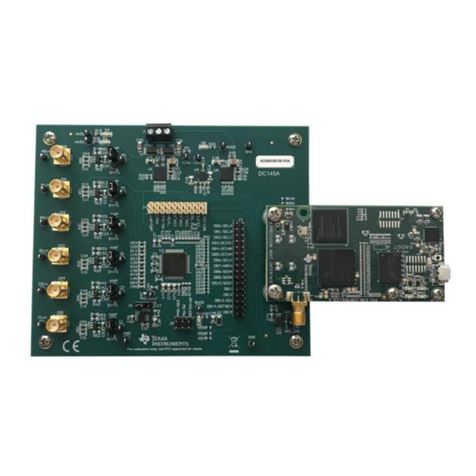
1 WL1835MODCOM8B Top View ........................................................................................... 3
2 Board Top View.............................................................................................................. 6
3 Board Bottom View.......................................................................................................... 6
4 Antenna VSWR............................................................................................................. 10
5 Antenna Efficiency ......................................................................................................... 11
6 Radio Pattern ............................................................................................................... 11
7 ANT1 Polarization.......................................................................................................... 12
8 ANT1 Polarization.......................................................................................................... 12
9 ANT1 Polarization.......................................................................................................... 13
10 ANT2 Polarization.......................................................................................................... 13
11 ANT2 Polarization.......................................................................................................... 14
12 ANT2 Polarization.......................................................................................................... 14
13 Schematic ................................................................................................................... 15
14 Layer 1....................................................................................................................... 17
15 Layer 2....................................................................................................................... 17
16 Layer 3....................................................................................................................... 18
