4.17 SPI Interface.................................................................................................................................................................. 48
5 References............................................................................................................................................................................ 49
5.1 Reference Documents..................................................................................................................................................... 49
5.2 Other TI Components Used in This Design..................................................................................................................... 49
6 Revision History................................................................................................................................................................... 49
A E3 Design Changes..............................................................................................................................................................50
List of Figures
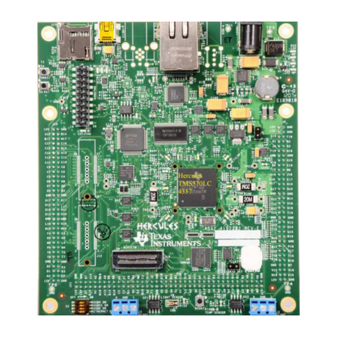
Figure 2-1. AM243x LaunchPad Board....................................................................................................................................... 4
Figure 2-2. System Architecture.................................................................................................................................................. 5
Figure 2-3. AM243x LaunchPad Top Component Identification.................................................................................................. 6
Figure 2-4. AM243x LaunchPad Bottom Component Identification.............................................................................................6
Figure 2-5. Security Field Parameter...........................................................................................................................................7
Figure 3-1. USB Type-C Power Delivery Classification............................................................................................................... 8
Figure 3-2. Type-C CC Configuration.......................................................................................................................................... 9
Figure 3-3. USB Type-C Power Input........................................................................................................................................ 10
Figure 3-4. Power Status LED's.................................................................................................................................................11
Figure 3-5. Power Tree Diagram of AM243x LaunchPad.......................................................................................................... 12
Figure 3-6. Power Sequence..................................................................................................................................................... 13
Figure 3-7. Boot-Mode DIP Switch............................................................................................................................................ 14
Figure 4-1. AM243x LaunchPad Functional Block Diagram...................................................................................................... 15
Figure 4-2. BoosterPack Header Pinout.................................................................................................................................... 16
Figure 4-3. Site #2 BoosterPack Header................................................................................................................................... 17
Figure 4-4. 80 Pin BoosterPack Pinout......................................................................................................................................18
Figure 4-5. Reset Architecture...................................................................................................................................................29
Figure 4-6. Clock Architecture................................................................................................................................................... 30
Figure 4-7. QSPI Interface.........................................................................................................................................................31
Figure 4-8. Board ID EEPROM..................................................................................................................................................32
Figure 4-9. Ethernet Connection................................................................................................................................................33
Figure 4-10. CPSW or PRG RGMII1 Ethernet Data Mux.......................................................................................................... 34
Figure 4-11. Ethernet PHY Strapping for RGMII1 PHY............................................................................................................. 35
Figure 4-12. Ethernet PHY Strapping for RGMII2 PHY............................................................................................................. 35
Figure 4-13. USB 2.0 Interface.................................................................................................................................................. 37
Figure 4-14. I2C Interface..........................................................................................................................................................37
Figure 4-15. Industrial Application LEDs................................................................................................................................... 38
Figure 4-16. UART Interface......................................................................................................................................................39
Figure 4-17. eQEP Interface......................................................................................................................................................40
Figure 4-18. eQEP1 Header...................................................................................................................................................... 40
Figure 4-19. eQEP2 Header...................................................................................................................................................... 41
Figure 4-20. eQEP2 or MCAN0 Mux Selection Circuit.............................................................................................................. 41
Figure 4-21. CAN Interface........................................................................................................................................................42
Figure 4-22. MCAN Transceiver and Header............................................................................................................................ 42
Figure 4-23. FSI Interface..........................................................................................................................................................43
Figure 4-24. FSI Header............................................................................................................................................................ 44
Figure 4-25. FSI or BoosterPack Mux Selection Circuit............................................................................................................ 44
Figure 4-26. JTAG Interface.......................................................................................................................................................45
Figure 4-27. Micro-B USB Connection for JTAG....................................................................................................................... 45
Figure 4-28. Test Automation Header........................................................................................................................................46
Figure 4-29. SPI Connection From SoC to BoosterPack Connector......................................................................................... 48
List of Tables
Table 3-1. Current Sourcing Capability and State of USB Type-C Cable.................................................................................. 10
Table 3-2. Power Status LED's.................................................................................................................................................. 10
Table 3-3. LaunchPad Push Buttons......................................................................................................................................... 13
Table 3-4. Boot-Mode Selection Table ...................................................................................................................................... 14
Table 4-1. BoosterPack Power Sourcing for BoosterPack Site #2............................................................................................ 17
Table 4-2. Pinmux Legend......................................................................................................................................................... 19
Table 4-3. Pinmux Options for J1 Connector - Site 1.................................................................................................................19
Table 4-4. Pinmux Options for J2 Connector - Site 1.................................................................................................................20
Table 4-5. Pinmux Options for J3 Connector - Site 1.................................................................................................................20
Table 4-6. Pinmux Options for J4 Connector - Site 1.................................................................................................................20
Table 4-7. Net Name in Schematic and Package Signal Name for J1/J3 Connector................................................................ 21
Table of Contents www.ti.com
2AM243x LaunchPad™ Development Kit User's Guide SPRUJ12D – AUGUST 2021 – REVISED APRIL 2023
Submit Document Feedback
Copyright © 2023 Texas Instruments Incorporated
