manuals.online logo
Brands
  1. Home
  2. •
  3. Brands
  4. •
  5. Texas Instruments
  6. •
  7. Motherboard
  8. •
  9. Texas Instruments UCC25640EVM-020 User manual

Texas Instruments UCC25640EVM-020 User manual

UCC25640EVM-020 Evaluation Module
User's Guide
Literature Number: SLUUBX3B
June 2019–Revised November 2019
WARNING
www.ti.com
2SLUUBX3B–June 2019–Revised November 2019
Submit Documentation Feedback
Copyright © 2019, Texas Instruments Incorporated
General Texas Instruments High Voltage Evaluation (TI HV EMV) User Safety Guidelines
Always follow TI's set-up and application instructions, including use of all interface components within their
recommended electrical rated voltage and power limits. Always use electrical safety precautions to help
ensure your personal safety and those working around you. Contact TI's Product Information Center
http://ti.com/customer support for further information.
Save all warnings and instructions for future reference.
WARNING
Failure to follow warnings and instructions may result in personal injury,
property damage or death due to electrical shock and burn hazards.
The term TI HV EVM refers to an electronic device typically provided as an open framed, unenclosed
printed circuit board assembly. It is intended strictly for use in development laboratory environments,
solely for qualified professional users having training, expertise and knowledge of electrical safety risks in
development and application of high voltage electrical circuits. Any other use and/or application are strictly
prohibited by Texas Instruments. If you are not suitable qualified, you should immediately stop from further
use of the HV EVM.
1. Work Area Safety:
a. Keep work area clean and orderly.
b. Qualified observer(s) must be present anytime circuits are energized.
c. Effective barriers and signage must be present in the area where the TI HV EVM and its interface
electronics are energized, indicating operation of accessible high voltages may be present, for the
purpose of protecting inadvertent access.
d. All interface circuits, power supplies, evaluation modules, instruments, meters, scopes, and other
related apparatus used in a development environment exceeding 50Vrms/75VDC must be
electrically located within a protected Emergency Power Off EPO protected power strip.
e. Use stable and non-conductive work surface.
f. Use adequately insulated clamps and wires to attach measurement probes and instruments. No
freehand testing whenever possible.
2. Electrical Safety:
As a precautionary measure, it is always good engineering practice to assume that the entire EVM
may have fully accessible and active high voltages.
a. De-energize the TI HV EVM and all its inputs, outputs and electrical loads before performing any
electrical or other diagnostic measurements. Revalidate that TI HV EVM power has been safely
de-energized.
b. With the EVM confirmed de-energized, proceed with required electrical circuit configurations,
wiring, measurement equipment hook-ups and other application needs, while still assuming the
EVM circuit and measuring instruments are electrically live.
c. Once EVM readiness is complete, energize the EVM as intended.
www.ti.com
3
SLUUBX3B–June 2019–Revised November 2019
Submit Documentation Feedback Copyright © 2019, Texas Instruments Incorporated
WARNING
While the EVM is energized, never touch the EVM or its electrical
circuits, as they could be at high voltages capable of causing
electrical shock hazard.
3. Personal Safety
a. Wear personal protective equipment e.g. latex gloves or safety glasses with side shields or protect
EVM in an adequate lucent plastic box with interlocks from accidental touch.
Limitation for safe use:
EVMs are not to be used as all or part of a production unit.
4SLUUBX3B–June 2019–Revised November 2019
Submit Documentation Feedback
Copyright © 2019, Texas Instruments Incorporated
UCC25640EVM-020 Evaluation Module
User's Guide
SLUUBX3B–June 2019–Revised November 2019
UCC25640EVM-020 Evaluation Module
1 Introduction
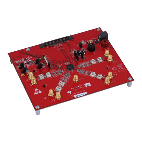
The purpose of the UCC25640EVM-020 (EVM) is to aid in evaluation of the UCC256403 and UCC256404
LLC resonant controller. The EVM is a stand-alone LLC resonant half-bridge DC-DC power converter
designed to operate with DC input from 365 VDC to 410 VDC, AC input from 85 to 265 VRMS, 47 to 63 Hz,
and a nominal output of 12 VDC up to 180-W. The EVM is delivered using a diode rectifier at the output.
The user has the option to evaluate this converter with a synchronous rectifier (SR) by populating the
UCC24624 and SR FETs. This user’s guide provides basic evaluation instruction from a viewpoint of
system operation of the stand-alone LLC resonant power converter.
Figure 1. UCC25640EVM-020 Top View
Figure 2. UCC25640EVM-020 Side View
www.ti.com
Description
5
SLUUBX3B–June 2019–Revised November 2019
Submit Documentation Feedback Copyright © 2019, Texas Instruments Incorporated
UCC25640EVM-020 Evaluation Module
2 Description
2.1 Typical Applications
• SMPS power supply for TV
• Industrial AC-DC adapters
• Power tools
• Medical power supply
• Multi-functional printer
• Enterprise and cinema projector
• PC power supply
• Gaming console power supply
• Lighting
2.2 Features
• Hybrid hysteretic controlled LLC resonant half-bridge DC-DC power conversion
• DC line Input from 365 VDC to 410 VDC
• AC Input voltage from 85 VDC to 265 VAC
• Regulated 12-VDC typical output
• Regulated 9.75-VDC low power mode output
• Full-load power of 180 W, or full-load current of 15 A
• High efficiency
• Optimized low power features enable extremely low standby power
• Advanced burst mode with burst soft-on and soft-off for minimized audible noise
• Adaptive dead-time
• X-capacitor discharge
• Over temperature, output over voltage, and three level over current protections
• Test points to facilitate device and topology evaluation
2.3 Using the EVM with UCC256402
• Replace U4 with UCC256402
• Replace R37 with 124kΩ
• Connect TP1 to TP14
• Disconnect the AC voltage source
2.4 Using the EVM with UCC256403
UCC25640EVM-020 comes populated with UCC256404. To use this EVM with UCC256403:
• Replace U4 with UCC256403
• Remove R5 and R28
• Replace R37 with 124 kΩ
• Remove C25
• Replace R57 with 1.07kΩ
• Replace C46 with 2.2nF
• Replace C36 with 33 nF
• Connect a 15 V DC source to TP6
• Disconnect the AC voltage source
Description
www.ti.com
6SLUUBX3B–June 2019–Revised November 2019
Submit Documentation Feedback
Copyright © 2019, Texas Instruments Incorporated
UCC25640EVM-020 Evaluation Module
2.5 Using the EVM with UCC24624 Synchronous Rectifier Controller
UCC25640EVM-020 is delivered using the diode rectifier at the output. The option to evaluate the
converter with synchronous rectification (SR) is available to the user. SR is often used to increase
efficiency by replacing the freewheeling diode with a lower loss FET.
To use this EVM with UCC24624:
• Remove D2 and D5
• Populate R31 and R32 with 0Ω
• Populate R35 with 10Ω
• Populate R53 and R54 with 532Ω
• Populate R55 with 39.2Ω
• Populate R2 and R7 with 10Ω
• Populate C2 and C19 with 1.2nF
www.ti.com
Performance Specifications
7
SLUUBX3B–June 2019–Revised November 2019
Submit Documentation Feedback Copyright © 2019, Texas Instruments Incorporated
UCC25640EVM-020 Evaluation Module
3 Performance Specifications
Table 1. UCC25640EVM-020 Specifications
PARAMETER TEST CONDITIONS MIN TYP MAX UNITS
INPUT CHARACTERISTICS
DC voltage range 365 390 410 VDC
AC voltage range 85 265 VAC
AC voltage frequency 47 63 Hz
Input DC UVLO On 365 VDC
Input DC UVLO Off 330 VDC
OUTPUT CHARACTERISTICS
VOUT Output voltage - Normal mode Burst mode threshold to full load =
15 A 12 VDC
VOUT Output voltage - Standby mode No load to burst mode threshold 9.75 VDC
Burst mode threshold output
current limit (rising) 240 mA
Burst mode threshold output
current limit (falling) 110 mA
IOUT Output load current 365 to 410 VDC 15 A
Output voltage ripple 390 VDC and full load = 15 A 120 mVpp
SYSTEM CHARACTERISTICS
Resonant frequency 100 kHz
Peak efficiency 390 VDC, load = 8 A 93%
Operating temperature Natural convection 25 ºC
Schematic Diagram
www.ti.com
8SLUUBX3B–June 2019–Revised November 2019
Submit Documentation Feedback
Copyright © 2019, Texas Instruments Incorporated
UCC25640EVM-020 Evaluation Module
4 Schematic Diagram
Figure 3. UCC25640EVM-020 Power Stage Schematic
www.ti.com
Schematic Diagram
9
SLUUBX3B–June 2019–Revised November 2019
Submit Documentation Feedback Copyright © 2019, Texas Instruments Incorporated
UCC25640EVM-020 Evaluation Module
Figure 4. UCC25640EVM-020 Control Schematic
Test Setup
www.ti.com
10 SLUUBX3B–June 2019–Revised November 2019
Submit Documentation Feedback
Copyright © 2019, Texas Instruments Incorporated
UCC25640EVM-020 Evaluation Module
5 Test Setup
5.1 Test Equipment
DC Voltage Source: Capable of 365 VDC to 410 VDC, adjustable, with minimum power rating 500 W, or
current rating not less than 1 A, with current limit function. The DC voltage source to be used should meet
IEC 60950 reinforced insulation requirement.
AC Voltage Source: Capable of single-phase output AC voltage 85 to 265 VAC, 47 to 63 Hz, adjustable,
with minimum power rating 100 W and current limit function. The AC voltage source to be used should
meet IEC 60950 reinforced insulation requirement.
DC Digital Multimeter: One unit capable of 0-VDC to 450-VDC input range, four digit display preferred;
and one unit capable of 0-VDC to 20-VDC input range, four digit display preferred.
Output Load: : DC load capable of receiving 0 VDC to 20 VDC, 0 A to 15 A, and 0 W to 300 W or
greater, with the capability to display information such as load current and load power.
Oscilloscope: Capable of 500-MHz full bandwidth, digital or analog: if digital, 5 Gsps, or better.
Fan: 200 to 400 LFM forced air cooling is recommended, but not required.
Recommended Wire Gauge: Capable of 25 A, or better than #14 AWG, with the total length of wire less
than 8 feet (4 feet input and 4 feet return).
www.ti.com
Test Setup
11
SLUUBX3B–June 2019–Revised November 2019
Submit Documentation Feedback Copyright © 2019, Texas Instruments Incorporated
UCC25640EVM-020 Evaluation Module
5.2 Recommended Test Setup
Figure 5. UCC25640EVM-020 Test Setup Diagram
WARNING
High voltages that may cause injury exist on this evaluation
module (EVM). Please ensure all safety procedures are followed
when working on this EVM. Never leave a powered EVM
unattended.
Test Setup
www.ti.com
12 SLUUBX3B–June 2019–Revised November 2019
Submit Documentation Feedback
Copyright © 2019, Texas Instruments Incorporated
UCC25640EVM-020 Evaluation Module
5.3 Power Factor Correction (PFC) Boost Front End Setup
UCC25640EVM-020 is typical for a two stage AC/DC power supply with a PFC boost converter in front of
it. The following steps and schematic describe how to connect the UCC28056EVM-296 or
UCC28064EVM-004, Transition-Mode (TM) PFC Controllers, to this EVM.
1. Remove D8 and D9 from UCC25640EVM-020.
2. Connect the anode of D8 to AC Line and the anode of D9 to AC Neutral on UCC28056EVM-296 or
UCC28064EVM-004.
3. Connect both the cathodes of D8 and D9 to TP14 on UCC25640EVM-020.
4. Connect TP15 (RVCC) on UCC25640EVM-020 to TP9 (VCC) on UCC28056EVM-296 or J1-1 (VCC)
on UCC28064EVM-004.
Figure 6 is a diagram of the PFC LLC setup used for testing.
Figure 6. UCC28056EVM-296/UCC28064EVM-004 PFC to UCC25640EVM-020 LLC Test Setup
www.ti.com
Test Points
13
SLUUBX3B–June 2019–Revised November 2019
Submit Documentation Feedback Copyright © 2019, Texas Instruments Incorporated
UCC25640EVM-020 Evaluation Module
6 Test Points
Table 2 lists the EVM test points.
Table 2. Test Points
Test Points Name Description
TP1 VIN Input voltage positive terminal
TP2 HO Primary-side high side MOSFET gate, Q1
TP3 SGND Secondary-side ground
TP4 SGND Secondary-side ground
TP5 HS Primary-side switch node, or the intersection of Q1
and Q3
TP6 VCC Supply input
TP7 LO Primary-side low side MOSFET gate, Q3
TP8 PGND Primary-side ground
TP9 PGND Primary-side ground
TP10 VOUT Output voltage positive terminal
TP11 INJECT Small signal injection terminal
TP12 FB_Current Feedback current measurement
TP13 HV High-voltage start pin
TP14 AC_Rect Rectified AC input
TP15 RVCC Regulated 12-V supply
TP16 BLK Input voltage sensing
TP17 AC_L AC line
TP18 AC_N AC neutral
TP19 LL/SS Soft-start and light-load burst mode threshold
TP20 ISNS Resonant current sense
TP21 BW Bias winding voltage sense
TP22 VCR Resonant capacitor voltage sense
7 Terminals
Table 3 lists the EVM terminals.
Table 3. List of Terminals
Terminal Name Description
J1 VIN Input voltage positive terminal
J2 PGND Input voltage return terminal
J8 AC Input 3-pin, AC power input, 85–265 VRMS
T2 VOUT Output voltage positive terminal
T3 SGND Output voltage ground terminal
Test Procedure
www.ti.com
14 SLUUBX3B–June 2019–Revised November 2019
Submit Documentation Feedback
Copyright © 2019, Texas Instruments Incorporated
UCC25640EVM-020 Evaluation Module
8 Test Procedure
Use the following steps for the test procedure:
1. Refer to Section 5.2 for basic setup. The required equipment for this measurement is listed in
Section 5.1.
2. Before making electrical connections, visually check the board to make sure there are no suspected
spots of damage.
3. Keep the DC voltage source output off. Connect the DC source to J1 (+) and J2 (-). The DC voltage
source should be isolated and meet the IEC 60950 requirement. Set the DC output voltage within the
range specified in Table 1, between 365 VDC and 410 VDC; set the DC source current limit to 1 A.
CAUTION
The board has no fuse installed and relies on the external voltage source
current limit to ensure circuit protection.
4. Keep the AC voltage source output off. Connect the source with AC_neutral to J8-1, AC_earth to J8-2,
and AC_line to J8-3. Isolate the AC voltage source and meet the IEC 60950 requirement. Set the AC
output voltage and frequency within the range specified in Table 1, between 85 and 265 VAC and 47
to 63 Hz. Set the AC source current limit to 200 mA.
5. Connect an electronic load set to either constant-current mode or constant-resistance mode. The load
range is from 0 to 15 A.
6. If the load does not have a current or a power display, TI recommends inserting a current meter
between the output voltage and the electronic load.
7. Connect a voltage meter to TP10 and TP3/TP4 to monitor the output voltage.
8. Turn on the AC source output.
9. Turn on the DC source output.
8.1 Equipment Shutdown
Shut down the equipment using the following steps:
1. Shut down the AC voltage source.
2. Shut down the DC voltage source.
3. Shut down the electronic load.
WARNING
High voltage may still be present on the resonant capacitors after
turning off the DC source.
www.ti.com
Performance Data and Typical Characteristic Curves
15
SLUUBX3B–June 2019–Revised November 2019
Submit Documentation Feedback Copyright © 2019, Texas Instruments Incorporated
UCC25640EVM-020 Evaluation Module
9 Performance Data and Typical Characteristic Curves
9.1 UCC25640EVM-020 Standalone Standby and Light Load Power
Table 4 lists the total standby and light load power measurement for the standalone EVM. The average
input power is measured over a two minute interval.
Table 4. Standalone Standby Power
IOUT (mA) VOUT (V) POUT (mW) VIN (V) IIN (mA) PIN (mW)
0 9.740 0.000 389.826 0.115 44.666
10 9.739 97.392 389.823 0.393 153.093
20 9.739 194.772 389.820 0.672 261.815
50 9.739 486.925 389.814 1.514 590.186
100 9.738 973.820 389.807 2.914 1135.799
9.2 PFC Boost Front End Standby Power
9.2.1 Overview
UCC256404 includes a high voltage startup feature. This feature enables the controller to be powered by
a wide AC input, eliminating the need for an external supply to power both the PFC and LLC. When AC
power is applied to UCC256404, a JFET initially charges the VCC capacitor to provide the energy needed
to start the PFC and LLC power system. Once running, power for the PFC and LLC controllers is derived
from a bias winding on the LLC transformer. Figure 7 illustrates the described startup sequence.
UCC256403 does not include the high voltage startup feature and requires an external power supply as
described in Section 5.3.
Figure 7. PFC LLC Startup Sequence
Performance Data and Typical Characteristic Curves
www.ti.com
16 SLUUBX3B–June 2019–Revised November 2019
Submit Documentation Feedback
Copyright © 2019, Texas Instruments Incorporated
UCC25640EVM-020 Evaluation Module
9.2.2 PFC LLC Standby Power and Light Load Efficiency
PFC LLC system standby power for UCC25640EVM-020 is measured with both UCC28056EVM-296 and
UCC28064EVM-004. Refer to Section 5.3 for test setup and procedure. The WT310 power analyzer is
used for PFC LLC standby and light load measurements.
Table 5. Total Standby Power with UCC28056EVM-296 (PFC) and UCC25640EVM-020 (LLC)
VIN (V) PIN (W) VOUT (V) IOUT (A) POUT (W) Efficiency (%)
90 0.218 9.697 0.0124 0.120 54.94
115 0.216 9.697 0.0124 0.120 55.44
230 0.223 9.697 0.0124 0.120 53.70
265 0.227 9.697 0.0124 0.120 52.76
90 0.361 9.697 0.0248 0.240 66.56
115 0.360 9.696 0.0248 0.240 66.74
230 0.364 9.697 0.0248 0.240 66.01
265 0.365 9.697 0.0248 0.240 65.83
Table 6. Total Standby Power with UCC28064EVM-004 (PFC) and UCC25640EVM-020 (LLC)
VIN (V) PIN (W) VOUT (V) IOUT (A) POUT (W) Efficiency (%)
90 0.229 9.697 0.0124 0.120 52.29
115 0.228 9.696 0.0124 0.120 52.52
230 0.250 9.697 0.0124 0.120 47.90
265 0.260 9.697 0.0124 0.120 46.06
90 0.374 9.696 0.0248 0.240 64.24
115 0.370 9.696 0.0248 0.240 64.94
230 0.391 9.696 0.0248 0.240 61.45
265 0.400 9.696 0.0248 0.240 60.07
9.3 Efficiency
Figure 8 illustrates the standalone EVM efficiency graph.
Figure 8. Efficiency vs Output Current
www.ti.com
Performance Data and Typical Characteristic Curves
17
SLUUBX3B–June 2019–Revised November 2019
Submit Documentation Feedback Copyright © 2019, Texas Instruments Incorporated
UCC25640EVM-020 Evaluation Module
9.4 Load Regulation
Figure 9 illustrates the load regulation versus output current graph.
Figure 9. Load Regulation vs Output Current
9.5 Switching Frequency
Figure 10 illustrates the converter switching frequency versus output current.
Figure 10. Switching Frequency vs Output Current
Performance Data and Typical Characteristic Curves
www.ti.com
18 SLUUBX3B–June 2019–Revised November 2019
Submit Documentation Feedback
Copyright © 2019, Texas Instruments Incorporated
UCC25640EVM-020 Evaluation Module
9.6 Audible Noise
Figure 11 and Figure 12 show the audible noise measurements during light load standby operation. The
measurements are performed in a soundproof container with the microphone 5 mm above the transformer.
Figure 11. Audible Noise Measurement at 10 mA Load
Figure 12. Audible Noise Measurement at 20 mA Load
www.ti.com
Performance Data and Typical Characteristic Curves
19
SLUUBX3B–June 2019–Revised November 2019
Submit Documentation Feedback Copyright © 2019, Texas Instruments Incorporated
UCC25640EVM-020 Evaluation Module
9.7 Startup
The following waveforms show the output voltage and low side gate behavior. 115 VAC, 60 Hz is applied
initially to the AC input, then the 390 VDC input is applied to the DC input
Figure 13. No Load (0 A) Startup (Ch2 = VOUT; Ch3 = LO)
Figure 14. Full Load (15 A) Startup (Ch2 = VOUT; Ch3 = LO)
Performance Data and Typical Characteristic Curves
www.ti.com
20 SLUUBX3B–June 2019–Revised November 2019
Submit Documentation Feedback
Copyright © 2019, Texas Instruments Incorporated
UCC25640EVM-020 Evaluation Module
9.8 Thermal Image
The following images show the EVM temperature after 20min soak at full load, no forced air and 390Vdc
input applied to the DC input.
Figure 15. Thermal Image Top
Table 7. Component Temperature
Component Temperature (°C)
T1 (Bx1) 74.9°C
D2 (Bx2) 90.2°C
Figure 16. Thermal Image Bottom
Table 8. Component Temperature
Component Temperature (°C)
U4 (Bx1) 42.3°C
Q1 (Bx2) 44.9°C
Q3 (Bx3) 46.1°C
R9, R12 (Bx4) 72.2°C

Other Texas Instruments Motherboard manuals

Texas Instruments DLPC4430EVM User manual

Texas Instruments

Texas Instruments DLPC4430EVM User manual

Texas Instruments TAS5708EVM User manual

Texas Instruments

Texas Instruments TAS5708EVM User manual

Texas Instruments THS4503EVM User manual

Texas Instruments

Texas Instruments THS4503EVM User manual

Texas Instruments TAS2572 User manual

Texas Instruments

Texas Instruments TAS2572 User manual

Texas Instruments LP8756 Q1EVM Series User manual

Texas Instruments

Texas Instruments LP8756 Q1EVM Series User manual

Texas Instruments bq27425EVM User manual

Texas Instruments

Texas Instruments bq27425EVM User manual

Texas Instruments TPS54386EVM User manual

Texas Instruments

Texas Instruments TPS54386EVM User manual

Texas Instruments TMP392EVM User manual

Texas Instruments

Texas Instruments TMP392EVM User manual

Texas Instruments DAC8775EVM User manual

Texas Instruments

Texas Instruments DAC8775EVM User manual

Texas Instruments DS90UB95x-Q1EVM Series User manual

Texas Instruments

Texas Instruments DS90UB95x-Q1EVM Series User manual

Texas Instruments LMK04208 User manual

Texas Instruments

Texas Instruments LMK04208 User manual

Texas Instruments DRV2605EVM-CT User manual

Texas Instruments

Texas Instruments DRV2605EVM-CT User manual

Texas Instruments DLP LightCrafter Display 4710 User manual

Texas Instruments

Texas Instruments DLP LightCrafter Display 4710 User manual

Texas Instruments INA220EVM User manual

Texas Instruments

Texas Instruments INA220EVM User manual

Texas Instruments DAC7741EVM User manual

Texas Instruments

Texas Instruments DAC7741EVM User manual

Texas Instruments UCC25630-1EVM-291 User manual

Texas Instruments

Texas Instruments UCC25630-1EVM-291 User manual

Texas Instruments bq2415x User manual

Texas Instruments

Texas Instruments bq2415x User manual

Texas Instruments TRF4903 User manual

Texas Instruments

Texas Instruments TRF4903 User manual

Texas Instruments DAC39RF10EVM User manual

Texas Instruments

Texas Instruments DAC39RF10EVM User manual

Texas Instruments SN75LVCP600S User manual

Texas Instruments

Texas Instruments SN75LVCP600S User manual

Texas Instruments ADS8900BEVM-PDK User manual

Texas Instruments

Texas Instruments ADS8900BEVM-PDK User manual

Texas Instruments INA193EVM User manual

Texas Instruments

Texas Instruments INA193EVM User manual

Texas Instruments TPA3220 User manual

Texas Instruments

Texas Instruments TPA3220 User manual

Texas Instruments bq24720 EVM User manual

Texas Instruments

Texas Instruments bq24720 EVM User manual

Popular Motherboard manuals by other brands

Albatron PM945GC user manual

Albatron

Albatron PM945GC user manual

Moxa Technologies CI-104J Series Quick installation guide

Moxa Technologies

Moxa Technologies CI-104J Series Quick installation guide

Advantech SOM-6868 manual

Advantech

Advantech SOM-6868 manual

Asus prime B250M-K quick start guide

Asus

Asus prime B250M-K quick start guide

GIGA-BYTE TECHNOLOGY H410M DS2V V2 user manual

GIGA-BYTE TECHNOLOGY

GIGA-BYTE TECHNOLOGY H410M DS2V V2 user manual

Gigabyte GA-990XA-UD3 R5 user manual

Gigabyte

Gigabyte GA-990XA-UD3 R5 user manual

DFI G486VPA user manual

DFI

DFI G486VPA user manual

Lanner electronics AP-687VF manual

Lanner electronics

Lanner electronics AP-687VF manual

Giada Mini-ITX user manual

Giada

Giada Mini-ITX user manual

VIA Technologies EPIA-M850 operating guide

VIA Technologies

VIA Technologies EPIA-M850 operating guide

ASROCK Z77 Extreme9 user manual

ASROCK

ASROCK Z77 Extreme9 user manual

Abit SL6 user manual

Abit

Abit SL6 user manual

DFI CR100-CRM user manual

DFI

DFI CR100-CRM user manual

JETWAY 695AS user manual

JETWAY

JETWAY 695AS user manual

Advantech AIMB-740 Series user manual

Advantech

Advantech AIMB-740 Series user manual

MSI MS-7235 user guide

MSI

MSI MS-7235 user guide

Gigabyte GA-P35-DS4 user manual

Gigabyte

Gigabyte GA-P35-DS4 user manual

JETWAY MM10-H6100 Technical manual

JETWAY

JETWAY MM10-H6100 Technical manual

manuals.online logo
manuals.online logoBrands
  • About & Mission
  • Contact us
  • Privacy Policy
  • Terms and Conditions

Copyright 2025 Manuals.Online. All Rights Reserved.