Texecom Premier Elite iProx User manual

Installation Manual
Premier Elite iProx
INS303-5
Intelligent Proximity Module

14-10-2022 • Updated drawing in section % to correct the cable length for external prox, and add a note to not extend the cable.

INS303-5 3/22
Content
1.0 Introduction 4 ............................................................................................................................
1.1 Network Mode 4 .....................................................................................................................
1.2 Stand-alone Mode 4 ................................................................................................................
2.0 PCB Layout 5 ..............................................................................................................................
3.0 Network Mode Installation 6 ...................................................................................................
3.1 Introduction 6 .........................................................................................................................
3.2 Option and Address Switches for Network Mode 7 .................................................................
3.3 Using Premier Elite Proximity Tags 7 ......................................................................................
3.4 Using 3rd Party Proximity Tags 9 ...........................................................................................
4.0 Using the Key Seven SA840-A20 Keypad 11 .........................................................................
5.0 Installing a Premier Elite External Prox 13 ...........................................................................
6.0 Stand-alone Mode Installation 14 ...........................................................................................
6.1 Introduction 14 .......................................................................................................................
6.2 Option Switches for Network Mode 14 ....................................................................................
6.3 Using Premier Proximity Tags 15 ............................................................................................
6.4 Using 3rd Party Proximity Tags 18 .........................................................................................
6.5 Stand-alone Mode Operation 20 .............................................................................................
7.0 Specifications 20 ........................................................................................................................
8.0 Standards 21 ..............................................................................................................................
9.0 Warranty 22 ................................................................................................................................

INS303-5 4/22
1.0 Introduction
The Premier Elite iProx module can be installed in one of two modes:
1.1 Network Mode
The network mode allows the Premier iProx to be connected to the network
terminals of the Premier Elite 24,48,88,168,640 control panels. This mode provides
the following facilities:
Built in proximity reader using standard Premier Elite proximity tags
Connections for optional external reader Premier Elite External Prox
26bit Wiegand interface to allow support for 3rd party access control readers
Support for Key Seven SA840-A20 keypad
Proximity tags/user codes are stored in the control panel
Request To Exit (RTE) input
Voltage free contacts (3 Amps) for connection to door strike
Internal sounder and extension loudspeaker connections
Can be used as an arming station or as door access only.
Standard 7/0.2 alarm cable can be used for most installations. However,
under certain conditions it may be necessary to use screened cable.
N The maximum number of tags/users codes that can be stored is dependent on
the number of users available on the control panel.
1.2 Stand-alone Mode
The stand-alone mode allows the Premier Elite iProx to be used as a simple door
access controller. This mode provides the following facilities:
Built in proximity reader using standard Premier proximity tags
Connections for optional external reader Premier External Prox
26bit Wiegand interface to allow support for 3rd party access control readers
Up to 10 proximity tags can be stored in the module

INS303-5 5/22
Request To Exit (RTE) input
Voltage free contacts (3 Amps) for connection to door strike
Internal sounder and extension loudspeaker connections
2.0 PCB Layout
Extension loudspeaker terminals (16 Ohm)1.
Wiegand interface connections2.
Network terminals for connection to a control panel (Network Mode)3.
Status LED4.
Tamper switch connector5.

INS303-5 6/22
Volume adjustment for extension loudspeaker6.
Remote proximity coil and LED terminal connections for Premier External7.
Prox unit
Internal proximity coil8.
Request To Exit (RTE) input (apply 0V to activate)9.
Door strike relay (voltage free change-over contacts)10.
Address/User/Door Strike time selection switches11.
Option selection switches12.
Enable/disable internal sounder jumper link13.
Internal/External coil selection jumper links14.
3.0 Network Mode Installation
3.1 Introduction
When the iProx is used in the Network mode, it uses one of the available remote
keypad address slots on the system. The maximum number of keypad address
slots varies depending on the control panel:
Before installing the unit, make sure that you have a spare keypad address slot, if
all keypad slots have been used it will not be possible to install the iProx in this
mode.

INS303-5 7/22
3.2 Option and Address Switches for Network
Mode
When installed in this mode the Option and Address switches function as follows:
3.3 Using Premier Elite Proximity Tags
This configuration allows you to use the standard proximity tags that are used with
the Premier & Premier Elite keypads. The tags MUST be learnt at a keypad which
has a built in proximity reader. The figure below shows a typical installation:

INS303-5 8/22
Installation
Remove all power from control panel before making any connections.
Install the module in the required location making sure that it is mounted1.
away from metal objects and other cables as these can affect the
performance of the unit.
Connect the network connections of the module to the network connections2.
of the control panel.
Connect the optional devices such the door strike, RTE button and3.
loudspeaker.
Set the Internal/External coil jumper links 14 to Internal (Int).4.
Ensure that Options switch 1 is set to ON (Internal Prox. Enabled) and5.
switches 2, 3 and 4 are set as required, (see chapter 3.1)
Using Address switches set the address of the module to one of the6.
available keypad address slots, (see chapter 3.1).
Re-apply power to the control panel and select the engineer’s programming7.
mode.
Select the “Confirm Devices” option within the “Engineer Utils” menu and8.
confirm that the module is being “seen” as a remote keypad on the system.
If the relay on the iProx is utilized, it is controlled by the relevant remote9.
keypad output. Select the “Keypad Outputs” option within the “System
Outputs” menu and program it to the required type, e.g. “Door Strike”.
If required learn any new tags then exit the engineer’s mode.10.
Check that the iProx and proximity tags operate correctly.11.

INS303-5 9/22
Learning Premier Elite Proximity Tags
If the system is already using Premier proximity tags then the existing tags will
work as normal when presented to the iProx module. For full details on learning
proximity tags refer to the control panel installation manual.
3.4 Using 3rd Party Proximity Tags
This configuration allows you to use proximity tags from other manufacturers. The
proximity reader MUST be capable of providing the data in 26bit Wiegand format.
The figure below shows a typical installation:
Installation
Remove all power from control panel before making any connections.
Install the 26bit Wiegand reader in the required location and according to the1.
manufacturer’s instructions.
Install the iProx module at least 0.5 metre away from the 26bit Wiegand2.
reader and from other metal objects and cables.
Connect the network connections of the module to the network connections3.
of the control panel.
Connect 26bit Wiegand reader to the iProx as shown above.4.
Connect the optional devices such the door strike, RTE button and speaker.5.
Ensure that Options switch 1 is set to OFF (Internal Prox. Disabled) and6.
switches 2, 3 and 4 are set as required, (see chapter 3.1)

INS303-5 10/22
Using the Address switches, set the address of the module to one of the7.
available remote keypad address slots, (see chapter 3.1)
Re-apply power to the control panel and select the engineer’s programming8.
mode.
Select the “Confirm Devices” option within the “Engineer Utils” menu and9.
confirm that the module is being “seen” as a remote keypad on the system.
If the relay on the iProx is utilized, it is controlled by the relevant keypad10.
output. Select the “Keypad Outputs” option within the “System Outputs”
menu and program it to the required type, e.g. “Door Strike”.
Learn any new tags (see below) then exit the engineer’s mode.11.
Check that the iProx and proximity tags operate correctly.12.
Learning 3rd Party Tags on the Premier Elite 24/48/88/168/640
When using 3rd party tags via a Wiegand reader, the tag or card is encoded with a
unique 6 digit code. This code is learnt onto the control panel and is stored
separately from the user code, this allows for users to have a tag and access code
with different codes. To learn 3rd party tags proceed as follows:
Select the “Setup Users” menu on the control panel.1.
Enter the user number that you want to assign the tag or card.2.
Press [Yes] and program the user code and options as required, when the3.
remote keypad displays “Add TAG to User?”. Press [2] to select Import TAG.
The remote keypad will now display “IMPORTING TAG Present TAG Now”.4.
Present the tag or card to the Wiegand reader, you will hear an acceptance5.
tone when the tag is imported successfully.
Repeat steps 2 - 5 for other tags or cardsNetwork Mode Operation6.
When installed in the Network mode, the operation of the iProx is as
follows:
When a valid proximity tag is presented to the module or via the Wiegand
reader you will hear a beep from the internal sounder (if the Internal Sounder
jumper is set to ON). The status LED will momentarily change from green to
yellow indicating a valid tag read. If the alarm system is in a disarmed state

INS303-5 11/22
the control panel will start the exit sequence. The exit tone will be generated
if the “Sounder Enabled” switch 3 is ON. The user should leave premises as
normal. If the alarm system is armed or in entry mode the system will disarm
on presentation of a valid tag.
When an invalid proximity tag is presented to the module or via the Wiegand
reader you will hear a beep from the internal sounder (if the Internal Sounder
jumper is set to ON). The status LED will momentarily change from green to
yellow, but the status of the alarm is not affected.
The Door Strike relay is controlled by the control panel and will activate when
the relevant remote keypad output is active.
If the RTE input is activated the Door Strike relay is activated for 5 seconds.
N To restrict operation of the iProx to door strike please see the control panel
installation manual.
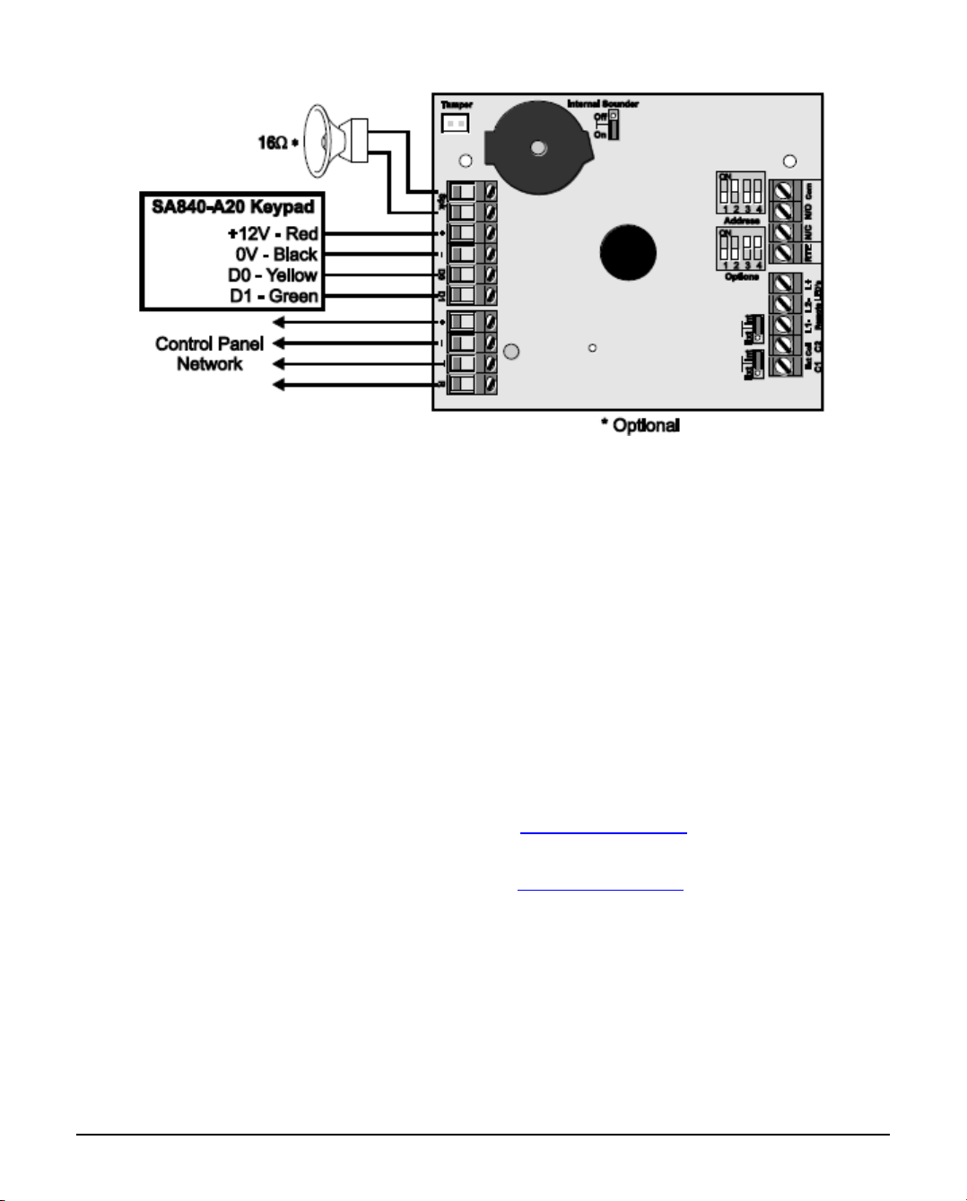
4.0 Using the Key Seven SA840-A20
Keypad
This configuration allows you to integrate the SA840-A20 keypad manufactured by
Key Seven with the Premier Elite 24/48/88/168/640 control panels. The figure
below shows a typical installation:
INS303-5 12/22
Installation
Remove all power from control panel before making any connections.
Install the SA840-A20 keypad in the required location and according to the1.
manufacturer’s instructions.
Program the SA840-A20 output format for Wiegand (format No 2).2.
Install the iProx module at least 0.5 metre away from other metal objects and3.
cables.
Connect the network connections of the module to the network connections4.
of the control panel.
Connect SA840-A20 keypad to the iProx as shown above.5.
Ensure that Options switch 1 is set to OFF (Internal Prox. Disabled) and6.
switches 2, 3 and 4 are set as required, (see chapter 3.1)
Using the Address switch set the address of the module to one of the7.
available remote keypad address slots, (see chapter 3.1)
Re-apply power to the control panel and select the engineer’s programming8.
mode.
Select the “Confirm Devices” option within the “Engineer Utils” menu and9.
confirm that the module is being “seen” as a remote keypad on the system.
If the relay on the iProx is utilized, it is controlled by the relevant keypad10.
output. Select the “Keypad Outputs” option within the “System Outputs”
menu and program it to the required type.

INS303-5 13/22
Setup user codes as required then exit the engineer’s mode.11.
Check that the SA840-A20 operate correctly.12.
SA840-A20 Keypad Operation
When the Premier iProx is installed with an SA840-A20 keypad the operation of the
alarm system is as follows:
If a valid user code is entered followed by the [P] key during the exit
sequence the remaining exit time is truncated and the system arms
immediately.
If a valid user code is entered followed by the [P] key whilst the system is
armed, the entry timer is started. The user must enter the premises via the
designated entry route and disarm the system using the standard Premier
remote keypad.
If a valid user code is entered followed by the [P] key whilst the system is
disarmed, the system status is unaffected.
The Door Strike relay is controlled by the control panel and will activate when
the relevant remote keypad output is active.
If the RTE input is activated the Door Strike relay is activated for 5 seconds.
5.0 Installing a Premier Elite External
Prox
The Premier Elite External Prox provides external proximity tag reading capabilities
when used with the iProx module. The figure below shows the connection details:

INS303-5 14/22
Installation
Remove all power from module panel before making any connections.
Install the External Prox in the required location.1.
Ensure that Options switch 1 is set to ON (Internal Prox. Enabled) and2.
switches 2, 3 and 4 are set as required,(see chapter 3.1)
Set the Internal/External coil jumper links 14 to External (Ext).3.
6.0 Stand-alone Mode Installation
6.1 Introduction
When the iProx is used in the Stand-alone mode, it allows the unit to be used as a
simple single door access controller. The module can learn and store up to 10
proximity tags, which can be either the Premier Elite proximity tags or 3rd party
proximity tags or cards via the 26bit Wiegand .
6.2 Option Switches for Network Mode
Option Switch For Network Mode
When installed in this mode the Options and Address switches function as follows:

INS303-5 15/22
6.3 Using Premier Proximity Tags
This configuration allows you to use the standard proximity tags that are used with
the Premier LCDP and LCDLP keypads. The figure below shows a typical
installation:

INS303-5 16/22
Installation
Remove all power from power supply before making any connections.
Install the module in the required location making sure that it mounted away1.
from metal objects and other cables as these can affect the performance of
the unit.
Connect the +12V and 0V from the power supply to the + and - network2.
connections of the module.
Connect the optional devices such the, RTE button and speaker.3.
Set the Internal/External coil jumper links $ to Internal (Int).4.
Ensure that Options switch 1 is set to ON (Internal Prox. Enabled) and switch5.
2 is set as required, (see chapter 6.2)
Ensure that Options switch 3 and 4 are initially set to OFF, (see chapter6.
6.2)
Re-apply power to the power supply.7.
Learn or program tags.8.
Check that the Premier iProx and proximity tags operate correctly.9.
Learning Existing Premier Elite Proximity Tags
If the system is already using Premier proximity tags for the operation of the alarm
system, then the existing tags can be learnt into the iProx module. This will allow
users with the Premier Elite proximity tags to operate both the door access control
and the alarm system with same tag.

INS303-5 17/22
Set Options switch 3 to ON (Add Tag Mode), (see chapter 6.2)1.
Set Options switch 4 to ON (Program Mode), (see chapter 6.2) The status2.
LED will flash green when the module is in program and add tag mode.
Set the user number 1-10 that you want to assign the tag to, using the3.
Address switches, (see chapter 6.2)
Present the tag to the centre of the module, an acceptance tone is generated4.
and the tag data is stored in the module for the selected user.
Repeat steps 3 and 4 if other tags are to be learnt.5.
Set Options switch 4 to OFF (Normal Operation), (see chapter 6.2) The6.
status LED will light red when the module is in normal operation.
Set the Door Strike time to the required setting using Address switches, (see7.
chapter 6.2)
Learning New Premier Elite Proximity Tags
When leaving the factory, the proximity tags are blank. When using this method of
learning the tags, the iProx module generates a unique 6 digit code that is stored
both in the module and tag. If the tag was already programmed the data will be
overwritten.
Set Options switch 3 to ON (Add Tag Mode), (see chapter 6.2)1.
Set Options switch 4 to ON (Program Mode), (see chapter 6.2) The status2.
LED will flash green when the module is in program and add tag mode.
Set the user number 1-10 that you want to assign the tag to, using the3.
Address switches, (see chapter 6.2)
Press and hold the tamper switch until the unit starts beeping.4.
Present the tag to the centre of the module, an acceptance tone is generated5.
and the tag is programmed for the selected user.
Repeat steps 3, 4 and 5 if other tags are to be learnt.6.
Set Options switch 4 to OFF (Normal Operation), (see chapter 6.2) The7.
status LED will light red when the module is in normal operation.
Set the Door Strike time to the required setting using the Address switches,8.
(see chapter 6.2)

INS303-5 18/22
Deleting Individual Premier Elite Proximity Tags
If a tag is no longer required it can be deleted from the module as follows:
Set Options switch 3 to OFF (Delete Tag Mode), (see chapter 6.2)1.
Set Options switch 4 to ON (Program Mode), (see chapter 6.2) The status2.
LED will flash red when the module is in program and delete tag mode.
Set the user number 1-10 that you want to delete, using the Address3.
switches, (see chapter 6.2)
Press and hold the tamper switch until the unit generates an acceptance4.
tone.
Repeat step 3 and 4 if other tags are to be deleted.5.
Set Options switch 4 to OFF (Normal Operation), (see chapter 6.2) The status6.
LED will light red when the module is in normal operation.
Set the Door Strike time to the required setting using the Address switches,7.
(see chapter 6.2)
Deleting All Premier Elite Proximity Tags
This procedure offers a fast method of deleting all programmed tags from the
module:
Set Options switch 3 to OFF (Delete Tag Mode), (see chapter 6.2)1.
Set Options switch 4 to ON (Program Mode), (see chapter 6.2) The status2.
LED will flash red when the module is in program and delete tag mode.
Set all Address switches to OFF.3.
Press and hold the tamper switch, after 3 seconds the unit will start to beep4.
every second. After 10 seconds the unit generates an acceptance tone and
all tags are deleted.
6.4 Using 3rd Party Proximity Tags
This configuration allows you to use proximity tags from other manufacturers. The
proximity reader MUST be capable of providing the data in 26bit Wiegand format.
The figure below shows a typical installation:

INS303-5 19/22
Installation
Remove all power from power supply before making any connections.
Install the 26bit Wiegand reader in the required location and according to the1.
manufacturers instructions.
Fix the iProx module at least 0.5 metre away from the 26bit Wiegand reader2.
and from other metal objects and cables.
Connect the +12V and 0V from the power supply to the + and - network3.
connections of the module.
Connect the optional devices such the, RTE button and speaker.4.
Ensure that Options switch 1 is set to OFF (Internal Prox. Disabled) and5.
switch 2 is set as required, (see chapter 6.2)
Ensure that Options switch 3 and 4 are initially set to OFF, (see chapter6.
6.2)
Re-apply power to the power supply.7.
Learn the 3rd party tags or cards (see below).8.
Check that the iProx and proximity tags operate correctly.9.
Learning 3rd Party Proximity Tags or Cards
To learn 3rd party tags or cards in stand-alone mode proceed as follows:
Set Options switch 3 to ON (Add Tag Mode), (see chapter 6.2)1.
Set Options switch 4 to ON (Program Mode), (see chapter 6.2) The status2.
LED will flash green when the module is in program and add tag mode.

INS303-5 20/22
Set the user number 1-10 that you want to assign the tag to, using the3.
Address switches, (see chapter 6.2)
Present the tag to the Wiegand reader, an acceptance tone is generated and4.
the tag data is stored in the module for the selected user.
Repeat steps 3 and 4 if other tags are to be learnt.5.
Set Options switch 4 to OFF (Normal Operation), (see chapter 6.2) The6.
status LED will light red when the module is in normal operation.
Set the Door Strike time to the required setting using the Address switches,7.
(see chapter 3.4)
6.5 Stand-alone Mode Operation
When installed in the Stand-alone mode, the operation of the module is as follows:
When a valid tag is presented to the module or via the Wiegand reader you
will hear an acceptance tone from the speaker (if connected) and the internal
sounder (if the Internal Sounder jumper is set to ON). The status LED will
change from red to green and the Door Strike relay is activated for the
selected time (controlled by the Address switches).
When an invalid tag is presented to the module or via Wiegand reader you
will hear an error tone from the internal sounder (if the Internal Sounder
jumper is set to ON). The status LED will momentarily light yellow and the
Door Strike relay is NOT activated.
If the RTE input is activated the Door Strike relay is activated for the selected
time (controlled by the Address switches).
7.0 Specifications
Electrical
Supply: 9 to 14VDC
Current Consumption: 35mA without internal Prox enabled
85mA with internal Prox enabled
Door Strike Relay: Voltage free changeover @3A
Other manuals for Premier Elite iProx
1
Table of contents
Other Texecom Control Unit manuals


Popular Control Unit manuals by other brands

Girard Systems
Girard Systems GC136 Installation and instructions

Azbil
Azbil ACTIVAL Intelligent Component Series Specifications & instructions

Lust
Lust CM-CAN1 user manual

Intermatic
Intermatic SS7 SERIES Installation and operating instructions

PMFoundations
PMFoundations ADSR-D Assembly guide

Bronpi
Bronpi KIT-2 Installation, operating and servicing instructions


