Texecom Speech Module User manual

INSTALLATION INSTRUCTIONS
Introduction
The Speech Module provides four recordable 12 second audio messages, each message is
assigned to an alarm channel, which in turn can be triggered from one of the many output
functions of the control panel. The Speech Module is supported by the following Texecom control
panels:
• Premier 816Plus (Must be fitted with software version 9.3 or higher)
• Premier 832 (Must be fitted with software version 2.3 or higher)
Channels 3 & 4 only operate on V14.03 and later
PCB Layout and Connections
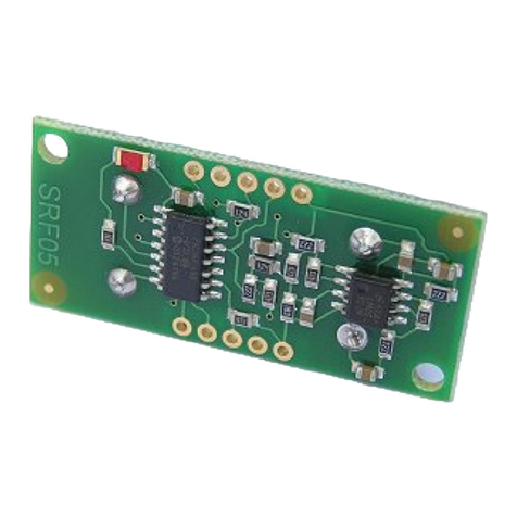
The figure below shows the PCB layout of the Speech Module:
Figure 1. Speech Module PCB Layout
Microphone
Record buttons
Record/Play Indicator
Control panel connector
Connection for output 3 & 4
Figure 2. Speech Module Installed on Control Panel PCB
Speech Module Installation
To install the Speech Module proceed as follows:
1) Ensure that all power is removed from the control panel before connecting the Speech
Module.
2) Plug the Speech Module (see Figure 2) onto the 8 way plug (SK1) of the control panel.
3) Connect the supplied lead to panel outputs 3&4 for messages 3&4.
4) Re-apply power to the system and proceed to the next section.
Recording Messages
The Speech Module can store four 12 second audio messages. Message 1 is allocated to channel
1 and message 2 is allocated to channel 2 etc. To record a message proceed as follows:
5) Press and hold the [RECORD] button, then press and hold either [REC1] for message 1 or
[REC2] for message 2 [REC3] for message 3 or [REC4] for message 4
6) Speak clearly into the microphone to record your message. During the recording process
the record indicator will illuminate.
7) To stop the recording process, release the record buttons. The recording process will
automatically end after 12 seconds and the record indicator will go out.
8) Repeat steps 1 to 3 for other messages, if required.
Programming the Control Panel
The control panel will then need to be programmed correctly in order for the Speech Module to
function as expected:
9) Select the “Engineer’s programming” menu.
10) Enter to select the “ARC No 1 Menu”. Within this menu program the following
options:
a) Enter to select the “Primary Telephone” number and then enter the first contact
telephone number of the person who is going to receive the message(s) followed by
/. *
b) Enter then to select the “Secondary Telephone” number and then enter
the second contact telephone number of the person who is going to receive the
message(s) followed by /. *
c) Enter to select the “Protocol Type” and then enter to select “Fast
Format/Speech Module”.
d) Enter to select the “Dial Attempts” and then enter the required number of dial
attempts (1-9).
e) Enter to select the “Fast Format Reporting Channels” and then use keys
,,,to select/deselect channels 1, 2, 3 & 4. Channels 1,2,3&4
correspond to messages 1,2,3&4. i.e., when channel 1 is triggered the panel will
report message 1 to the contact(s) telephone number. Channels 5 to 8 should be
deselected. Press /to accept the channel selection.
f) Enter to select the “Protocol Options” and then use keys to to
select/deselect options 1 to 8. Ensure that option 1 (Enable Speech Module) is
selected and options 2-8 are deselected. Press /to accept the selection.
g) Press to exit the “ARC No 1 Menu”.
*If both the primary and secondary numbers are programmed you can force the
control panel to dial the next number, even if the first attempt is acknowledged. In
order to do this you must program a + as the last digit of the telephone number. The
+ character is entered by pressing
then
.
11) Enter to select the “Fast Format Restore Channels” option and then use keys
to to select/deselect channels 1 to 8. If channels 1,2,3&4 are selected, the Speech
message will be reported both when the channel is activated and restored. For most
applications all channels will be deselected. Press /to accept the selection.
12) Enter to select the “Fast Format Open/Close Channels” option and then use keys
to to select/deselect channels 1 to 8. Channels 1-8 should be deselected. Press
/to accept the selection.
Programming Channels 1 & 2
1) Enter to select the “Fast Format/Speech Channels” type, then program the
following channels:
a) Enter to select channel 1. Enter output group, type and attributes (refer to
control panel installation manual). For example, to program channel 1 as
“Partition 1234 Fire Alarm”, enter 210 then press /to accept.
b) Enter to select channel 2. Enter output group, type and attributes (refer to
control panel installation manual). For example, to program channel 2 as
“Partition 1234 Burglar Alarm”, enter 202 then press /to accept.
c) Press to exit this menu.
2) Enter to select the “Communicator Options”, then use keys to to
select/deselect option 1 to 8. Ensure that option 1 (Enable Communicator) is selected. Press
/to accept the selection.
Programming Channels 3 & 4
Enter to select the “Panel Outputs” type, then program the following channels:
d) Enter to select channel 3. Enter output group, type, partitions and
attributes (refer to control panel installation manual). For example, to program
channel 3 as “Partition 1 Fire Alarm”, enter 210 then press /to
accept.
e) Enter to select channel 4. Enter output group, type, partitions and
attributes (refer to control panel installation manual). For example, to program
channel 4 as “Partition 1 Burglar Alarm”, enter 202 then press /to
accept.
Press to exit this menu.
Once these steps have been completed you can test the operation of the Speech Module.
Channels 3 & 4 are not to be used on a UL or CUL installation.
Testing the Speech Module
The procedure below shows how to perform a simple operational test for the Speech Module.
1) Select the “Engineer’s programming” menu.
2) Enter to select the “Send Test Call” option.
3) Press /to initiate a test call.
4) If you have a telephone on the same line as the control panel you can pick it up and listen
to the message.
5) During the test call you may press ,,orto switch between playing
messages 1 2 3 & 4.
6) The person listening to the message on their telephone can acknowledge the call by
pressing the [#] key. This will cause the panel to hang-up the call. If the call is
acknowledged using the [*] key the panel is put in remote control mode whereby it can be
controlled using a touch-tone telephone (see below).
7) Once the messages have been tested using menu 92, it is advisable to test the channels
respond correctly. For example, if you have programmed the function of channel 2 as
Burglar Alarm, then you should arm the system and activate an alarm zone, then verify that
the message is reported as expected.
Remote Control Commands
The figure below shows a quick guide to the remote control commands, for full details; refer to the
Touch-Tone Remote Control User Guide:
INS297-4

Specifications
Supply Voltage: 9 –16VDC
Current Consumption (Standby): 1mA
Current Consumption (Active): 7mA
Messages/Channels: 4
Message Length: 12 Seconds each
Dimensions: 52mm x 30mm x 10mm
Packed Weight: 25g
Product Identification (Barcode): PSM
Standards
The Speech Module conforms to European Union (EU) Low Voltage Directive (LVD)
73/23/EEC (amended by 93/68/EEC) and Electro-Magnetic Compatibility (EMC)
Directive 89/336/EEC (amended by 92/31/EEC and 93/68/EEC).
The CE mark indicates that this product complies with the European requirements for
safety, health, environment and customer protection.
This product is suitable for use in systems designed to comply with PD 6662: 2004
(prEN 50131-1: 2004) at Grade 2 and Environmental Class II.
Warranty
All Texecom products are designed for reliable, trouble-free operation. Quality is
carefully monitored by extensive computerised testing. As a result the Speech Module
is covered by a two-year warranty against defects in material or workmanship.
Texecom Ltd Limitations and Disclaimer
This system has been carefully designed to be as effective as possible, however not even the most advanced alarm
system can guarantee 100% protection. There are circumstances involving fire, burglary, or other types of emergencies
where it may not provide protection. Any security product whether commercial or residential may be compromised
deliberately or may fail to operate as expected for a variety of reasons. Texecom cannot accept liability for the System
failing to perform as expected. Some but not all of the reasons for this may include:-
Intruders may enter through an unprotected access point, circumvent a sensing device, evade detection by moving
through an area of insufficient coverage, disconnect a warning device, or interfere with or prevent the proper operation
of the system.
Intrusion detectors powered by AC will not operate if AC power is disconnected or inadequate. Any interruption to AC
power, however brief, will render that device inoperative while it does not have power. Power interruptions of any length
are often accompanied by voltage fluctuations which may damage electronic equipment such as a security system.
After a power interruption has occurred, immediately conduct a complete system test to ensure that the system
operates as intended.
A user may not be able to operate a panic or emergency switch possibly due to permanent or temporary physical
disability, inability to reach the device in time, or unfamiliarity with the correct operation.
Even if the system responds to the emergency as intended, the occupants may not have enough time to protect
themselves from the emergency situation. Where the alarm system is monitored, the authorities may not respond
appropriately or in time to protect the occupants or their belongings.
In the case of wireless detectors, signals may not reach the receiver under all circumstances which could include metal
objects placed on or near the radio path, deliberate jamming or other inadvertent radio signal interference.
Motion detectors can only detect motion within the designated areas as shown by the detection pattern in their
respective installation instructions. They cannot discriminate between intruders and intended occupants. PIR detectors
cannot detect motion which occurs behind walls, ceilings, floor, closed doors, glass partitions, glass doors or windows.
If the detector is battery operated, it is possible for the batteries to fail. Even if the batteries have not failed, they must
be charged, in good condition and installed correctly. Our wireless detectors have been designed to provide several
years of battery life under normal conditions. Ambient conditions such as high humidity, high or low temperatures, or
large temperature fluctuations may reduce the expected battery life. While each transmitting device has a low battery
monitor which identifies when the batteries need to be replaced, this monitor may fail to operate as expected. Regular
testing and maintenance will keep the system in good operating condition.
Passive infrared motion detectors operate by sensing changes in temperature. However their effectiveness can be
reduced when the ambient temperature rises near or above body temperature or if there are intentional or unintentional
sources of heat in or near the detection area. Some of these heat sources could be heaters, radiators, stoves,
barbeques, fireplaces, sunlight, steam vents, lighting and so on.
Dual technology microwave detectors must be adjusted by the installer so they do not detect motion outside the
intended protected area. The protection pattern may also be affected by metal objects or foil covered insulation.
Smoke detectors have played a key role in reducing residential fire deaths, however they may not activate or provide
early warning for a variety of reasons in as many as 35% of all fires, according to data published by the Federal
Emergency Management Agency. Some of the reasons smoke detectors used in conjunction with this System may not
work are as follows:-
Smoke detectors may have been improperly installed and positioned.
Smoke detectors may not sense fires that start where smoke cannot reach the detectors, such as in
chimneys, in walls, or roofs, or on the other side of closed doors.
Smoke detectors also may not sense a fire on another level of a residence or building. A second floor
detector, for example, may not sense a first floor or basement fire.
Finally, smoke detectors have sensing limitations. No smoke detector can sense every kind of fire
every time. In general, detectors may not always warn about fires caused by carelessness and safety
hazards like smoking in bed, violent explosions, escaping gas, improper storage of flammable
materials, overloaded electrical circuits, children playing with matches, or arson.
Depending on the nature of the fire and/or location of the smoke detectors, the detector, even if it operates as
anticipated, may not provide sufficient warning to allow all occupants to escape in time to prevent injury or death.
Alarm warning devices such as sirens, bells or horns may not alert people or wake up sleepers if they are located on
the other side of closed or partly open doors. If warning devices are located on a different level of the building from the
bedrooms, then they are less likely to wake or alert people inside the bedrooms. Even persons who are awake may not
hear the warning if the alarm is muffled by noise from a stereo, radio, air conditioner or other appliance, or by passing
traffic. Finally, alarm warning devices, however loud, may not warn hearing-impaired people.
Telephone lines or other types of communication medium needed to transmit alarm signals from protected premises to
a central monitoring station or other response service may be out of service. Telephone lines are also subject to
compromise by sophisticated intruders.
Any type of tampering whether intentional or unintentional may impair the proper operation of the system.
Although every effort has been made to make this module as reliable as possible. Even the most reliable electrical
devices, including this alarm system, may fail to perform correctly due to unexpected failure of a component part.
Inadequate maintenance is the most common cause of alarm failure. Therefore, test your system at least once per
week to be sure sensors, sirens,
and phone communications are all working correctly.
Although having an alarm system may make you eligible for reduced insurance premiums, regardless of its capabilities
however, the system is no substitute for insurance. Homeowners, renters or other occupiers should continue to insure
their lives and property.
Note to Installers
This warning contains vital information. As the only individual in contact with system users, it is your responsibility to
bring each item in this warning to the attention of the users of this system.
Texecom Limited, Bradwood Court, St. Crispin Way, Haslingden, Lancashire BB4 4PW, England.
Technical Support:
UK Customers Tel: 08456 300 600
(Calls charged at 3.36 pence per minute from a BT landline. Calls from other networks may vary.)
International Customers Tel: +44 1278 686197
Email: techsupport@texe.com
© Texecom Limited 2007
INS297-4
Other Texecom Control Unit manuals
Popular Control Unit manuals by other brands
Spirax Sarco
Spirax Sarco TD120 Installation and maintenance instructions

HYDAC FILTER SYSTEMS
HYDAC FILTER SYSTEMS CSM 1000 Series Installation and maintenance instructions
Exsys
Exsys EX-13072HM manual
ALZA
ALZA MS-105 user manual
GE HEALTHCARE
GE HEALTHCARE CU-960 instruction manual
Kemper
Kemper 145 2G Installation and operating instructions
