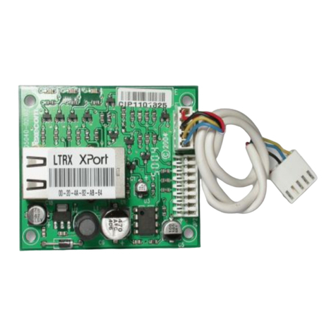
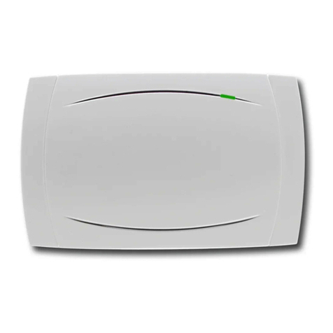
Texecom Premier Elite Com GSM User manual

Installation Manual
Premier Elite Com- GSM
INS315-5

INS315-5 2/21
Content
1.0 Introduction 4 ............................................................................................................................
1.1 SIM Card Types 6 ....................................................................................................................
1.2 Mounting the ComGSM 8 ........................................................................................................
1.3 Premier Elite ComGSM Layout 10 ...........................................................................................
1.4 Aerial Siting 11 .......................................................................................................................
1.5 Installation 13 .........................................................................................................................
2.0 Panel Configuration 15 .............................................................................................................
2.1 Premier & Premier Elite 24/48/88/168/640 15 ........................................................................
2.2 Using the SMS Control Commands 15 ....................................................................................
2.3 What will be sent in the Text Message 18 ..............................................................................
2.4 Premier 48/88/168/640 & Premier Elite 24/48/88/168/640 18 ................................................
2.5 Premier 412/816/816 Plus/832 19 ..........................................................................................
2.6 Specifications 20 ....................................................................................................................
2.7 Standards 20 ..........................................................................................................................
2.8 Warranty 21 ...........................................................................................................................

INS315-5 3/21

INS315-5 4/21
1.0 Introduction
The Premier Elite Com GSM is a 2G module that can be connected to any
Premier or Premier Elite control panel; however functionality differs depending
on the type of Premier panel installed and the type of SIM card that is used. The
tables below show which features are available and the type of SIM card required
to enable the services.
N A secondary form of communications should be used as back up where possible.
N When using Alarm reporting over IP with Montex, SIA, Contact ID or, Fast Format
may be used, however if using Texbase SIA is NOT supported. Some receivers may
require a Fixed IP address, please check with your provider.

INS315-5 5/21
N The Com port type must be programmed as one or the other, it is not possible
to use both GSM and GPRS (IP Only) functionality at the same time.

INS315-5 6/21
1.1 SIM Card Types
SIM cards are split into two types:
Dynamic IP SIM cards – the ‘everyday’ kind of SIM card used in mobile
phones. GSM units that use this kind of SIM card can access any data on the
internet but cannot be contacted from the internet. This type of SIM card
should be used for SMS text messaging & Upload/Download via GSM. A data
number will be required to uses Upload/Download.
Fixed IP SIM cards – specialist SIM cards that have a fixed, internet public IP
address which means that in addition to being able to access any data on the
internet they can be contacted from the internet. For Premier Elite
ComGSM this means they can be used for both alarm reporting and
upload/download via IP (GPRS) If a data number is also available, it is possible
to use upload/download via the data number (GSM) instead of the IP address.
SIM cards can have two different phone numbers:
Voice Number: used for voice calls and SMS
Data Number: used for GSM data calls (Upload/Download)
Either of these facilities can be enabled/disabled by the operator.
NCare should be taken when using Pay as you go SIM cards, make sure you have
the ability to Top Up. Pay as You Go SIM cards generally DO NOT have data
numbers, please check with your service provider.
SIM cards purchase
Texecom DO NOT supply SIM cards. These will need to be sourced locally, and
care should be taken to source SIM cards in the country where the unit is to be
used. This will help reduce costs and avoid excessive data charges. When using
GSM as the communication method, Data services will need to be enabled for
upload/download, this may or may not be the same Telephone number.
GPRS SIM card setup
In order to use GPRS, the Premier Elite ComGSM must be programmed with

INS315-5 7/21
certain parameters which are dictated by the SIM card used. This is no different
from mobile phones (often called the ‘GPRS Setup’) except that mobile phones are
often supplied pre-configured.
The configuration consists of the following:
APN (Access Point Name)
Username
Password
These parameters are entered into the Premier Elite ComGSM using a Texecom
PC program called ‘APNProgrammer’ (on the Texecom CD supplied with the panel)
with the Premier Elite ComGSM powered and connected to a PC via a Texecom
USBCom.
To power the Premier Elite ComGSM whilst programming connect the supplied
harness to the control panel com port, and the other end to the Engineers Keypad
port on the Premier Elite ComGSM. The Texecom USBCom should be
connected to the com port on the Premier Elite ComGSM.
Use APNProgrammer to upload the required information to the Premier Elite
ComGSM.
The supplier of the SIM card should provide the information required.

INS315-5 8/21
1.2 Mounting the ComGSM
Remove the screw cover by locating the two small indents on the upper and lower
edge with a smalln screwdriver. Exoessive force in not required.
Remove the retaining screw
If removal from mounting tamper detection required, the housing MUST be fixed at

INS315-5 9/21
this point.

INS315-5 10/21
1.3 Premier Elite ComGSM Layout
Antenna connection1.
Com1 data connection to Premier control panel2.
Tamper switch (Lid and off the wall tamper when fixed correctly)3.
Engineer keypad connector (only used to power the Premier Elite ComGSM4.
when using APNProgrammer)
Status LED’s (see table below)5.
Tamper Switch connector6.
Power LED (Green)7.
Tamper switch (not used in this housing)8.
Option switches (see table below)9.
SIM Socket10.
Audio connector (connect when the ComGSM is used as a backup for11.
COM300/COM2400)
TX LED (Red flashes when communicating)12.

INS315-5 11/21
Option Switches
The option switches [8] function as follows:
Status LEDs
The four status LED’s [5] indicate the following:
NThe signal strength LED works for both GSM and GPRS modes; however the dBm
reading is only seen on the keypad in GSM mode.
1.4 Aerial Siting
ALWAYS do a site survey to find an area
of strong signal before installation.
Installing a Com GSM with a weak signal
is bad installation practice.
The aerial should be mounted vertically
(see below) at the point of strongest
signal. This is usually the highest point
in the building (often the loft area).
The aerial must be installed
internally

INS315-5 12/21
Avoid installing the aerial directly under
metal roofs or within metal skinned
buildings because this will reduce the
signal strength and may inhibit
operation completely. If this is
unavoidable, the strongest signal will be
found away from the metal roof or close
to large external windows or skylights.
Avoid installing the aerial close (2
metres) to cable runs, ducting,
structural metalwork, metal pipes,
water tanks and electronic equipment,
e.g. photocopiers, fax machines etc.
These can have similar effects to metal
roofs.
Reliable operation is unlikely with a low
signal strength. If the display shows
that the signal strength is 40%
(-88dBm) or lower,
you should improve the signal strength.
This may be achieved by repositioning
the aerial. The GPRS aerial lead should
not be cut, therefore repositioning the
aerial may require that the Premier
Elite Com GSM is also repositioned.
The aeriel lead may be extended by a
maximum of 10 Mtrs.
The DualCom® CS2366 Radio Test Set
is ideal for surveying a site. This
handheld unit can check the availability,
signal strength and interference status
of all surrounding Base Stations. In
addition, it will identify the best location
for a GPRS aerial within the building,
help to avoid sources of interference
and can confirm the availability of a
GPRS service at the proposed site.
Where a Nokia ‘Net Mon’ phone is
available and a Vodafone SIM Card is
fitted, it may be used in the same
manner as the CS2366 Radio Test Set.
Alternatively, a Vodafone mobile phone
may be used to locate the point of
strongest signal. The signal strength
indicator is normally a bar or line at the
side of the display on the mobile
telephone. Note: The mobile phone
MUST use the Vodafone network. A
mobile phone that uses a different radio
network will NOT show the correct
signal strength.
This ‘mobile phone’ method cannot
provide information on the availability,
signal strength and interference status
of all radio Base Stations in the
surrounding area. Use of the CS2366
Radio Test Set is recommended.

INS315-5 13/21
When you have identified the point of
the strongest signal, make a note of this
point and use it when installing the
Premier Elite Com GSM aerial.
Remember: It is always easier to find
the point of strongest signal before the
equipment is fitted to a wall. Moving
aerials, cables, trunking etc. after
installation is wasted time and effort.
1.5 Installation
The Premier Elite Com GSM module should be installed as close to the control
panel as possible, so that the harness lead supplied with the unit is able to plug
onto the control panel communication port.
N The connection harness cannot be extended
1. Route the harness lead into the module housing using the cable entry plate at
the top of the unit, and plug the connector onto COM1 [2]
2. Install the module in the required location using suitable fixings.
3. Route the other end of the harness lead into the control panel housing. DO NOT
CONNECT at this point.
4. Connect the GSM antenna to the antenna connector on the module [1] and site
the antenna as high as possible.
5. Unlock the SIM socket by sliding the locking tab downwards. Insert the SIM card
into the holder with the chamfered corner to the top left. Push the holder back into
position and lock the SIM by sliding the locking tab upwards.
NThe SIM card must be inserted before connecting the Premier Elite ComGSM
module to the control panel, and must not be removed until after the power supply
to the Premier Elite ComGSM module has been deactivated.
6. Set the option switches as required, see page 6.
7. Now connect the harness lead onto the control panel communication port (COM
2 for the Premier 24; COM 1 or 2 for the Premier 48/88/168/640 Premier Elite

INS315-5 14/21
24/48/88/168/640& Premier 412/816/816Plus/832).
The module should now be powered and the heartbeat LED [5] should be flashing.
NYou should check and confirm that the signal strength is still the same as
recorded during the site survey.

INS315-5 15/21
2.0 Panel Configuration
2.1 Premier & Premier Elite 24/48/88/168/640
Text Messaging and Upload Download via GSM
GSM Mode (panel port programmed as GSM Module, Dynamic IP SIM card)
Enter “Engineers Programming” mode and select “UDL/Digi Options”, then1.
select “Com Port Setup”. Ensure Com Port is programmed as “GSM Module”.
Now select the “Digi Options” menu and make sure that “Digi Option 1” is
programmed for “Digi is Enabled”.
Now select “Program Digi” and ensure the following options are programmed for
one of the ARC options:
Protocol: “SMS Messaging”.
Primary No: The number of the recipient’s mobile telephone.
Secondary No: Secondary mobile telephone number (if required).
Account No: Leave blank.
Dialling Attempts: Program as required.
Report Areas: Program as required.
Reports: Program as required.
Config.: Program as required.
Protocol Options : Program as required.
UDL Options : Change rings before answer to 1 if using GSM
Upload/Download.
All three status LED’s should now be on,(it can take up to 1 minute for the LED's to
become stable.) if status LED 3 is off or flashing, this indicates a low GSM signal
level. If the signal level is low, try moving the antenna to improve the reception.
2.2 Using the SMS Control Commands
Control commands can be sent to the Premier Elite ComGSM module to allow
remote control and interrogation of the alarm system.

INS315-5 16/21
Select the send text message option on your mobile telephone.1.
Enter the telephone number of the Premier Elite ComGSM module.2.
Enter the text command, see SMS Control Commands.3.
Select send on your mobile telephone.4.
When using the SMS Control Commands shown in the tables below the following
should be noted:
???? = User code, this must proceed all commands.
[areas] = Areas 1 to 8 or A to P. If the areas are not specified then all areas will be
selected.
[s] = Send back status report
(zones) = List of zones, each zone must separated by a space e.g. 1 12 167 etc.
(outputs) = List of outputs, e.g. 1234 etc.
(message) = A maximum of 32 characters.

INS315-5 17/21

INS315-5 18/21
2.3 What will be sent in the Text Message
The following information will be received in the text message:
2.4 Premier 48/88/168/640 & Premier Elite
24/48/88/168/640
Alarm Reporting & Upload/Download via IP
IP Mode (panel port programmed as ComIP, fixed IP SIM card)
1. Enter "Engineers Programming" mode and select "UDL/Digi Options", then
select "Com Port Setup". Ensure Com Port is programmed as "ComIP". Leave the IP
address, port & gateway blank.
2. Now select the "Digi Options" menu and make sure that "Digi Option 1" is
programmed for "Digi is Enabled".
3. Now select "Program Digi" and ensure the following options are programmed for
one of the ARC options:
a) Protocol:Program as required.
b) Account No: Program as required
c) Dialling Attempts: Program as required.
d) Report Areas: Program as required.

INS315-5 19/21
e) Reports: Program as required.
f) Config.: Program as required.
g) Protocol Options : Connect Via IP should be enabled..
h) For Upload/Download via Wintex edit the Account/Panel Details and fill in the IP
address you have been given and Port number.
All three status LED’s should now be on, if status LED 3 is off or flashing, this
indicates a low GSM signal level. If the signal level is low, try moving the antenna
to improve the reception.
2.5 Premier 412/816/816 Plus/832
Alarm Reporting and Upload/Download via IP
IP Mode (panel port programmed as Com IP, fixed IP SIM card)
1. Enter "Engineers Programming" mode and select "Communicator Options", then
select "Download Options 76". Ensure Com Port Option 5 is programmed as
"ComIP" option 3.
2. Leave the following blank Local IP address, Local IP Port & Gateway
3. Now select the "Communicator Options" menu and "Enable Communicator"
4. Now select "ARC’s" and ensure the following options are programmed for one of
the ARC options:
a) Protocol : Program as required.
b) Report for : Program as required
c) Account Numbers : Program as required.
d) Reporting Options : Program as required.
e) Protocol Options : Connect Via IP should be enabled.

INS315-5 20/21
f) For Upload/Download via Wintex edit the Account/Panel Details and fill in the IP
address and Port number you have been given.
All three status LED’s should now be on, if status LED 3 is off or flashing, this
indicates a low GSM signal level. If the signal level is low, try moving the antenna
to improve the reception.
2.6 Specifications
Electrical
Supply: 9 to 14VDC
Current Consumption: 35mA quiescent; 100mA when active
Environmental
Operating Temperature: -10°C to +55°C
Maximum Humidity: 95% non-condensing
Physical
Dimensions: 145mm x 90mm x 30mm
Packed Weight: 200g (approx.)
2.7 Standards
2004/108/EC (CE directive): Hereby,
Texecom declares that this device is in
compliance with the essential
requirements and other
relevant provisions of Directive
2004/108/EC.
Weee Directive: 2002/96/EC (WEEE
directive): Products marked with this
Table of contents
Other Texecom Control Unit manuals
Popular Control Unit manuals by other brands
Resol
Resol HKM2 manual

Warren rupp
Warren rupp Sandpiper SA1 Service & operating manual
Maxsys
Maxsys PC4204 installation instructions

Coherent Solutions
Coherent Solutions BERTPXIe-1003 user manual

Siemens
Siemens AE-30U Operation and installation instructions

Watts
Watts AMES 950GD-15 Installation, operation and maintenance
