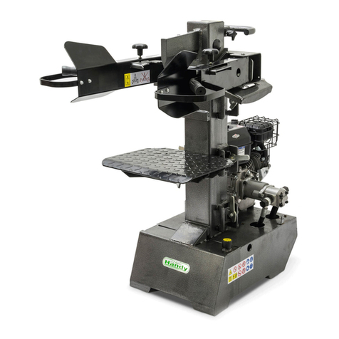
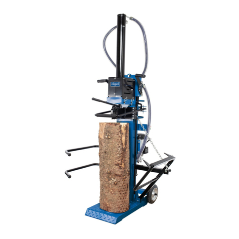
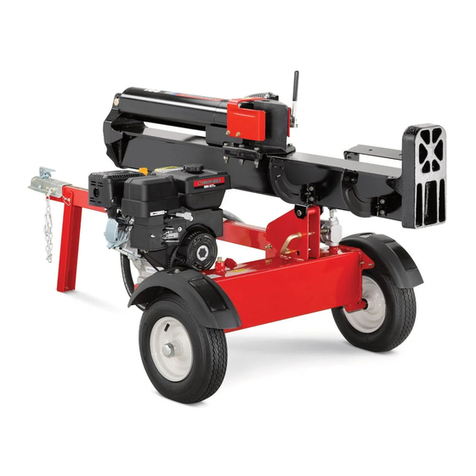
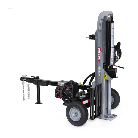
The Handy THPLS7TE Installation and maintenance instructions

Page 1
OPERATOR’S MANUAL AND PARTS LIST
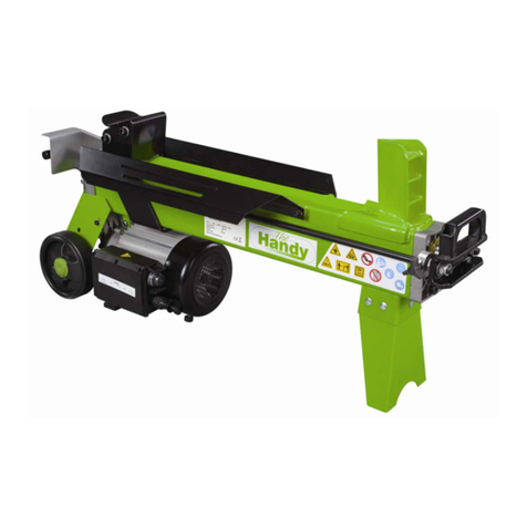
ELECTRIC LOG SPLITTER - THPLS7TE
Spares & Support 01793 333212
www.thehandy.co.uk
Before use please read & understand this manual, paying particular
attention to the safety instructions.
2010 v1

Page 2
SAFETY INSTRUCTIONS 3
MAJOR PARTS 4
SPECIFICATIONS 5
ASSEMBLY 6-7
OPERATION 8-9
PARTS DIAGRAM AND LIST 10-11
EC DECLARATION OF CONFORMITY 12
CONTENTS

Page 3
SAFETY INSTRUCTIONS
Read and understand the owner’s manual and the labels
affixed to the logsplitter. Learn its application and limitations
as well
instructions for future reference.
x Use sturdy footwear and a helmet with eye and ear protection.
Protect exposed parts of your body. Wear heavy duty gloves,
preferably made of leather.
x Do not wear loose clothing or jewellery. Keep hair, clothing and
gloves away from moving parts.
x Do not operate the logsplitter if you are tired, ill or under the
x Do not smoke when using the logsplitter.
x Ensure that bystanders, children and pets stay at a safe
distance of at least 15m.
x Do not operate the machine on a steep slope or slippery ground.
x Inspect the machine and all attachments before use for any worn or
damaged parts. Do not use until the parts are repaired or replaced.
x Before starting the motor make sure you have a clear work area
and secure footing.
x Ensure that any extension lead used is no longer than 10 metres
and its cross section is no less than 2.5mm2
current to the motor.
x The logsplitter should not be exposed to direct sunlight, high
temperatures or damp and wet conditions. In addition, do not use
x Ensure that the motor is switched off and the machine is
unplugged before transporting or carrying out any maintenance.
• Clean the logsplitter after each use and follow the instructions for
lubricating.
• Dispose of any unwanted oil at your local recycling centre.

Page 4
MAJOR PARTS
1 Transport Handle 2 Ram Travel Adjusting Rod
3 Split Wedge 4 Ram
5 Plug and Switch 6 Control Levers Connection Bracket
7 Top Motor Shield 8 Motor
9 Side Bracket, SuppRrt Table 10 Table Lock Down Hook
11 Base Cover 12 Wheels
13 Base 14 Oil Tank Cover/Air Bleeder
15 Front Bracket, Support Table 16 Control Lever Guard
17 Adjustable Log Holder 18 Log Holder Adjusting Knob

Page 5
SPECIFICATIONS
Model No. THPLS7TE
Motor 230V~50Hz 3000W IP54
Log Size Capacity Diameter = 12-32cm
Length = 104/78/52cm
Maximum Force 7 ton
Hydraulic Pressure 22 Mpa
Hydraulic Oil Capacity 5 litres
Ram Travel 480mm
Forward Speed 3.9cm/sec
Retract Speed 14.5cm/sec
Noise Pressure Level 80.1 dB(A) under no load
92.5 dB(A) under full load
Overall Sizes Length = 83cm
Width = 46cm
Height = 147cm
Weight 115kg
Electrical Requirements:
The log splitter should be connected to a standard 230V ±10%/50Hz ±1Hz electrical supply
which has protection devices of under-voltage, over-voltage, over-current as well as residual
current device (RCD) with maximum residual current rated at 0.03A. Electrical connection
rubber cables must comply with EN60245 which are always marked with symbol H 07 RN.

Page 6
ASSEMBLY
At least two people are required to unpack the log splitter package because of its weight.
Following the diagrams above, carefully unpack the log splitter, using B and C to support
package A.
You should have the following contents:
Log Splitter Frame,Control Lever and Guard Assembly,Removable Support Table,Owner’s
Manual.
A
B
C

Page 7
• Pull Spring Pin (A) to remove Lock Pin (B).
• Apply a thin coat of grease to both surfaces of the Control
Lever Guard as shown.
• Insert Control Lever and Guard Assembly and ensure that
Bracket (C)
• Lock the Control Lever and Guard Assembly down with
the Lock Pin (B) and Spring Pin (A).
• Repeat on the other side.
• Three positions are available for the Support Table for
different splitting lengths.
•
frame.
• Insert the Support Table in the required brackets (E).
• Turn the Lock Down Hooks (D) 90 degrees to secure
the table.
to bleed the air out of the hydraulic system
The cover of the oil tank should be loosened until air can
move in
tank filler should be detectable during operation.
Failure to do this will keep the sealed air compressed in
the hydraulic system and continuous air compression
and decompression will blow the seals of the hydraulic
system and cause permanent damage.
Before moving the log splitter, make sure the oil tank cap is
tightened to avoid any leakage. There are two wheels to
facilitate moving. If using a crane to move the machine, lay
the hoist around the housing, never the handle.
ASSEMBLY, cont’d
A
B
C
Grease
D
E
A

Page 8
OPERATION
Work safely and save effort by planning your work beforehand.
Position your logs so that they can be easily lifted onto the log
splitter and, either stack close by or load onto a truck/trolley as
soon as they are split.
Inspect your logs and do not attempt to split logs containing
nails, wire or debris which could damage the log splitter.
The splitter can accommodate logs up to 104cm in length.
When cutting up limbs or large sections do not cut longer than
100cm. Place the support table into the position nearest to the
log length - 52cm, 78cm or 104cm, and secure.
Before operation, apply a thin coat of grease to the surfaces
of the ram.
• Loosen the oil tank cover a few turns to allow air to move
freely as described above. Re-tighten when you have
• Plug in the power cord, ensuring that it does not get in the
way of the operating mechanism, and keep it out of the way
of the operator’s feet.
• Start the motor - the wedge ram should rise to the highest
position automatically.
• If operating in low temperatures, allow the engine to run for
15 minutes to preheat the oil.
• Check the operation of both control levers by lowering them
so that the splitting ram lowers to approx 5cm above the
highest table position. Release either lever and the splitting
wedge will stay in the same position. Release both levers
at the same time and the splitting wedge will return to the
highest position.
To set the wedge ram stroke:
• Move the splitting wedge to the desired position. The
upper position of the ram wedge travel should be about
3-5cm over the logs to be split.
• Turn off the engine.
• Release the Handscrew (A). Raise the Adjusting Rod (B)
until resistance is felt from the spring inside.Tighten the
Handscrew.
• Release both control levers and start the engine.
• Check the upper position of the splitting wedge.
52cm
78cm
104cm
Grease

Page 9
OPERATION, cont’d
To operate:
• Place a log on the
Do not attempt to split a log at an angle and do not place
the log across the splitter - always split in the direction of
the grain.
• Adjust the Log Holders (A) to suit the diameter of the log.
• Hold the log closely with the clamping brackets in the
control lever guards.
• Lower levers to start splitting.
• Releasing either of the levers stops the motion. Releasing
both levers returns the splitting wedge to the upper
position.
Hints and Tips:
• Never attempt to load the log splitter whilst the ram is in
motion.
• Never try to split two logs at once.
• Keep your hands away from the splits and cracks which
appear whilethe log is being split.
• Do not remove jammed logs with your hands - stop the
engine and loosen the log with a downward strike on the
log with a hammer.
• Do not force the tool and do not make alterations to the
log splitter as this could be dangerous and invalidate your
warranty.
• Do not try to split logs larger than recommended in the
• After long periods of operation the splitting wedge may
• Check the level of the hydraulic oil regularly using the
dipstick. In addition the oil should be changed once a
year.
Recommended oils are:
SHELL Tellus 22
MOBIL DTE 11
ARAL Vitam GF22
BP Energol HLP-HM 22

Page 10
PARTS DIAGRAM
Wiring Diagrams

Page 11
PARTS LIST
No Part No Description Qty No Part No Description Qty
1 TH106-1 Work Table 1 40 TH106-40 Pump Intake Nozzle 1
2 TH106-2 Round Cover 2 41 TH106-41 Oil Pump 1
3 TH106-3 Operating Handle 2 42 TH106-42 Spring Washer M86
4 TH106-4 Lever Handle 2 43 TH106-43 Inner Hexangular Screw
M8x35
4
5 TH106-5 Right Guard Assembly 1 44 TH106-44 High Pressure Oil Hose 3 1
6 TH106-6 Knob 2 45 TH106-45 Valve Tube Nozzle 2
7 TH106-7 Clamping Fork (Right) 2 46 TH106-46 Valve Injection Nozzle 1
8 TH106-8 Left Guard Assembly 2 47 TH106-47 Oil Return Pipe 1
9 TH106-9 Control Lever Shaft 2 48 TH106-48 CA Valve 1
10 TH106-10 Thin Nut 2 49 TH106-49 Washer M20 6
11 TH106-11 Washer M810 50 TH106-50 Valve Plug 1
12 TH106-12 Hex Bolt 2 51 TH106-51 T-Connector, Tape 1
13 TH106-13 Control Link Plate 1 52 TH106-52 High Pressure Oil Hose 1
14 TH106-14 Fork 2 53 TH106-53 High Pressure Oil Hose 1
15 TH106-15 Locknut M8 4 54 TH106-54 T-Plug, Nut 1
16 TH106-16 Clamping Fork (Left) 1 55 TH106-55 Bolt M8x25 2
17 TH106-17 Hand Screw 156TH106-56 Draw Sleeve 1
18 TH106-18 Square Cover 1 57 TH106-57 Pump Guard 1
19 TH106-19 Nut 1 58 TH106-58 Wheel 2
20 TH106-20 Draw Rod 1 59 TH106-59 Circlip M16 2
21 TH106-21 Pin 1 60 TH106-60 Screw M6x16 4
22 TH106-22 Circlip 4 61 TH106-61 Locknut M10 10
23 TH106-23 Plastic Insert 1 62 TH106-62 Cap 1
24 TH106-24 Plastic Insert 1 63 TH106-63 Lock-Out Lever 6
25 TH106-25 Inner Hexangular Screw
M6x16
2 64 TH106-64 O Ring M32x3.55 1
26 TH106-26 Locknut M4 2 65 TH106-65 Bolt M10x35 6
27 TH106-27 Plastic Insert 1 66 TH106-66 Wheel Cover 2
28 TH106-28 Plastic Insert 1 67 TH106-67 Bolt M16x25 1
29 TH106-29 Inner Hexangular Screw
M6x10
2 68 TH106-68 Washer M16 1
30 TH106-30 Stop Limit Plate 2 69 TH106-69 Upright Tube Weldment 1
31 TH106-31 Thin Nut M16 1 70 TH106-70 Lock Shaft 1
32 TH106-32 Switch 1 71 TH106-71 Cylinder 1
33 TH106-33 Screw M4x6 2 72 TH106-72 Sliding Plate 4
34 TH106-34 Motor 1 73 TH106-73 Wedge Bracket Weldment 1
35 TH106-35 Washer M10 3274 TH106-74 Bolt M6x30 1
36 TH106-36 Bolt M10x30 4 75 TH106-75 Screw M6x20 4
37 TH106-37 Junction Box 1 76 TH106-76 Armguard Plate 1
38 TH106-38 Hose Clamp 4 77 TH106-77 Washer M62
39 TH106-39 Intake Hose 1 78 TH106-78 Locknut 2

16
EC DECLARATION OF CONFORMITY
Declaration of conformity
Pursuant to the regulations of the following EC Directives:
- Machinery Directive: 2006/42/EC
- Low Voltage Directive: 2006/95/EC
- EMC Directive: 2004/108/EC
Handy Distribution Ltd hereby declares that the product:
Machine type: 7T Log Splitter
Machine model: THPLS7TE
Mass in kg: 115kg
Rated Power: 3000W S6(40%)
Max. Force: 7T
Max. log capacity.: 1040/780/520mm
Conforms to the main safety requirements of the EC Directives listed above.
This conformity is based on the following standards and normative documents:
2006/42/EC- Annex I/05.06
- EN60204-1:2006
- EN609-1:1999+A2
- EN55014-1:2006
- EN55014-2:1997+A1
- EN61000-3-2:2006
- EN61000-3-11:2000
The responsible person, based within the EC, is identified below:
Name: Mr. Simon Belcher
Title: Managing Director
Company: Handy Distribution Ltd.
Address: Hobley Drive, Stratton St Margaret, Swindon, Wiltshire, SN3 4NS.
Signature : Date: 7th Jan, 2010

To order spare parts and see the complete range of garden
machinery and garden equipment from Handy, visit:
www.thehandy.co.uk
Spares & Support: 01793 333212
Other manuals for THPLS7TE
1
Table of contents
Other The Handy Log Splitter manuals
The Handy
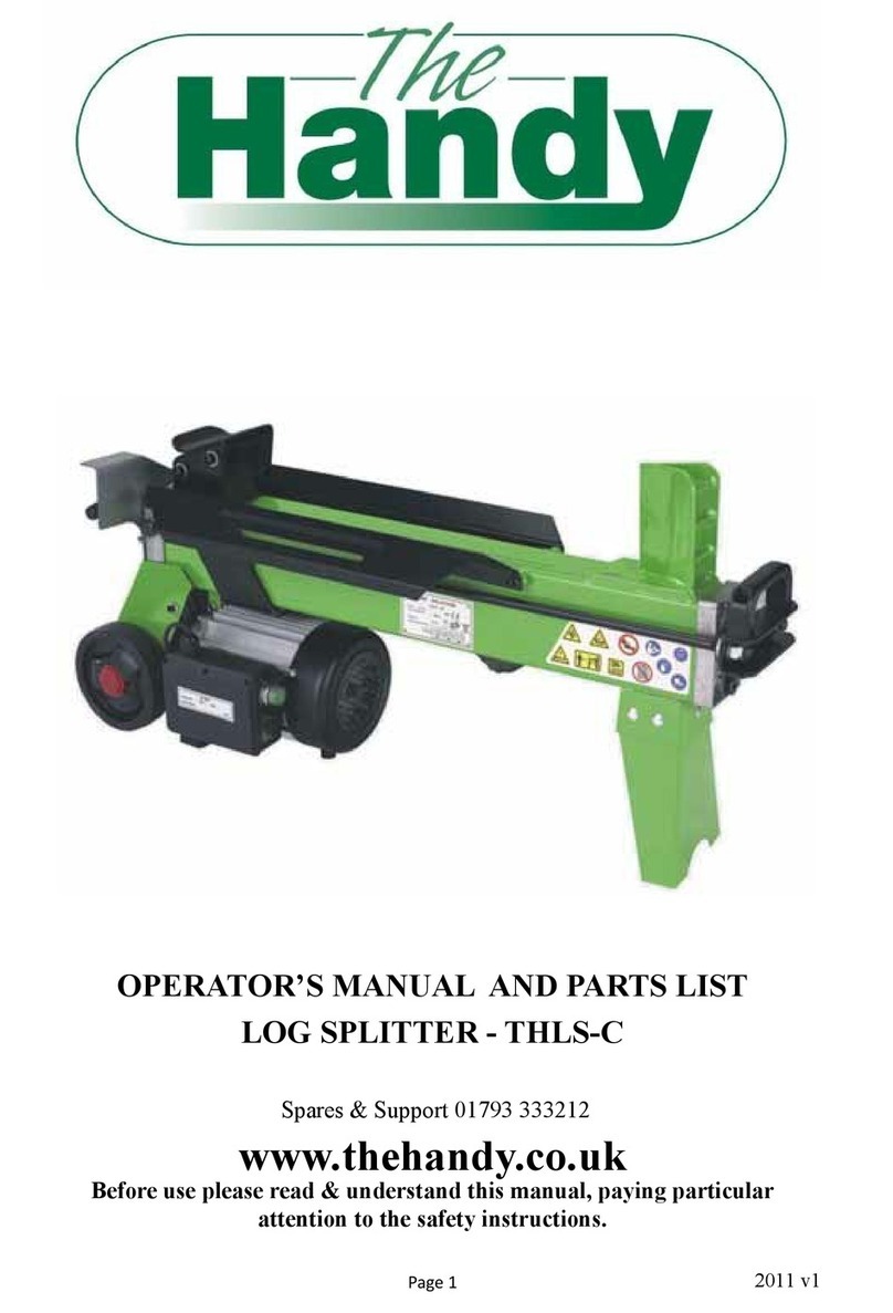
The Handy THLS-C Installation and maintenance instructions

The Handy
The Handy THLS-6 User manual
The Handy
The Handy THLSS-B User manual
The Handy
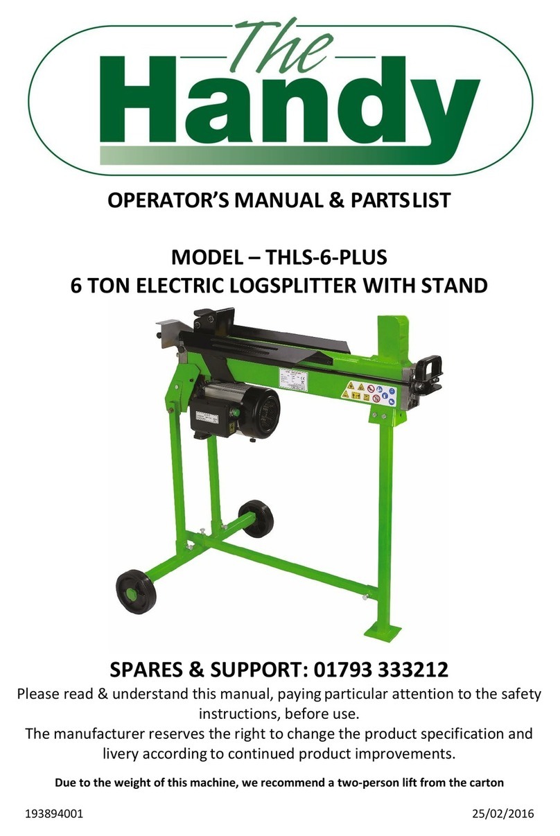
The Handy THLS-6-PLUS User manual

The Handy
The Handy THLS-6G User manual
The Handy
The Handy THLSV6 User manual
The Handy
The Handy THLS-4 Installation and maintenance instructions

The Handy
The Handy THLSS-B Installation and maintenance instructions

The Handy
The Handy THMLS Installation and maintenance instructions

The Handy
The Handy THLS-4 User manual
