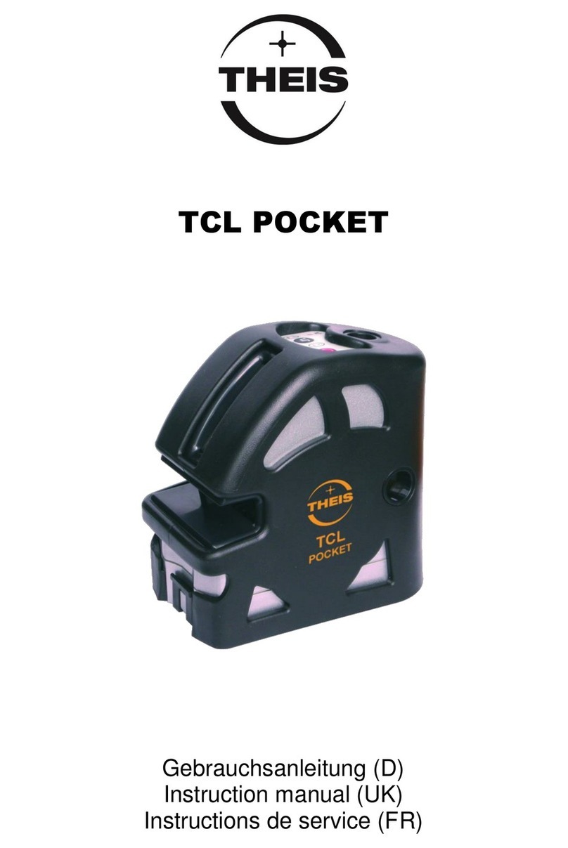
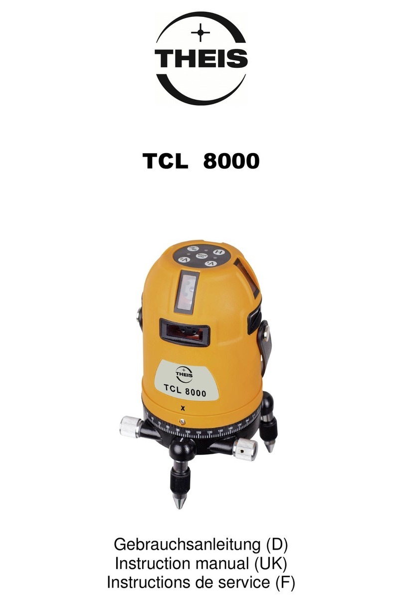
THEIS TCL 80 User manual

Gebrauchsanleitung (D)
Instruction manual (UK)
Instructions de service (F)
TCL - 80
Gebrauchsanleitung D
Vorwort
Der THEIS TCL-80 ist ein vollautomatischer, motorisch selbstnivellierender
Kreuzlinienlaser. Der Laser sendet bis zu 4 vertikale und 4 horizontale Laserlinien
mit sehr guter Sichtbarkeit aus. Die Vertikallinien stehen in einem Winkel von 90°
zueinander (x, y)
Ausgehend vom Kreuzungspunkt der Laserlinien wird zusätzlich ein Laserpunkt
auf den Boden projiziert und somit die Aufstellung des Gerätes wesentlich
vereinfacht.
Sowohl die mitgelieferte Laserbrille, als auch die Zieltafel verbessern die
Sichtbarkeit der Laserlinien.
Der Empfänger TEK (Option) wird bei Arbeiten in größerer Entfern
ung oder bei zu
großer Umgebungshelligkeit eingesetzt.
Alle Instrumente werden vor Auslieferung sorgfältig geprüft.
Damit Sie stets ein einsatzbereites Gerät haben, sollten folgende Hinweise
beachtet werden:
1. Das Gerät niemals nass im Behälter aufbewahren.
2. Genauigkeit vor jedem Einsatz überprüfen, da wir keine Haftung für
Dejustierung übernehmen können.
3. Hinweise zur Behandlung der Akkus beachten.
4. Laser-Austrittfenster des TCL-80 und Sensorfenster des Empfängers
(Option)
schonend behandeln.
1. Bedienungselemente / Anzeige
(1) Laseraustritt Vertikallinie X (4x)
(2) Laseraustritt Horizontallinie (4x)
(3) Fußschraube
(4) Laseraustritt Lotpunkt
(5) Seitenfeintrieb 360°
(6) Fuß
(7) Akkufach rückseitig
(8) Tastatur
(9) Ladegerät/ Ladebox
1 2
1
2
3
6
8
5
4
7
9

Tastatur
(10) Taste Vertikallinie (V1)
(11) Taste Outdoorbetrieb
(12) Anzeige Outdoorbetrieb Ein
(13) Taste Horizontallinie (H)
(14) Ein/ Aus-Schalter
(15) Betriebsanzeige / Batteriekontrollleuchte
(16) Taste Vertikallinie (V2)
2. Aufstellen
TCL-80 auf einen stabilen, flachen Untergrund aufstellen oder auf ein Stativ fest
aufschrauben. Zuvor den Stativkopf möglichst waagerecht ausrichten, da die
Nivellierautomatik des Kreuzlinienlaser max. einen Winkel von +/-4°ausgleichen
kann. Ohne Stativ kann das Gerät ggf. mit Hilfe der Fußschrauben (3) grob
ausgerichtet werden.
3. Bedienung
Gerät einschalten. Betriebsanzeige (15) leuchtet rot und 2 Horizontallinien
leuchten.
2 weitere Horizontallinien aktivieren.
2 Vertikallinien in Y- Richtung und den Lotpunkt aktivieren.
2 weitere Vertikallinien in X- Richtung aktivieren.
Durch Drücken der verschiedenen Tasten für Horizontal- bzw. Vertikallinien
können die Laserlinien auch wieder ausgeschaltet werden.
Der Kreuzlinienlaser ist um 360°drehbar, so dass d ie Laserlinien auf die
gewünschten Ziele ausgerichtet werden können. Mit dem Feinstellknopf (5) des
360°Seitenfeintriebes ist eine präzise Einstellung der Laserlinien möglich.
Falls der Arbeitsbereich der automatischen Nivellierung überschritten wird, werden
alle Laserlinien sofort ausgeschaltet. Somit werden Fehlmessungen vermieden.
Bei Arbeiten im Außenbereich, in größerer Entfernung und bei schlechter
Sichtbarkeit der Laserlinien wird der Empfänger TEK (Option) eingesetzt.
Die Taste Outdoorbetrieb (11) muss bei Verwendung des Empfängers TEK
gedrückt werden. Die LED (12) zeigt die Aktivierung des Outdoorbetriebes an.
Nach Beendigung der Vermessungsarbeiten Gerät mit Taste (14) ausschalten.
3 4
4. Stromversorgung
4.1 TCL - 80
Wenn die Batteriekontrollleuchte (15) blinkt, müssen die Akkus geladen werden.
Dazu Deckel des Akkufachs (7) öffnen, Akkus entnehmen und in die Ladebox
zum Laden einlegen. Auf richtige Polung achten! Wenn die Akkus fertig geladen
sind, leuchtet eine grüne LED an der Ladebox. Anschließend Akkus wieder in
Akkufach des Lasers einlegen. Dabei auf richtige Polung achten (siehe Hinweis
im Batteriefach). Es können auch normale Alkaline Batterien verwendet.
Die alten Alkaline Batterien sachgemäß entsorgen und gegen neue Batterien
(Größe AA) ersetzen. Anschließend Batteriedeckel wieder einsetzen.
4.2 Empfänger TEK
Wenn die LED (22) blinkt, sollte die Batterie (9 V, E-
Block) gewechselt werden, da
sonst die Reichweite eingeschränkt sein kann.
Schraube (24) des Batteriedeckels aufschrauben und Deckel abnehmen.
Alte Batterie sachgemäß entsorgen und bei neuer Batterie auf richtige Polung
achten (siehe Symbol im Batteriefach). Anschließend Batteriedeckel wieder
einsetzen.
5. Empfänger TEK
Empfänger durch Drücken der Taste (23) einschalten. Die Betriebsanzeige (22)
zeigt den eingeschalteten Zustand an.
Mit der Taste Mode (30) die Fein- oder Grobeinstellung wählen (Grundeinstellung
ist Fein). Im Feinbereich leuchtet die LED (28). Im Grobbereich ist die LED aus.
Das akustische Signal kann mit der Taste (29) ausgeschaltet oder aktiviert
werden (Grundeinstellung ist Horn Ein).
Zum Ausrichten oder Detektieren der Laserlinien wird das Sensorfenster (25) des
TEK in Richtung des TCL-80 orientiert. Die Lage des Empfängers kann über die
eingebauten Libellen (18) kontrolliert werden.
Die Zentrumslinie (26) des TEK parallel zur Laserlinie ausrichten und danach den
Empfänger langsam Richtung Laserlinie bewegen bis eine der Pfeilanzeigen
(19/21) leuchtet.
Den Empfänger dann solange zum Zentrum bewegen, bis ständig nur die
Zentrums-LED (20) leuchtet.
Bei eingeschaltetem Horn (31) ertönt bei Zentrumsanzeige ein Dauerton. Bei
Pfeilanzeige erkennt man an einem unterschiedlich pulsierenden Ton, in welche
Richtung der Empfänger verschoben werden muss, um zum Zentrum zu
gelangen. Die beiden LED`s der Pfeilanzeigen leuchten zur deutlichen
Unterscheidung in unterschiedlichen Farben.
Pfeil- und Zentrumsanzeige sind auf der Vorderseite, der Rückseite und auf einer
Stirnseite des Empfängers angeordnet, so dass die Ablesung in jeder Lage des
Empfängers möglich ist.
Trifft ca. 6 Minuten lang keine Laserlinie auf das Empfangsfeld (Sensorfenster)
(25), schaltet der Empfänger ab. Bei eingeschaltetem Horn ertönt dabei ein kurzer
Ton.
TEK
(18) Libelle (25) Sensorfenster
(19) Pfeilanzeige LED Rot (26) Zentrumslinie
(20) Zentrumsanzeige LED Grün (27) Kerbe Zentrum
(21) Pfeilanzeige LED Orange (28) Anzeige Feinbereich Ein
(22) Betriebs- u. Batteriekontrollleuchte (29) Taste Horn
(23) Taste Ein / Aus (30) Taste Mode: Fein / Grob
(24) Schraube Batteriedeckel (31) Austritt akustisches Signal (Horn)
5 6
28
29
27
30
31
18 26
25
22
23
21
18
24
20
19
(
12
10
15
13
11
14
16

6. Überprüfung der Justierung
6.1 Horizontallaserlinie
TCL-80 wie unter 2. beschrieben einrichten und entlang einer etwa 10 m langen
Messstrecke jeweils in der X -und Y-Achse ausrichten.
Am Ende der Messstrecke in Höhe der Horizontallaserlinie eine Markierung
vornehmen. Anschließend TCL-80 ausgehend von der X-Achse nacheinander um
ca. 35°nach rechts und danach um ca. 35°nach link s drehen und überprüfen, ob
sich die Höhe der Laserlinie gegenüber der Markierung verändert. Falls keine,
oder nur eine unwesentliche (max. 4 mm) Höhendifferenz festgestellt wird, ist die
Justierung in Ordnung. Gleiche Vorgehensweise für die Y –Achse. Falls größere
Abweichungen vorliegen, muss das Gerät von einem Fachbetrieb überprüft und
neu kalibriert werden.
6.2 Vertikallaserlinien
TCL-80 wie unter 2. beschrieben einrichten. Dann an einer absolut senkrechten
Messstrecke von wenigstens 3m Höhe – die zuvor durch einen Fuß- und
Endpunkt definiert ist – eine Ablotung vornehmen.
Den TCL-80 in einem Abstand von ca. 1m vor dem Fußpunkt rechtwinklig zur
Messstrecke aufbauen, dabei die Vertikallaserlinie so ausrichten, dass diese den
Fußpunkt trifft. Wenn die Linie auch den Endpunkt trifft, ist die Justierung in
Ordnung.
Die Prüfung für sämtliche Vertikallinien X und Y vornehmen.
Bei größeren Abweichungen Gerät von einem Fachbetrieb neu kalibrieren lassen.
7. Lieferantenerklärung/Sicherheitshinweise
Das Gerät stimmt mit den europäischen Richtlinien 89/336/EWG
Elektromagnetische Verträglichkeit und 73/23/EWG Elektrische Betriebsmittel zur
Verwendung innerhalb bestimmter Spannungsgrenzen
(Niederspannungsrichtlinie) überein.
Zur Beurteilung wurden die harmonisierten Normen EN 55011 Klasse B (EN
61000-6-1), EN 61000-6-2, EN 61010-1 und EN 60825-1 verwendet.
Sicherheits-Hinweisschild befindet sich auf dem Gehäuse des Gerätes.
Eingebaut ist ein gekapselter Laser Klasse 3R. Beim Öffnen des Gerätes
besteht deshalb die Möglichkeit, in den Bereich höherer Leistungswerte als
der Klasse 2 zu gelangen. Laser nach Möglichkeit nicht auf Personen
ausrichten. Nicht in den Laserstrahl blicken, auch nicht mit optischen
Instrumenten.
Keine zu wartenden oder justierenden Teile im Inneren des Gerätes.
Service darf nur von autorisierten Stellen ausgeführt werden.
7 8
8. Garantie
Wir gewährleisten für unsere Erzeugnisse eine dem heutigen Stand der Technik
entsprechende Fehlerfreiheit in Material und Werkarbeit. Sollten sich derartige
Mängel beim praktischen Gebrauch zeigen, so werden diese kostenlos behoben.
Die Garantiezeit beträgt 24 Monate ab dem Verkaufsdatum (Rechnungsdatum). Für
die Reparatur oder Umtausch sind Gerät und/oder betroffene Teile unverzüglich
nach Feststellung des Mangels an THEIS zu senden.
Keine Garantieansprüche bestehen auf kostenlose Behebung von Fehlern, die
durch unsachgemäße Behandlung oder Aufbewahrung entstanden sind sowie
jegliche Schadensersatzansprüche, insbesondere auch solche auf mittelbare
Schäden. Ferner erlischt jeder Garantieanspruch, wenn technische Eingriffe von
fremder Seite – also nicht durch die Firma THEIS – vorgenommen werden.
9. Entsorgung
Elektrowerkzeug, Zubehör und Verpackung sollten einer umweltgerechten
Wiederverwertung zugeführt werden.
Nur für EU-Länder:
Werfen Sie Elektrowerkzeuge nicht in den Hausmüll!
Gemäß der Europäischen Richtlinie 2002/96/EG über Elektro- und
Elektronik-Altgeräte und ihrer Umsetzung in nationales Recht
müssen nicht mehr gebrauchsfähige Messwerkzeuge getrennt
gesammelt und einer umweltgerechten Wiederverwertung zugeführt
werden.
Batterien:
Werfen Sie Batterien nicht in den Hausmüll, ins Feuer oder ins Wasser. Batterien
sollen gesammelt, recycelt oder auf umweltfreundliche Weise entsorgt werden.
Nur für EU-Länder:
Gemäß der Richtlinie 91/157/EWG müssen defekte oder verbrauchte Batterien
recycelt werden.
Nicht mehr gebrauchsfähige THEIS Lasergeräte können direkt abgegeben werden
bei:
THEIS FEINWERKTECHNIK GMBH
Zum Bolzenbach 26
35236 Breidenbach
Tel. 06465/67-0
Fax. 06465/67-25
Email info@theis-feinwerktechnik.de
110. Technische Daten
TCL - 80
Laserklasse
2
Stromversorgung NiMH 4,8V, 2,6Ah
Wellenlänge
635nm
Genauigkeit ±1mm/ 10m
Ausgangsleistung
< 1mW
Arbeitstemperatur -20 bis +50°C
Reichweite (Radius)
~ 10m
Betriebsdauer ~ 6 bis 25 h
mit Empfänger TEK
~ 50m
Ladezeit ~ 7 h
Selbstnivellierbereich
±4°
Gewicht ~ 1,8 kg
Empfänger TEK
Genauigkeit: Fein 1mm
Betriebstemp. 0 bis+40°C
Grob 2mm
Schutzart: IP 64
Batterie (Alkaline)
9V E
-Block
Gewicht ~ 167g
Empfangsbereich 40mm
Maße
165,5 x 53 x 27 mm
111. Zubehör
Standard:
Akku
Ladegerät/Ladebox
Laserbrille
Zieltafel
Gebrauchsanleitung
Schutzkasten mit Trageriemen
Optionen:
Empfänger TEK mit Befestigungsklammer
Kurbelstativ
Klemmstativ
9 10

Operating Instructions
GB
Introduction
The THEIS TCL 80 is a fully automatic, motor driven self-levelling cross line laser.
The laser emits up to 4 vertical and 4 horizontal laser lines with very good visibility.
The vertical lines have a fixed angle of 90°(x,y) to one another.
Taking the cross-point of the laser lines as starting point, a laser point is projected
additionally onto the ground, facilitating essentially the set-up of the laser.
The included laser glasses as well as the target plate improve the visibility of the
laser lines.
The detector TEK (option) is used when working in bigger distances and in case of
bad visibility of the laser lines.
Before delivery, all instruments are checked carefully.
To have the laser ready for use at all times, observe the following
recommendations:
1. Never keep the instrument in the container, when it is wet.
2. Check accuracy each time before using the laser, as we do not assume liability
for adjustment errors.
3. Follow the instructions on how to handle the rechargeable batteries.
4. Treat the laser beam window of the TCL-80 and sensor window of the detector
(option) carefully.
1. Operating elements / Display
(1) Laser exit vertical line X,Y (4x)
(2) Laser exit horizontal line (4x)
(3) Footscrew
(4) Laser exit plummet point
(5) Fine-adjustment knob 360°
(6) Foot
(7) Battery cover on the back
(8) Keyboard
(9) Charger/ Charging box
11 12
Keyboard
(10) Button vertical line (V1)
(11) Button outdoor operation
(12) LED outdoor operation
(13) Button horizontal line (H)
(14) Button On/Off
(15) Operation and battery indicator
(16) Button vertical line (V2)
2. Setting up
Set up the TCL-80 on a solid, even ground or screw it on tight on a tripod. Adjust
the head of the tripod preferably horizontal, because the levelling automatic of the
cross line laser is able to level max. an angle of ± 4°.
Without tripod adjust the laser if necessary roughly with the help of the foot screws
(3).
3. Operation
Switch on the instrument. The operating indicator (15) lights up red und 2
horizontal lines are lighting up.
2 additional horizontal lines are activated.
2 vertical lines in Y – direction and the plummet point are switched on.
2 additional vertical lines in X – direction are switched on.
By pressing the buttons for the horizontal or vertical lines the laser lines can be
switched off.
The cross line laser is rotatable 360°, making it p ossible to adjust the lase
r lines to
the desired targets. With the fine-adjustment knob (5) a precise adjustment of the
laser lines is possible.
If the working range of the automatic leveling is exceeded, all laser lines are
switched off at once. Therefore, incorrect measurements are avoided.
If working outdoors, in bigger distances and with bad visibility of the laser lines use
the detector TEK (option).
If using the detector TEK, the button outdoor operation (11) must be pressed. The
LED (12) shows the activation of the outdoor operation.
After having finished work switch off the laser with button (14).
13 14
(
12
11
15
13
10
14
16
1
2
3
6
8
5
4
7
9

4. Power supply
4.1 TCL - 80
As soon as the battery indicator lamp (15) blinks, the batteries must be recharged.
Open the battery cover (7), remove the batteries and put them in the charging box
for recharging. When the batteries have been charged a green LED on the
charging box lights up. Put the batteries back in the laser’s battery compartment.
Pay attention to place the batteries correctly (see instruction in the battery case). If
you use Alkaline batteries dispose the old batteries appropriately and exchange
them with new Alkaline batteries (size AA).
4.2 Detector
If the LED (22) blinks, the battery (9V, E-Block) should be replaced, because if
not, the range can be restricted.
Unscrew the screw (24) of the battery cover and take off the cover. Dispose of the
old battery appropriately and pay attention to the correct polarity of the new
battery (see symbol in battery case). After that, attach again the battery cover.
5. Detector TEK
Switch on the detector by pressing the button (23). The operation display (22)
shows the switched on status.
Choose fine or coarse adjustment with the button Mode (30) (basic setting is fine).
In the fine range the LED (28) illuminates. In the coarse range the LED is switched
off.
The acoustic signal can be switched off or activated with the button (29) (basic
setting is Buzzer On).
To adjust or detect the laser lines the sensor window (25) of the TEK has to be
oriented in the direction of the TCL-30. The inclination of the detector can be
controlled using the built in levels (18).
Adjust the center line (26) of the TEK parallel to the laser line and, after that, move
the detector slowly in the direction of the laser line till one of the arrow symbols
(19/21) illuminates.
After that, move the detector to the center until only the center-LED (20)
illuminates constantly. If the buzzer is activated (31) there will be a permanent
sound with the center display. When the arrows are displayed there will be a
pulsating sound, which will be different, depending on the direction the detector
needs to be shifted to reach the center. For a clear distinction, both LEDs of the
arrow symbols illuminate in different colors.
Arrow symbol and center display are arranged at the front, at the back and at one
face side of the detector, so that it is possible to read off the data in every position
of the detector.
If for approx. 6 minutes no laser line hits the beam receiving window (sensor
window) (25), the detector switches off. There will be a short sound, if the buzzer
is switched on.
TEK
(18) Level (25) Sensor window
(19) Arrow symbol LED red (26) Center line
(20) Center display LED green (27) Notch center
(21) Arrow symbol LED orange (28) Display fine range On
(22) Operation and battery control display (29) Button Buzzer
(23) Button On / Off (30) Button Mode: Fine / Coarse
(24) Screw battery cover (31) Acoustic signal exit (buzzer)
15 16
6. Controlling the adjustment
6.1 Horizontal laser line
Set up the TCL-80 as described in 2. Then align it along an approximately 10 m
long measuring section in X – and Y-axis.
At the end of the measuring section make a marking in the height of the horizontal
laser line. After that, turn the TCL-80 consecutively for approx. 35°to the right and
after that for approx. 35°to the left starting fro m the X -axis and control, if the height
of the laser line changes compared with the marking. Same procedure make in the
Y –axis.
If none or only an insignificant (maximum 4 mm) difference in height can be
determined the adjustment is all right. If there are bigger deviations, the instrument
needs to be controlled and newly calibrated by a specialized service-center.
6.2 Vertical laser line
Set up the TCL-80 as described in 2. Then do a plumbing at an absolute vertical
measuring section of at least 3 m in height - which was defined beforehand by a
base- and an end point.
Position the TCL-80 in a distance of approx. 1 m in front of the base point in a right
angle to the measuring section, and, in doing so, align the vertical line in such way,
that the line hits the base point. If the line also hits the end point, the adjustment is
all right.
Apply that control for all vertical lines X and Y.
In case of bigger deviations have the instrument newly calibrated by a specialized
service-center.
17
7. Supplier's declaration/Safety instructions
The unit is designed in accordance with the European Standards 89/336/EEC
Electromagnetic Compatibility (EMC) and 73/23/EEC Electric Equipment for use
within certain voltage limits (Low-voltage Directive).
For evaluation purposes, the harmonized Standards EN 55011 Class B (EN
61000-6-1), EN 61000-6-2, EN 61010-1 and EN 60825-1 have been applied.
Safety information label is placed on the case of the instrument.
A Class 3R embedded laser has been installed. On opening the unit, be
aware that higher energy levels than Class 2 are present. If possible, avoid
pointing the laser in the direction of persons. Do not look into the laser
beam, also not with optical instruments.
There are no parts requiring maintenance or adjustment inside the unit.
Service operations are only to be carried out by authorized workshops.
18
(28)
(29)
(27)
(30)
(31)
(18)
(26)
(25)
(22)
(23)
(21)
(18)
(24)
(20)
(19)

8. Guarantee
We guarantee our products to be faultless in material and workmanship according
to today's status of the technology. Any such faults that may appear in practical
use will be remedied free of charge. The period of warranty is 24 months from
date of sale (date of invoice). For repair or exchange the instrument and/or the
requested parts have to be sent immediately to THEIS after the detection of the
fault.
Outside the guarantee are claims for cost-free remedying of faults arising from
improper handling or storage as well as any claims for damages, particularly those
of consequential damages. Moreover, all guarantee claims lapse, if outside
technical interventions are undertaken - meaning not by THEIS.
9. Disposal
Electric tools, accessories and packaging should be sorted for an environmentally
compatible recycling.
Only for EU-countries:
Do not dispose of electric tools into the household waste!
According to the European Directive 2002/96/EC on waste
electrical and electronic equipment and its incorporation into
national law, measuring tools that are no longer suitable for use
must be collected separately and must be sent for recovery in an
environmentally compatible recycling.
Batteries:
Do not dispose of batteries into the household waste, fire or water. Batteries
should be collected, recycled or should be disposed of in an environmental-
friendly manner.
Only for EU-countries:
According to the guideline 91/157/EEC defective or dead out batteries have to be
recycled.
THEIS laser instruments no longer suitable for use can be returned directly to:
THEIS FEINWERKTECHNIK GMBH
Zum Bolzenbach 26
35236 Breidenbach
Phone: +49 (0) 6465/67-0
Fax. +49 (0) 6465/67-25
Email info@theis-feinwerktechnik.de
19
110. Technical data
TCL - 80
Laser class 2 Power supply NiMH 4,8V, 2,6Ah
Wavelength 635nm Precision ±1mm/ 10m
Output power < 1mW Operating temp. -20 till +50°C
Range (radius)
~ 10m Running time ~ 6 till 25 h
with detector TEK ~ 50m Charging time ~ 7 h
Self-leveling range ±4° Weight ~ 1,8 kg
Detector TEK
Precision Fine 1mm Operating temp. 0 till +40°C
Coarse
2mm Protective system IP 64
Battery
(Alkaline)
9V, E
-Block Weight ~ 167g
Reception area 40mm Dimension
165,5 x 53 x 27 mm
11. Accessories
.
Standard:
Accumulator
Charger/Charging box
Laser glasses
Target plate
Metal Protecting box with carrying strap
Operating Instructions
Options:
Detector TEK with fixing clamp
Elevator tripod
Clamp tripod
20
Instructions de service F
Avant-propos
Le THEIS TCL-80 est un laser en croix à ligne automatique, motorisé et totalement
automatique. Le laser émet jusqu'à 4 lignes laser verticales et 4 horizontales, avec
une très bonne visibilité. Les lignes verticales se croisent avec un angle de 90°
(x,y).
Un point laser est également projeté au sol au départ de l'intersection entre les
lignes laser et permet une mise en place nettement plus aisée de l'appareil.
Les lunettes pour vision laser fournies, ainsi que le signal de visée améliorent la
visibilité des lignes laser.
Le récepteur TEK (en option) est utilisé lors des travaux à grande distance ou
lorsque la luminosité ambiante est trop importante.
Tous les instruments sont minutieusement contrôlés avant leur livraison.
Pour assurer durablement le bon fonctionnement de votre appareil, nous vous
prions de lire attentivement les instructions suivantes :
5. Ne jamais ranger un appareil dans son coffret lorsqu'il est mouillé.
6. Vérifier la précision avant chaque utilisation ; nous déclinons toute
responsabilité en cas de déréglage de l'appareil.
7. Tenir compte des instructions concernant le traitement de l'accu.
8. La fenêtre de sortie du rayon laser du TCL-80, ainsi que la fenêtre de la sonde
du récepteur (option) sont à manipuler avec le plus grand soin.
1. Eléments de commande / Affichage
(1) Sortie du rayon laser, ligne verticale X (4x)
(2) Sortie du rayon laser, ligne horizontale (4x)
(3) Vis du trépied
(4) Sortie du rayon laser, point d'intersection
(5) Bouton de réglage de précision de la vis
de rappel 360°
(6) Pied
(7) Compartiment de l'accu, à l'arrière
(8) Clavier
(9) Chargeur / Station de chargement
21 22
1
2
3
6
8
5
4
7
9

Clavier
(10) Touche Ligne verticale (V1)
(11) Touche Fonctionnement extérieur
(12) Affichage Fonctionnement extérieur Marche
(13) Touche Ligne horizontale (H)
(14) Interrupteur Marche/ Arrêt
(15) Affichage du statut/ Voyant de contrôle de l'accu
(16) Touche Ligne verticale (V2)
2. Mise en place
Placer le TCL-80 sur une surface plane et stable ou le visser sur un trépied.
Aligner tout d'abord la tête du trépied à l'horizontale ; le système automatique de
mise à niveau du laser en croix ne peut en effet compenser qu'un angle max. de
+/-4°. Sans trépied, l'appareil peut, le cas échéan t, être aligné grossièrement au
moyen des vis de réglage des pieds (3).
3. Utilisation
Allumer l'appareil. L'affichage de statut (15) rouge s'allume et deux lignes
horizontales s'allument.
2 autres lignes horizontales sont activées.
2 lignes verticales de l'axe Y et le point d'intersection s'allument.
2 autres lignes verticales s'allument sur l'axe X.
Les lignes laser peuvent être éteintes en appuyant sur les différentes touches des
lignes horizontales ou verticales.
Le laser en croix peut tourner à 360°de sorte que les lignes laser peuvent être
alignée sur l'objectif ciblé. Le bouton de réglage de précision (5) de la vis de
rappel 360°permet un réglage précis des lignes laser.
Toutes les lignes s'éteignent immédiatement lorsque la zone de travail de la mise
à niveau automatiquement est dépassée. Ceci permet d'éviter toutes les mesures
erronées.
Le récepteur TEK (en option) est utilisé à l'extérieur, à grande distance ou lorsque
la visibilité des lignes laser est mauvaise.
La touche Fonctionnement extérieur (11) doit être enfoncée lorsque le récepteur
TEK est utilisé. La diode (12
) indique que le mode de fonctionnement extérieur est
actif.
Une fois les travaux de mesure achevé, éteindre l'appareil au moyen de la touche
(14).
23 24
4. Alimentation en courant
4.1 TCL - 80
Les accus doivent être chargés lorsque le voyant de contrôle des accus (15)
clignote. A cette fin, ouvrir le compartiment (7), retirer les accus et les placer dans la
station de chargement. Respecter les polarités! Lorsque les accus sont chargés,
une diode verte s'allume sur la station de chargement. Replacer ensuite les accus
dans le compartiment à accus du laser. Respecter les polarités (cf. indications dans
le compartiment des accus). Des piles alcalines normales peuvent également être
utilisées.
Eliminer les anciennes piles alcalines conformément aux recommandations et les
remplacer par de nouvelles piles (AA). Remettre ensuite le couvercle du
compartiment en place.
4.2 Récepteur TEK
La batterie (9 V, bloc électrique) doit être remplacée lorsque la diode (22) clignote ;
dans le cas contraire, la portée de l’appareil peut être limitée.
Dévisser la vis (24) du compartiment à accus et retirer le couvercle.
Eliminer les anciennes piles conformément aux recommandations et respecter les
polarités lors de la mise en place des nouvelles piles (cf. indications dans le
compartiment). Remettre ensuite le couvercle du compartiment en place.
5. Récepteur TEK
Allumer le récepteur en appuyant sur la touche (23). L'affichage de statut (22)
indique que le récepteur est allumé.
La touche Mode (30) permet de choisir entre réglage fin ou grossier (le réglage de
base est Fin). La diode (28) s'allume lorsque le réglage sélectionné est fin. La diode
s'éteint lorsque le réglage sélectionné est grossier.
Le signal sonore peut être désactivé ou activé au moyen de la touche (29) (le
réglage de base est Allumé).
La fenêtre de la sonde (25) du récepteur TEK est orientée en direction du TCL-80
pour aligner ou détecter les lignes laser. La position du récepteur peut être
contrôlée au moyen des nivelles intégrées (18).
Aligner la ligne centrale (26) du récepteur TEK parallèlement à la ligne laser, puis
déplacer lentement le récepteur en direction de la ligne laser jusqu'à ce qu'une des
flèches (19/21) s'allume.
Déplacer alors le récepteur vers le centre jusqu’à ce que seule la diode centrale
(20) s’affiche en permanence.
Lorsque l’avertisseur sonore (31) est allumé, un signal continu retentit lorsque
l'affichage central s’affiche. Lorsqu'une flèche s'affiche, des signaux sonores
variables indique dans quelle direction le récepteur doit être déplacé pour être
centré. Les deux diodes des flèches s'allument afin de permettre de distinguer
clairement les différentes couleurs.
Les flèches et la diode centrale sont placés sur la face avant, la face arrière et une
des faces du récepteur de sorte qu'il soit possible de les consulter quelle que soit la
position du récepteur. Le récepteur s’éteint lorsqu’aucune ligne laser n’est émis
pendant env. 6 minutes dans le champ de récepteur (25) (fenêtre de la sonde). Un
signal court retentit lorsque l'avertisseur sonore est activé.
TEK
25
26
12
10
15
13
11
14
16
8
29
1
30
31
18 26
25
23
21
18
24
20
22
(18) Nivelle
(19) Flèche rouge
(20) Diode centrale verte
(21) Flèche orange
(22) Affichage de fonctionnement et voyant de contrôle des accus
(23) Touche Marche/Arrêt
(24) Vis du couvercle du compartiment des accus
(25) Fenêtre de la sonde
(26) Ligne centrale
(27) Encoche au centre
(28) Affichage Réglage fin allumé
(29) Avertisseur sonore
(30) Touche Mode: Fin / Grossier
(31) Sortie du signal sonore (avertisseur sonore)

6. Vérification de l’ajustage
6.1 Ligne laser horizontale
Mettre le TCL-80 en place comme indiqué au point 2 et l'aligner sur une distance
d'env. 10 m de long, sur les axes X et Y.
Effectuer un marquage à la fin de cette distance de mesure, à la hauteur de la ligne
laser horizontale. Tourner ensuite le TCL-80 d'env. 35°vers la droite, puis d'env.
35°vers la gauche en partant de l'axe X et vérifier si la hauteur de la ligne laser se
modifie par rapport à la marque. Si aucune différence de niveau ou une différence
minime (max. 4 mm) est constatée, l'ajustage est correct. Procéder de la même
manière pour l'axe Y. Si les divergences sont plus importantes, l'appareil doit être
confié à une entreprise spécialisée qui le contrôlera et procèdera à son calibrage.
6.2 Ligne laser verticale
Mettre le TCL-80 en place comme décrit au point 2. Procéder ensuite à l'ajustage
sur une distance de mesure verticale absolue d'au moins 3 m de haut - définie au
préalable au moyen d'un point de départ et de fin.
Placer le TCL-80 perpendiculaire à la distance de mesure, à une distance d'env.
1 m du point de départ ; aligner ici la ligne laser verticale de sorte que celle-ci
rencontre le point de départ. L'ajustage est correct si la ligne traverse également le
point de fin.
Procéder au contrôle pour l'ensemble des lignes verticales X et Y.
Faire calibrer l'appareil par une entreprise spécialisée si les écarts sont importants.
27
7. Déclaration du fournisseur / Consignes de sécurité
Cet appareil est conforme aux prescriptions européennes 89/336/EWG
concernant la compatibilité électromagnétique et 73/23/EWG concernant
l'appareillage électrique destiné à être utilisé dans une plage de tensions
déterminée (directive de basse tension).
L'attestation se base sur les normes harmonisées EN 55011 classe B (EN 61000-
6-1), EN 61000-6-2, EN 61010-1 et EN 60825-1.
La plaquette portant les consignes de sécurité se trouve sur la face gauche
de l'appareil.
L'appareil est équipé d'un laser blindé de classe 3A. En ouvrant l'appareil, il
est donc possible d'accéder à une plage de valeurs de puissance
supérieures à celles de la classe 2. Eviter autant que possible d'orienter le
laser vers des personnes. Ne jamais regarder dans le rayon laser, même à
travers un instrument optique quelconque.
Aucune pièce nécessitant réglage ou entretien n'est intégrée à l'intérieur de
l'appareil.
Seuls les services habilités compétents sont autorisés à pratiquer les
opérations de maintenance.
28
8. Garantie
Nous garantissons que les matériaux utilisés pour nos produits, ainsi que les
méthodes utilisées pour leur fabrication sont exemptes de tout défaut et
correspondent à l’état actuel des techniques. Si des vices surviennent pendant
l’utilisation pratique de l’appareil, ceux-ci sont éliminés gratuitement. La durée de la
garantie s'élève à 24 mois à dater de l'achat (date de la facture). Pour la réparation
ou le remplace
ment, l'appareil et/ou les pièces concernées doivent être renvoyées à
THEIS immédiatement après avoir constaté le vice.
Les défauts causés par une manipulation ou une conservation inappropriées ne
peuvent en aucun cas donner lieu à une élimination gratuite de ceux-ci dans le
cadre de la garantie. Il en va de même pour toute demande de dommages et
intérêts, et plus particulièrement pour les dommages indirects. Toute intervention
technique de tiers – c'est-à-dire de toute personne extérieure à la société THEIS –
entraîne en outre l'extinction de la garantie.
9. Elimination
Les outils électriques, accessoires et emballages doivent être recyclés dans le
respect de l’environnement.
Uniquement pour les pays de l’Union Européenne :
Ne pas jeter les outils électriques dans les ordures ménagères !
Conformément à la Directive Européenne 2002/96/ CE relatives aux
appareils électriques et électroniques usagés et à son application
dans le droit national, les outils de mesure en ordre de marche ne
doivent plus être collectés séparément et doivent être recyclés dans
le respect de l'environnement.
Piles :
Ne pas jeter les piles dans les ordures ménagères, au feu ou à l'eau. Les piles
doivent être collectées, recyclées ou éliminées dans le respect de l'environnement.
Uniquement pour les pays de l’Union Européenne :
Conformément à la direction 91/157/CEE, les piles défectueuses ou usagées
doivent être recyclées.
Les appareils laser THEIS ne se trouvant plus en état de marche peuvent être
directement renvoyés à :
THEIS FEINWERKTECHNIK GMBH
Zum Bolzenbach 26
35236 Breidenbach
Tél. +49 (0) 6465/67-0
Fax +49 (0) 6465/67-25
Courriel : info@theis-feinwerktechnik.de
10. Caractéristiques techniques
TCL - 80
Classe de laser
2
Alimentation électrique NiMH 4,8V, 2,6 Ah
Longueur d’onde 635 nm
Précision ±1 mm / 10 m
Puissance de sortie
< 1 mW
Température de service -20 à +50°C
Plage de travail (rayon)
~ 10 m
Autonomie ~ 6 à 25 h
avec récepteur TEK
~ 50 m
Poids ~ 1,8 kg
Plage d'auto
-nivellement ±4°
Récepteur TEK
Précision :
Fin 1 mm
Temp. de service
0 à + 40°C
Grossier 2 mm
Indice de protection
IP 64
Pile (alcaline)
bloc
9 V
Poids
~ 167 g
Plage de réception 40 mm
Dimensions
165,5 x 53 x 27 mm
111. Accessoires
Standard:
Accu
Chargeur / Station de chargement
Lunettes pour vision laser
Repère de visée
Instructions de service
Coffret de protection avec bride
Options:
Récepteur TEK avec pince de fixation
Trépied à crémaillère
Trépied à pince
29 30

Notizen / notes
Notizen / notes
31 32
Änderungen vorbehalten
Subject to changes
Toutes modifications réservées
THEIS FEINWERKTECHNIK GMBH
D-35236 Breidenbach - Wolzhausen
Deutschland ·Germany ·Allemagne
33 34
9/2009
Table of contents
Languages:
Other THEIS Laser Level manuals

