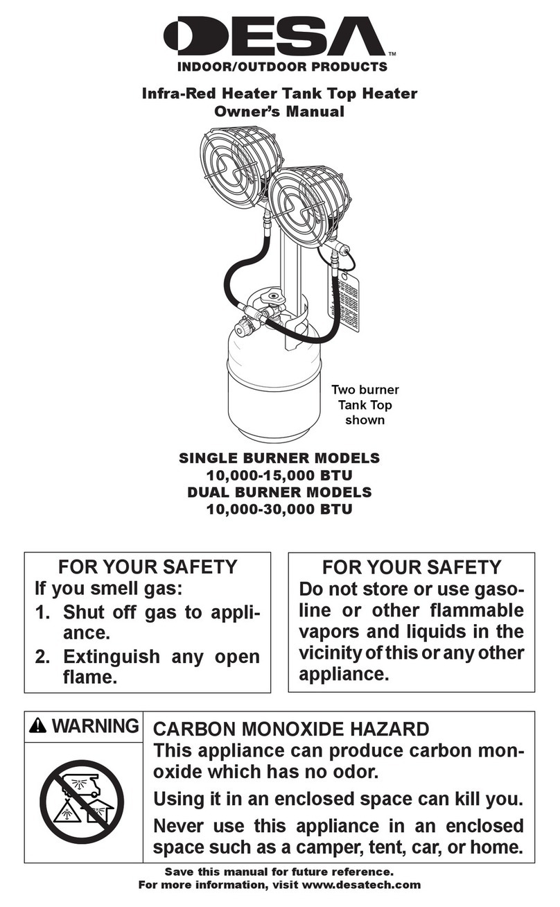
THERMOBILE IMAC 4000 GAS US User manual


Table of contents
Other THERMOBILE Heater manuals
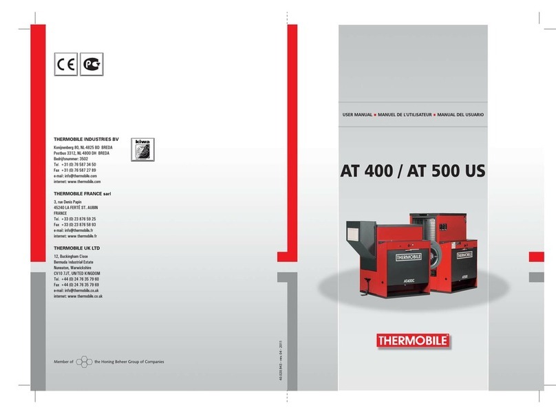
THERMOBILE
THERMOBILE AT 400 User manual

THERMOBILE
THERMOBILE Bio Energy 2 User manual
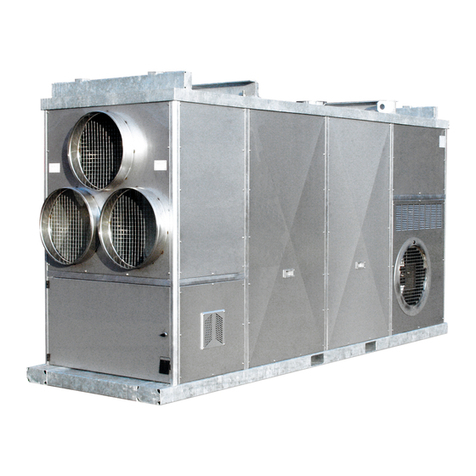
THERMOBILE
THERMOBILE IMAC 4000 User manual
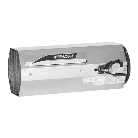
THERMOBILE
THERMOBILE AGA 45 User manual

THERMOBILE
THERMOBILE AT 306 User manual

THERMOBILE
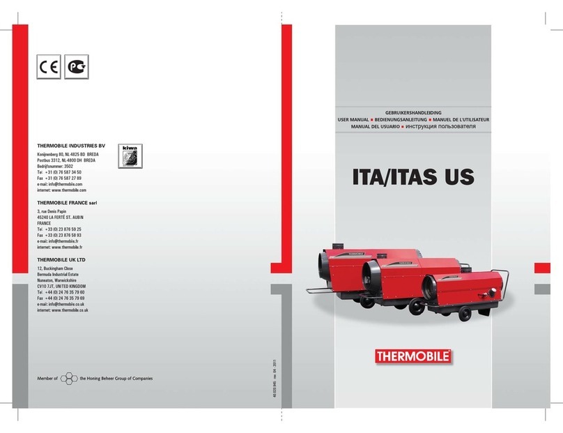
THERMOBILE Bio Energy Series User manual
THERMOBILE
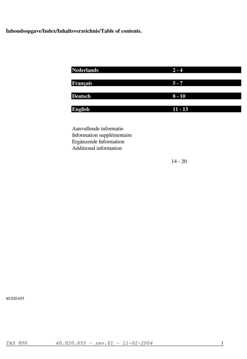
THERMOBILE ITA 30-US User manual

THERMOBILE
THERMOBILE AGA 100 User manual
THERMOBILE
THERMOBILE TAS 800 Installation manual
THERMOBILE
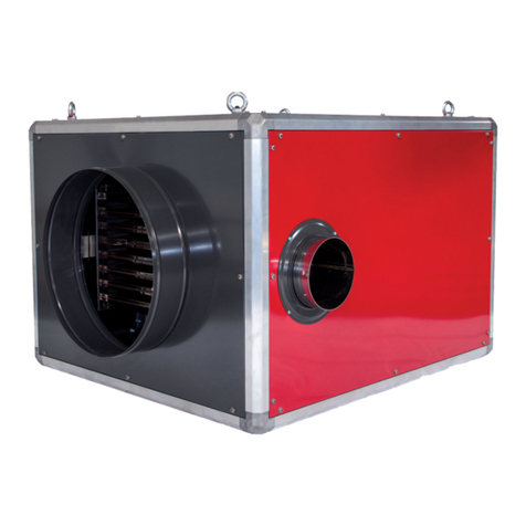
THERMOBILE IMAC User manual
THERMOBILE
THERMOBILE ISA 65 User manual

THERMOBILE
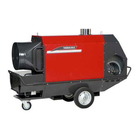
THERMOBILE IMAC 2000 PELLET User manual
THERMOBILE
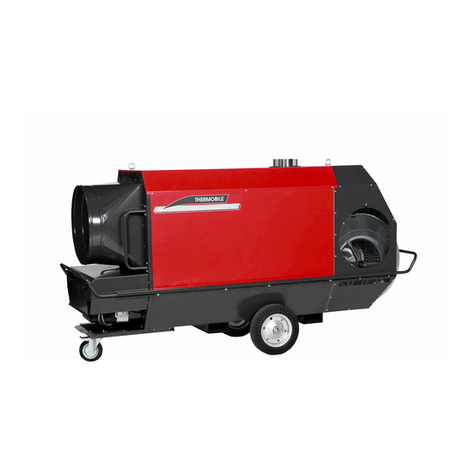
THERMOBILE IMA US Series User manual
THERMOBILE
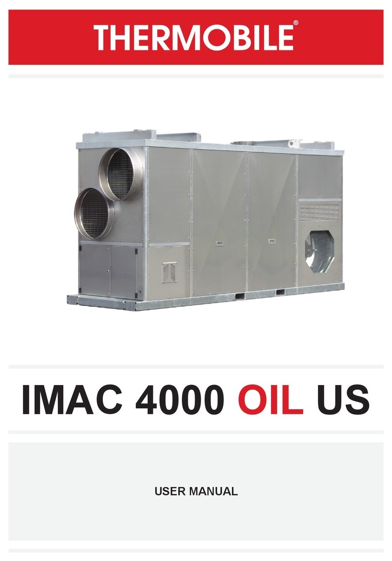
THERMOBILE IMAC 4000 OIL US User manual
THERMOBILE
THERMOBILE IMA User manual

THERMOBILE
THERMOBILE AGA 111 User manual
THERMOBILE
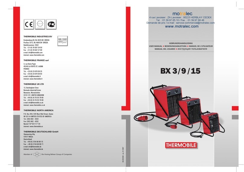
THERMOBILE BX 3 User manual

THERMOBILE
THERMOBILE Bio Energy Series User manual

THERMOBILE
THERMOBILE IFT-21 User manual
Popular Heater manuals by other brands

flowair
flowair ELIS G E 150 Technical documentation operation manual

BriskHeat
BriskHeat FGDH instruction manual

CHAPALA CHIMENEAS
CHAPALA CHIMENEAS Chimenea Medium quick start guide

Outwell
Outwell FUJI instruction manual

HeatStar
HeatStar F140625 Operating instructions and owner's manual

Helo
Helo Viki Series Installation and operating instruction

Argo
Argo DAKOTA operating instructions
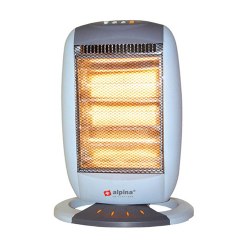
Alpina
Alpina SF-9353 Instructions for use
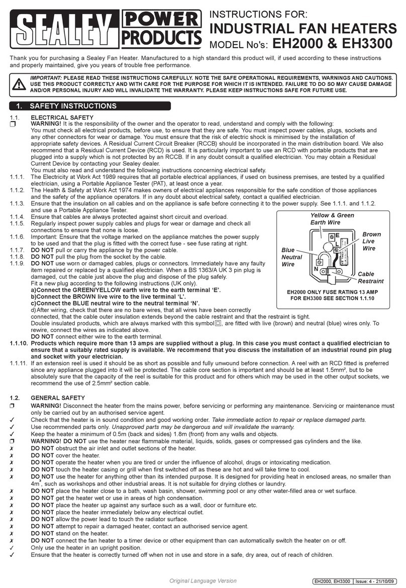
Sealey
Sealey EH3300 instructions
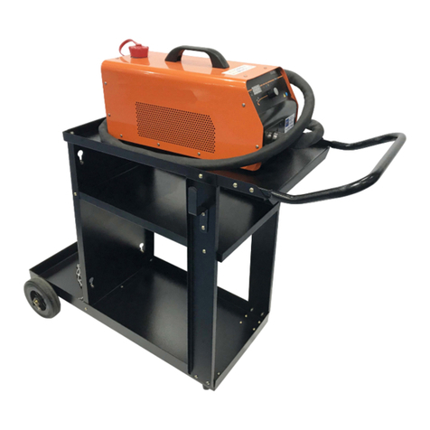
Butts of Bawtry
Butts of Bawtry DHI0044 Operating and maintenance manual

Goldair
Goldair SELECT GSFH150 operating instructions
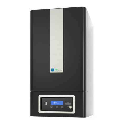
Eco Heating Systems
Eco Heating Systems CB 85 HW Installation, service and user manual
