manuals.online logo
Brands
  1. Home
  2. •
  3. Brands
  4. •
  5. TILLIG BAHN
  6. •
  7. Toy
  8. •
  9. TILLIG BAHN 96119 User manual

TILLIG BAHN 96119 User manual

Güterwagen
1
www.tillig.com www.facebook.com/tilligbahn 364249 / 18.11.2021
12
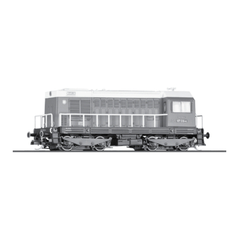
Diesellok • Diesel locomotive
Locomotive diesel • Dieselová lokomotiva
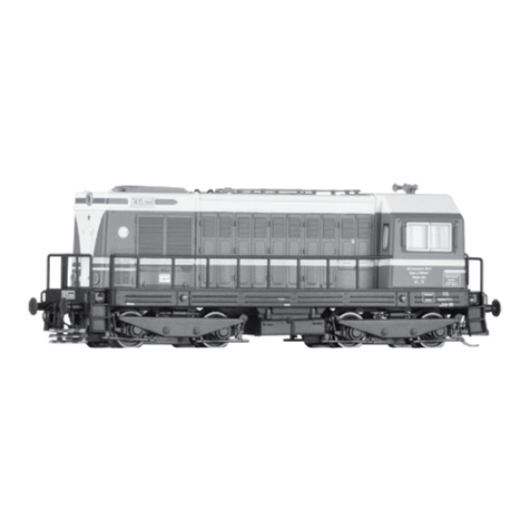
Spalinowóz V 60.0
(DE) Das Modell basiert auf dem Fahrwerk der V 60.0. Alle Achsen sind angetrieben und dienen der Stromabnahme. Das
Spitzen- und Schlusslicht wechselt mit der Fahrtrichtung. Das Modell verfügt über eine Decoderschnittstelle nach NEM 662.
Das Modell erreicht nach einer Einlaufzeit von ca. 20 Minuten in beide Fahrtrichtungen seine optimalen Fahreigenschaften.
Ab Werk ist das Modell ausreichend gefettet. Ein Nachfetten oder -ölen mit harz- und säurefreiem Fett oder Öl ist erst nach
ca. 100 Betriebsstunden zu empfehlen. Dazu geeignetes Fett ist unter TILLIG Art.-Nr. 08973 erhältlich. Die Reinigung der
Radschleifer und Radsätze zur Erhaltung der Kontaktgabe ist jedoch je nach Einsatz öfters zu empfehlen. Dazu geeignete
Reinigungsüssigkeit ist unter TILLIG Art.-Nr. 08977 erhältlich. Zum Ö󰀨nen des Modells sind die Vorbauten des Oberteiles
leicht zusammenzudrücken, um die Rastnasen aus dem Umlauf auszurasten.
(GB) The model is based on the chassis of the V 60.0. All the axles are driven and serve to pick up current. The headlight
and rear light changes with the direction of travel. The has a decoder interface according to NEM 662. The model achieves
its optimum driving characteristics after a running-in time of approx. 20 minutes in both directions. The model comes su󰀩-
ciently greased at delivery. Regreasing or oiling with acid-free and resin-free lubricant or oil is only necessary after approx.
100 operating hours. The suitable grease is TILLIG with the Item no. 08973. Depending on use, we recommend cleaning the
wheel contacts and wheel sets more often in order to preserve the contact mode. The suitable cleaning liquid is TILLIG with
the Item no. 08977. To open the model press the stems of the the upper part slightly together to unlatch the latching lugs
from the frame surrounding.
(FR) Le modèle se base sur le châssis de la V 60.0. Tous les essieux sont moteurs et servent à la prise de courant. Les feux
avant et arrière changement avec le sens de la marche. Le modèle dispose d’une interface de décodeur selon NEM 662. Après
une période de rodage d’env. 20 minutes dans les deux sens de marche, le modèle atteint ses caractéristiques optimales de
marche. Le modèle est su󰀩samment graissé à l’usine. Nous recommandons de regraisser ou rehuiler avec une graisse ou
une huile exempte de résine et d’acide après env. 100 heures de service. La graisse adaptée est disponible chez Tillig, réf.:
08973. Cependant, nous recommandons de nettoyer les capteurs de roue et les essieux plus souvent et selon l’utilisation
pour maintenir le contact. Le liquide de nettoyage adapté est disponible chez Tillig, réf.: 08977. Pour ouvrir le modèle, presser
légèrement les avancées de la partie supérieure pour détacher les taquets de blocage de leur encoche.
(CZ) Tento model vychází z podvozku V 60.0. Všechny nápravy jsou hnané a slouží k odběru proudu. Čelní a koncové světlo
se přepíná podle směru jízdy. Model je vybaven rozhraním dekodéru dle NEM 662. Po záběhu trvajícím zhruba 20 minut v
obou směrech dosáhne model svých optimálních jízdních vlastností. Z výroby je model již dostatečně namazán. Domazání
nebo olejování mazacím tukem nebo olejem bez obsahu pryskyřic a kyselin se doporučuje teprve po cca 100 provozních
hodinách. K tomu účelu je vhodný mazací tuk TILLIG Art.-č. 08973. Čištění kontaktů kol a soukolí se však pro zachování
dobrého kontaktu doporučuje podle způsobu provozu i častěji. K tomu účelu je vhodná čisticí kapalina TILLIG Art.-č. 08977.
Pro otevření modelu zlehka stiskněte k sobě výstupky horní části, aby se uvolnily zámky z obvodu rámu.
(PL) Model opiera się na podwoziu V 60.0. Wszystkie osie są napędzane i służą do poboru prądu. Światło czołowe i końco-
we zmieniają się zależni od kierunku jazdy. Model wyposażony jest w złącze dekodera zgodne z NEM 662. Model po ok. 20
minutach docierania osiąga optymalne właściwości jezdne w obu kierunkach jazdy. Model został dostatecznie nasmarowany
przez producenta. Powtórne smarowanie lub oliwienie za pomocą wolnego od żywic i kwasów smaru lub oleju zaleca się
dopiero po ok. 100 godzinach eksploatacji. Odpowiedni do tego celu smar dostępny jest pod nr art. TILLIG 08973. Częściej
jednak, zależnie od eksploatacji, zaleca się, dla zachowania zestyku, czyszczenie ślizgaczy kołowych i zespołów kół. Odpo-
wiedni do tego celu płyn czyszczący dostępny jest pod nr art. TILLIG 08977. Aby otworzyć model należy dobudówki części
górnej lekko ścisnąć, aby wyzębić noski zatrzasków z ramy.

(DE) Bitte beachten Sie: Für dieses TILLIG-Produkt gilt der gesetzliche Gewährleistungsanspruch von 24 Monaten ab
Kaufdatum. Dieser Gewährleistungsanspruch erlischt, wenn kundenseitige Eingri󰀨e, Veränderungen, Umbauten usw.
an dem Produkt erfolgen/vorgenommen werden. Bei Fahrzeugen mit eingebauter Schnittstelle, können Gewährleis-
tungsansprüche nur geltend gemacht werden, wenn das betre󰀨ende Fahrzeug im Lieferzustand (ohne eingebautem
Digitaldecoder, mit eingestecktem Entstörsatz) an den Fachhändler zurück gegeben wird.
(GB) Please note: This TILLIG product is subject to the statutory warranty entitlement of 24 months from the date of
purchase. This warranty claim expires if the product is interfered with, modied or converted after the point of time of the
customer acquiring ownership. Where vehicles have an integrated interface, claims for warranty can only be asserted if
the vehicle concerned is returned in an as-delivered state (without built-in digital decoder, with plugged-in interference
suppression kit).
(FR) Attention: Pour ce produit TILLIG, le droit de garantie légal de 24 mois à partir de la date d’achat s’applique. Ce
droit de garantie s’éteint si le client procède/a procédé à des interventions, des modications, des transformations, etc.
sur le produit. Pour les véhicules à interface intégrée, les droits de garantie ne peuvent être acceptés que si le véhicule
correspondant est restitué au revendeur dans l’état de livraison (sans décodeur numérique intégré, avec l’antiparasite
installé).
(CZ) Pro tento výrobek TILLIG platí zákonný záruční nárok 24 měsíců od data koupě. Tento záruční nárok
zaniká, pokud byly ze strany zákazníka na výrobku provedeny zásahy, změny, přestavby atd. U vozidel se zabudovaným
rozhraním mohou být záruky uplatněny jen tehdy, když bude předmětné vozidlo vráceno do odborné prodejny v
původním stavu (bez zabudovaného digitálního dekodéru, se zasunutou odrušovací sadou).
(PL)  dla niniejszego produktu TILLIG obowiązuje ustawowe roszczenie gwarancyjne,
wynoszące 24 miesiące od daty zakupu. Roszczenie gwarancyjne wygasa w sytuacji, gdy przeprowadzone zostaną w
produkcie zmiany lub klient dokona przebudowy produktu na własną rękę. W pojazdach z zabudowanym interfejsem,
roszczenia gwarancyjne mogą być podnoszone jedynie, gdy dany pojazd przekazany zostanie przedstawicielowi
handlowemu w stanie, jaki obowiązywał w momencie dostawy (bez zabudowanego dekodera cyfrowego, z osadzonym
zestawem odkłócającym).
Art.-Nr. / Item no. / Réf. / Art.-č. / Nr art.
96119 – Diesellok 270 155, Ep. III
"VEB Kalikombinat Werra" 91

Promenade 1, 01855 Sebnitz
Tel.: +49 (0)35971 / 903-45 •Fax: +49 (0)35971 / 903-19
(DE) Hotline Kundendienst • (GB) Hotline customer service • (FR) Services à la clientèle Hotline
(CZ) Hotline Zákaznické služby • (PL) Biuro Obsługi Klienta: 
(DE) Technische Änderungen vorbehalten! Bei Reklamationen wenden Sie sich bitte an Ihren Fachhändler.
(GB) Subject to technical changes! Please contact your dealer if you have any complaints.
(FR) Sous réserve de modications techniques! Pour toute réclamation, adressez-vous à votre revendeur.
(CZ) Technické změny vyhrazeny! Při reklamaci se obraťte na svého obchodníka.
(PL) Zastrzega się możliwość zmian technicznych! W przypadku reklamacji prosimy zgłaszać się do specjalistycznego sprzedawcy.

 When this product comes to the end of its useful life, you may not dispose of it in the ordinary
domestic waste but must take it to your local collection point for recycling electrical and electronic equipment. If you don’t know the location of
your nearest disposal centre please ask your retailer or the local council o󰀩ce.
 Tento produkt nesmí být na konci
svého užívání zlikvidován jako běžný domovní odpad, ale musí být zlikvidován např. ve sběrném dvoře. Prosím, zeptejte se vašeho obchodníka,
popř. na svém obecním úřadě o vhodném způsobu likvidace.

 Produkty oznaczone przekreślonym pojemnikiem
po zakończeniu użytkowania nie mogą być usuwane razem z normalnymi odpadami domowymi, lecz muszą być przekazywane do punktu zbie-
rania i recyklingu urządzeń elektrycznych i elektronicznych. Dzięki recyklingowi pomagają Państwo skutecznie chronić środowisko naturalne.
Prosimy zwrócić się do specjalistycznego sklepu lub do odpowiedniego urzędu w Państwa okolicy, aby dowiedzieć się, gdzie jest najbliższy punkt
recyklingu urządzeń elektrycznych i elektronicznych.

 À la n de sa durée de vie, ne pas éliminer ce produit avec les déchets ménagers
mais le remettre à un point de collecte pour le recyclage d’appareils électriques et électroniques. Veuillez vous adresser à votre revendeur ou à
l’administration communale pour connaître les points d’élimination compétents.
              -
       Dieses Produkt darf am Ende seiner Nutzungsdauer nicht über
den normalen Hausmüll entsorgt werden, sondern muss an einem Sammelpunkt für das Recycling von elektrischen und elek-
tronischen Geräten abgegeben werden. Bitte fragen Sie bei Ihrem Händler oder der Gemeindeverwaltung nach der zuständigen Entsor-
gungsstelle.
14+
2
•  ••

(DE) Zur weiteren Detaillierung des Modells liegen einige
Teile zur Selbstmontage bei. Die Teile sollten mit einem
Tropfen Sekundenkleber gesichert werden.
(GB) Enclosed are some parts that you can assemble
yourself to further enhance the model. The parts
should be secured with a drop of superglue.
(FR) Pour apporter d’autres détails au modèle,
quelques pièces à monter soi-même sont jointes.
Il est conseillé de xer les pièces avec une goutte
de colle rapide.
(CZ) Pro rozšíření detailů je k modelu přibaleno
příslušenství, které lze volitelně nasadit podle
použití modelu.Komponenty připevněte kapkou
vteřinového lepidla.
(PL) Możliwość wzbogacenia modelu w kolejne
detale dają załączone akcesoria do montażu we
własnym zakresie. Części należy umocować za
pomocą kropli kleju błyskawicznego.
D
I
K
A
J
K
A
K
J
K
H
B B
C
B
F
B
C
E
E
F
D(DE) Antenne
(GB) Antenna
(FR) Antenne
(CZ) Anténa
(PL) Antena
(DE) Bremsschläuche
(GB) Brake hoses
(FR) Tuyaux de frein
(CZ) Vzduchové hadice
(PL) Węże gumowe sprzęgu hamulcowego
C
A(DE) Gri󰀨stange, Führerhaus
(GB) Handle bar, Driver’s cab
(FR) Barre de maintien, Cabine du conducteur
(CZ) Madlo, Kabina strojvedoucího
(PL) Poręczv, Budka maszynisty
B(DE) Gri󰀨stange, Umlauf-Tritt
(GB) Handle bar, Running board-Tread
(FR) Barre de maintien, Circonférence-Marche
(CZ) Madlo, Rám-Stupátko
(PL) Poręcz, Przewody cyrkulacyjne kotła-Schodek
(DE) Gri󰀨stange, links, Umlauf
(GB) Handle bar, left, Running board
(FR) Barre de maintien, gauche, Circonférence
(CZ) Madlo, levý, Rám
(PL) Poręcz, lewo, Przewody cyrkulacyjne kotła
E
(DE) Gri󰀨stange, rechts, Umlauf
(GB) Handle bar, right, Running board
(FR) Barre de maintien, droite, Circonférence
(CZ) Madlo, pravý, Rám
(PL) Poręcz, prawo, Przewody cyrkulacyjne kotła
F
(DE) Gri󰀨stange, Oberteil
(GB) Handle bar, Top part
(FR) Barre de maintien, Partie supérieure
(CZ) Madlo, Svršek
(PL) Poręcz, Część górna
G
(DE) Gri󰀨stange, vorn
(GB) Handle bar, front
(FR) Barre de maintien, avant
(CZ) Madlo, přední
(PL) Poręcz, przód
H
(DE) Gri󰀨stange, hinten
(GB) Handle bar, rear
(FR) Barre de maintien, arrière
(CZ) Madlo, zadní
(PL) Poręcz, tył
I
(DE) Gri󰀨stange (Motor)
(GB) Handle bar (Motor)
(FR) Barre de maintien (Moteur)
(CZ) Madlo, zadní (Motor)
(PL) Poręcz (Silnik)
J
(DE) Gri󰀨stange 3,5 mm
(GB) Handle bar 3,5 mm
(FR) Barre de maintien 3,5 mm
(CZ) Madlo, zadní 3,5 mm
(PL) Poręcz 3,5 mm
K
11

Die komplette Bedienungsanleitung für die Digitalisierung nden Sie auf unserer Homepage 

The complete operating instructions for digitization can be found on our homepage 
(FR) 
Le mode d'emploi complet pour la numérisation se trouve sur notre page d'accueil 
(CZ) 
Kompletní návod k digitalizaci najdete na naší domovské stránce 
(PL) Z
Pełną instrukcję obsługi digitalizacji można znaleźć na naszej stronie internetowej 
•  • •  • 
(DE) Das Modell ist mit einer Schnittstelle nach NEM 662 ausgestattet. Informationen
zur Digitalisierung nden sie auf unserer Homepage.
(GB) The model is equipped with an interface according to NEM 662 S. Information
about digitization can be found on our homepage.
(FR) Le modèle est équipé d'une interface selon NEM 662. Informations sur la numéri-
sation peut être trouvé sur notre page d'accueil.
(CZ) Model je vybaven rozhraním podle NEM 662. Informace o digitalizaci naleznete na
naší domovské stránce.
(PL) Model jest wyposażony w interfejs zgodny z NEM 662. Informacja o digitalizacji
można znaleźć na naszej stronie głównej.

3

Die folgende Funktionszuordnung ist werkseitig verfügbar:
Nur F0 schaltet Frontbeleuchtung ein/aus, richtungsabhän-
gig (nur WEISSE leuchten in Fahrtrichtung)
 schaltet Schlussleuchten ein/aus, richtungsabhängig
(nur ROT leuchtet auf der der Fahrtrichtung entgegengesetz-
ten Seite)
   Ein-/Ausschalten von Frontleuchten und Schluss-
leuchten, richtungsabhängig (WEISSE Lichter in Fahrtrich-
tung und ROTE Lichter in Gegenrichtung zur Fahrtrichtung)

Schaltet das aufgeblendete rechte Licht weiss ein/aus, kombi-
niert mit weiß/rot oder nur weißen Lichtern. Das aufgeblendete
Licht kann nur in Kombination mit F0 eingeschaltet werden
F3 Schaltet Rangierlicht 1 ein (rechts unten leuchtet WEISS
auf der rechten Seite der Lokomotive, von der Kabine aus ge-
sehen, auf beiden Seiten der Lokomotive, unabhängig von der
Fahrtrichtung). Dies entspricht dem alten Rangierlichtschema.
Diese Funktion überschreibt alle anderen Funktionen außer
F2, da sie die zweithöchste Priorität hat.
Schaltet Rangierlicht 2 ein (alle WEISSEN leuchten auf bei-
den Seiten der Lok unabhängig von der Fahrtrichtung). Dies
entspricht dem modernen Rangierlichtschema. Diese Funkti-
on überschreibt alle anderen Funktionen, da sie die höchste
Priorität hat
F5 Kabinenlicht ein-/ausschalten (Option)

The following function mapping is available as factory defaults:
  Switches On/O󰀨 front light, direction dependent
(only WHITE lights in the direction of travel)
 Switches On/O󰀨 rear light, direction dependent (only
RED lights in the opposite side to the direction of travel)
 Switches On/O󰀨 front light and rear light, direction
dependent (WHITE lights in the direction of travel and RED
lights in the opposite side to the direction of travel)

Switches On/O󰀨 High Beam combined with White/Red or
only White lights. The high beam can be turned on only in
combination with F0
F3 Switches On shunting light 1 (lower right WHITE light on,
on the right side of the locomotive viewed from the cab, on
both sides of the locomotive independent of direction of tra-
vel). This is equivalent to the old type Shunting Light Sche-
me. This function overrides all other functions except F2,
since it has the second highest priority.
Switches On shunting light 2 (all WHITE light on, on both
sides of the locomotive independent of direction of travel).
This is equivalent to the modern Shunting Light Scheme. This
function overrides all other functions, since it has the highest
priority.
F5 Turn On/O󰀨 cabin light (Option)
10

Der in die Hauptplatine der V60-Lokomotive ECU und Licht-
decoder steuert die 10 (+1) im Lokomotivengehäuse instal-
lierten LEDs an. Der ECU mit Lichtdecoder kann von jedem
Next18/Next18S-Lokdecoder mit SUSI-Schnittstelle gesteuert
werden, die mit SUSI Version 1.0 oder höher kompatibel ist.
Er ist kompatibel mit 5V- oder 3,3V-Logikpegeln an der SU-
SI-Schnittstelle. Für den ECU mit Lichtdecoder ist die SUSI
SLAVE-Adresse 3 werkseitig eingestellt. Diese SLAVE-Ad-
resse kann geändert werden, indem der Wert von CV897
geändert wird, nur wenn keine anderen SUSI-Geräte an den
SUSI-Bus/die SUSI-Schnittstelle angeschlossen sind. Die
Standard-SUSI-SLAVE-Adresse 3 wurde für den integrierten
ECU mit Lichtdecoder ausgewählt, da einige Next18S-Loko-
motiven Sounddecoder (wie der Uhlenbrock 33200) interne
SUSI-Soundmodule verwenden, die normalerweise für die
1/2 SUSI-SLAVE-Adressen konguriert sind. Auf diese Weise
kann ein Konikt auf der SUSI-Schnittstelle/ dem SUSI-Bus
vermieden werden.

The ECU and light decoder integrated in the V60 locomotive
main circuit board drives the 10 (+1) LEDs installed in the lo-
comotive housing. The ECU can be controlled by any Next18/
Next18S locomotive decoder with SUSI interface compatible
with SUSI version v 1.0 or above. It is compatible with 5V or
3,3V logic levels on the SUSI interface. The ECU light de-
coder has the SUSI SLAVE address 3 set as factory default.
This SLAVE address can be modied changing the value of
CV897, only when no other SUSI devices are connected to
the SUSI bus/interface. The default SUSI SLAVE address 3
has been chosen for the ECU light decoder, because some
Next18 locomotive sound decoders (like the Uhlenbrock
33200) uses internal SUSI Sound modules, which are usually
congured to the 1/2 SUSI SLAVE addresses. In this way any
conict on the SUSI interface/bus can be avoided.
6
13
12
7
10
15
2
9
16
14
1a
5
8
11
2
1b
1a
2
2
1b
4
20
21
22
23
17
18
19
3
25
24
26
9
6
(DE) Die Lok-Betriebsnummern der Artikel wechseln unter Umständen bei Neuproduktion. Ersatzteile zu
den Art.-Nr. tragen die jeweils in der Produktion bendlichen Betriebsnummern. Ersatzteile mit älteren Betriebsnummern
nur solange Vorrat reicht.
(GB) The locomotive operating numbers of the articles can potentially change in the event of new production
runs. Spare parts for the article number bear the operating numbers that are respectively in production. Spare parts with older
operating numbers are only available while stocks last.
(FR)  Les numéros d’exploitation de locomotives des articles changent parfois lors d’une nouvelle production. Les
pièces de rechange relatives au n° art. portent respectivement les numéros d’exploitation se trouvant en production. Pièces de
rechange avec des numéros d’exploitation plus anciens jusqu’à rupture du stock.
(CZ)  Provozní číslo lokomotivy u tohoto artiklu se může změnit podle okolností nové výroby. Náhradní díly jsou k
dispozici k tomuto kat. číslu, které je právě ve výrobě. Náhradní díly Ke starším typům jsou pouze do té doby, dokud vystačí
skladové zásoby.
(PL)  Numery części lokomotywy mogą się zmieniać wraz z nową produkcją modelu. Części zamienne dla danego
numeru artykułu za każdym razem mają numery przyjęte z produkcji. Części zamienne ze starymi numerami części są dostępne
tylko do wyczerpania zapasu.
!



Pu󰀨er, ballig
Pu󰀨er, ach
Gri󰀨stange (Pu󰀨erbohle)
Litze
Leiterplatte
Schraube 2,2x4,5
Blende
Unterlage 10x13
Motor, vollst.
Achse Dm 1,0x8,4
Zahnrad z 18/10
Zahnrad z 25
Luftkessel
Radschleifer, li., mont.
Radschleifer, re., mont.
Bodenverkleidung
Kurbelzapfen, kurz
Kuppelstange, li.
Kuppelstange, re.
Kupplungsfeder
Kupplungsaufnahme
Kupplung
Senkschraube 1,8x4
Blindwelle, mont.
Zwischenrad
Kuppelradsatz
Entstörleiterplatte
Zurüstteile (o.Abb.)
(GB) Description
Bu󰀨er, spherical
Bu󰀨er, at
Handlebar (bu󰀨er beam)
Braid
Circuit board
Screw 2,2x4,5
Screen
Underlay 10x13
Motor, complete
Axle Dm 1,0x8,4
Gear wheel 18/10 teeth
Gear wheel 25 teeth
Air tank
Wheel contact, left, mounted
Wheel contact, right, mounted
Base cover
Crankshafts, short
Coupling rod, left
Coupling rod, right
Coupling spring
Coupler pocket
Coupling
Countersunk screw 1,8x4
Blind shaft, mounted
Idle wheel
Coupled wheel set
Interference supp. circuit board
Accessory parts (w/o illustr.)
(FR) Description
Tampon, en forme de balle
Tampon, plat
Barre de maintien (traverse porte-tampons)
Tresser
Carte de circuits imprimés
Vis 2,2x4,5
Cache
Support 10x13
Moteur, complète
Essieu Dm 1,0x8,4
Roue dentée d18/d10
Roue dentée d25
Réservoir à air
Capteur de roue, gauche, montée
Capteur de roue, droite, montée
Recouvrement de sol
Maneton de manivelle, courte
Barre de traction, gauche
Barre de traction, droite
Ressort de couplage
Logement d’attelage
Attelage
Vis à tête conique 1,8x4
Arbre aveugle, montée
Roue intermédiaire
Essieu couplé
Circuit imprimée antiparasite
Pièces d’équipeme.(sans illustr.)


2
3

5

7
8











20

22
23

25

-
Diese CV-Werte müssen geändert werden, um den TIL-
LIG-Decoder für den Betrieb der elektrischen Kupplung mit
dem ECU und Lichtdecoder der Hauptplatine der V60-Loko-
motive einzurichten.
        -

These CV values must be changed to set up the TILLIG de-
coder for electrical coupler operation with the ECU and light
decoder of the V60 locomotive main board.
Bitte beachten Sie: Diese Einstellung wird für den TIL-
LIG-Decoder benötigt.
Please note: These setting are needed for the TILLIG de-
coder.



Bitte beachten Sie: Die Polarität der elektrischen Kupplung
ist kritisch. Daher ist es wichtig, welcher Draht mit dem AUX1
und welcher mit dem V+ verbunden ist. Sie können es mit
einer normalen 12 V Gleichstromversorgung testen.
 Legen Sie die Spannung für eine sehr kurze
Zeit an die elektrische Kupplung, da sie sonst verbrannt wer-
den könnte. Halten Sie den Elektrischenkuppler in einer nor-
malen Position, da er in der Lok montiert wird. Wenn Sie den
Pluspol der Gleichstromversorgung an das richtige Kabel an-
schließen, steigt der Elektrischenkuppler in die obere Rich-
tung an. Dieser Draht muss mit dem V+ verbunden werden.
In der Abbildung auf der folgenden Seite nden Sie das
Installationsbeispiel für 2 elektrische Kupplungen, eine für
die Vorderseite der Lokomotive und eine für die Rückseite
(Beispiel 1). Die in diesem Handbuch beschriebenen CV-Ein-
stellungen für beide Decodertypen gelten für die Installation
eines einzelnen elektrischen Coulpers. Wenn Sie 2 separate
elektrische Kupplungen installieren möchten, befolgen Sie
bitte die CV-Einstellungen des Handbuchs für gebrauchte
Decoder. Zwei elektrische Kupplungen können an einem ein-
zigen Ausgang installiert werden (z. B. AUX1). Diese sollte
an AUX1 und V+ angeschlossen werden (Beispiel 2).

Please note: The polarity of the coupler is critical. So it is
important which wire is connected to AUX1 and which to V+.
You can test it on a standard 12 V DC power supply.
Apply voltage to the coupler for a very short time,
otherwise it could be burned.
Keep the coupler in a normal position as it will be mounted
in the locomotive. If you connect the positive terminal of the
DC power supply to the correct cable, the coupler rises in
the upper direction. This wire has to be connected to the V+.
In the illustration on the following page you can nd the in-
stallation example of 2 electrical couplers, one for the front
side of the locomotive, one for the rear side (Example 1).
The CV settings for both decoder type described in this ma-
nual are given for installation of one single electrical coul-
per. If you would like to install 2 separate electrical couplers,
please follow the CV settings of the used decoders manual.
Two electrical couplers can be installed to one single output
(AUX1 for example). The should be wired togehter to AUX1
and V+ (Example 2).
Notwendige Einstellungen Necessary settings




2
3

5

7
8











20

22
23

25

(CZ) Popis
Nárazník, vypouklý
Nárazník, plochý
Madlo (čelník)
Splétaný kabel
Deska s plošnými spoji
Šroub 2,2x4,5
Kryt
Podložka 10x13
Motor, kompletní
Náprava Dm 1,0x8,4
Ozubené kolo z18/z10
Ozubené kolo z25
Vzdušník
Kontakty kol, levý, namontovat
Kontakty kol, pravý, namontovat
Kryt podlahy
Klikový čep, krátké
Spojovací tyč spřáhla, levý
Spojovací tyč spřáhla, pravý
Spojovací pružina
Hnízdo spřáhla
Spřáhlo
Zápustný šroub 1,8x4
Slepý hřídel, namontovat
Mezikolo
Kola
Deska tištěného spoje
Příslušenství (bez zobrazení)

Zderzak, baryłkowaty
Zderzak, płaski
Poręcz przy (buforach)
Lica
Płytka drukowana
Śruba 2,2x4,5
Zaślepka
Podstawa 10x13
Silnik, kompletny
Oś Dm 1,0x8,4
Koło zębate z18/z10
Koło zębate z25
Powietrznik
Ślizgacz kołowy, lewo, zmontowana
Ślizgacz kołowy, prawo, zmontowana
Pokrycie podłogi
Czop korbowy, krótka
Drążek sprzęgający, lewo
Drążek sprzęgający, prawo
Spojovací pružina
Uchwyt sprzęgu
Sprzęg
Śruba z łbem 1,8x4
Wał ślepy, zmontowana
Koło pośrednie
Zestaw kołowy dowiązany
Płytka przeciwzakłóceniowa
Części dodatkowe (bez rys.)


382050










200275









202238
200257
202237



8


Diese CV-Werte müssen geändert werden, um einen gene-
rischen TILLIG-Decoder für den Betrieb mit dem ECU und
Lichtdecoder der Hauptplatine der V60-Lokomotive einzu-
richten.


These CV values must be changed to set up a generic
TILLIG decoder for the operation with the ECU and light de-
coder of the V60 locomotive main board.
Bitte beachten Sie: Diese Einstellung wird für den

benötigt.
Please note: These setting are needed for the -

Notwendige Einstellungen Necessary settings
Necessary settings
Notwendige Einstellungen
•  • •  • 
(DE) Das Modell ist mit einer Steckschnittstelle nach NEM 662 ausgestattet. Die Schnittstelle wird nach Abnehmen des
Oberteiles, wie im vorigen Abschnitt beschrieben, zugänglich.
(GB) The model is equipped with a plug-in interface according to NEM 662. This interface becomes accessible following the
removal of the upper part, as described in the previous section.
(FR) Le modèle est équipé d’une interface à encher selon NEM 662. Après retrait de la partie supérieure, l’interface est
accessible comme décrit dans la partie précédente.
(CZ) Model je vybaven rozhraním konektoru dle NEM 662. Rozhraní se zpřístupní sundáním horní části vozu, jak je uvedeno
v předchozí kapitole.
(PL) Model wyposażony jest w złącze wtykane wg NEM 662. Złącze dostępne jest po zdjęciu części górnej, jak opisano w
poprzednim akapicie.
(DE) Eventuelle Reklamationsansprüche betre󰀨end der Lokomotive ohne eingebauten Digitaldecoder geltend machen!
(GB) Assert any applicable complaint claims concerning the locomotive if it does arrive without an installed digital decoder!
(FR) Formulation de droits éventuels à réclamation concernant la locomotive sans décodeur numérique intégré!
(CZ) Pro případné uplatnění reklamačních nároků musí být lokomotiva bez zabudovaného digitálního dekodéru!
(PL) Ewentualne roszczenia reklamacyjne dotyczące lokomotywy należy wnosić bez zamontowanego dekodera cyfrowego!

      


In der folgenden Abbildung sind die Verbindungspunkte für
externe und die internen Standardverbindungen markiert.
Über diese Punkte hat der Benutzer die Möglichkeit, zusätz-
liche Geräte an den installierten Next18-Decoder anzuschlie-
ßen. In diesem Fall ist eine ordnungsgemäße Konguration
des Decoders erforderlich.

In the illustration below the external and the standard inter-
nal connection points are marked. The user has the option
through these points to connect additional devices to the in-
stalled Next18 decoder. Proper conguration of the decoder
is required in this case.
Die Lötpads AUX1, AUX2, AUX3, AUX4, AUX5, AUX6, V+ und
GND sind die entsprechenden Pins der Next18-Schnittstelle.
AUX5 und AUX6 bleiben als logische Ausgänge für die weitere
Verwendung verfügbar. Die Lötpads AUX1 und AUX2 sind als
generische Ausgänge des Decoders verfügbar. Sie können
zum Anschluss externer Geräte wie elektrische Kupplungen,
Licht genutzt werden. Dies sind POWER-Ausgänge. Sowohl
AUX1 als auch AUX2 können als Power Pack-Steuerung
(SPP) konguriert werden, wenn der verwendete Lokdecoder
diese Art der Konguration zulässt. Diese können die Charge-
verbindung des verwendeten Power Pack mit dem erforderli-
chen logischen Status steuern.
The AUX1, AUX2, AUX3, AUX4, AUX5, AUX6, V+, GND sol-
der pads are the corresponding pins of the Next18 interface.
AUX5 and AUX6 remain available as logical outputs for
further use. The AUX1 and AUX2 solder pads are availab-
le as generic outputs of the decoder. They can be used for
connecting external devices as electrical couplers, lights.
These are POWER outputs. Both AUX1 and AUX2 can be
congured as Power Pack (SPP) control, if the used loco-
motive decoder allows this type of conguration. These can
control the Charge pin of the used power pack (SPP) with the
required logical state.
67
Der AUX2-Ausgang verfügt über eine integrierte Wechselrich-
terschaltung, die auch als Chargesteuerung verwendet wer-
den kann, wenn die Logik eine Inversion benötigt. Dies ist als
SPP-Charge Verbindungspunkt verfügbar. Der V+- und der
GND-Verbindungspunkt können hauptsächlich für die Power
Pack-Verbindung verwendet werden. Die Färbung der Verbin-
dungslinien in der Abbildung verwendet die Standardfarbkon-
vention der Decoder (nur auf unserer Homepage ersichtlich).
The AUX2 output has an on board inverter circuit, which can
be used also as a Charge Control, if the logic needs inver-
sion. This is available as the Charge SPP connection point.
The V+ and GND connection point are mostly usable for Po-
wer Pack connection.
The coloring of the connection lines in the illustration uses
the standard color convention of the decoders (only to see
on our homepage).
Bitte beachten Sie: Alle externen Geräte, die über die Haupt-
platine der Lok mit dem Decoder verbunden sind. Alle elektri-
schen Nennwerte (Leistung, Strom) der externen Geräte soll-
ten gemäß den Decoderparametern berücksichtigt werden.
Please note: all external devices connected to the decoder
through the main circuit board of the locomotive. All electri-
cal ratings (power, current) of the external devices should be
considered according to the decoder parameters.
    

Diese CV-Werte müssen geändert werden, um den Uhlen-
brock-Decoder für den ordnungsgemäßen Betrieb mit dem
ECU und Lichtdecoder der Hauptplatine der V60-Lokomotive
einzurichten.
Ab Software-Version 35


These CV values must be changed to set up the Uhlenbrock
decoder for the proper operation with the ECU and light de-
coder of the V60 locomotive main board.
Attention: since Software version 35
     

Diese CV-Werte müssen geändert werden, um den TIL-
LIG-Decoder für den Betrieb der elektrischen Kupplung mit
dem ECU und Lichtdecoder der Hauptplatine der V60-Loko-
motive einzurichten.
Ab Software-Version 35
        -

These CV values must be changed to set up the TILLIG de-
coder for electrical coupler operation with the ECU and light
decoder of the V60 locomotive main board.
Attention: since Software version 35
Notwendige Einstellungen Necessary settings

Other TILLIG BAHN Toy manuals

TILLIG BAHN BR 03 User manual

TILLIG BAHN

TILLIG BAHN BR 03 User manual

TILLIG BAHN 74910 User manual

TILLIG BAHN

TILLIG BAHN 74910 User manual

TILLIG BAHN 16590 User manual

TILLIG BAHN

TILLIG BAHN 16590 User manual

TILLIG BAHN 15150 User manual

TILLIG BAHN

TILLIG BAHN 15150 User manual

TILLIG BAHN 13350 User manual

TILLIG BAHN

TILLIG BAHN 13350 User manual

TILLIG BAHN 02712 User manual

TILLIG BAHN

TILLIG BAHN 02712 User manual

TILLIG BAHN 501279 User manual

TILLIG BAHN

TILLIG BAHN 501279 User manual

TILLIG BAHN 16571 User manual

TILLIG BAHN

TILLIG BAHN 16571 User manual

TILLIG BAHN 85631 User manual

TILLIG BAHN

TILLIG BAHN 85631 User manual

TILLIG BAHN 85323 User manual

TILLIG BAHN

TILLIG BAHN 85323 User manual

TILLIG BAHN Sleeping car User manual

TILLIG BAHN

TILLIG BAHN Sleeping car User manual

TILLIG BAHN 85182 User manual

TILLIG BAHN

TILLIG BAHN 85182 User manual

TILLIG BAHN H0-ELITE-ABW 9/12 User manual

TILLIG BAHN

TILLIG BAHN H0-ELITE-ABW 9/12 User manual

TILLIG BAHN Vindobona 2 User manual

TILLIG BAHN

TILLIG BAHN Vindobona 2 User manual

TILLIG BAHN 85183 User manual

TILLIG BAHN

TILLIG BAHN 85183 User manual

TILLIG BAHN H0-ELITE-DKW User manual

TILLIG BAHN

TILLIG BAHN H0-ELITE-DKW User manual

TILLIG BAHN 01762 User manual

TILLIG BAHN

TILLIG BAHN 01762 User manual

TILLIG BAHN 78223 User manual

TILLIG BAHN

TILLIG BAHN 78223 User manual

TILLIG BAHN 83161 User manual

TILLIG BAHN

TILLIG BAHN 83161 User manual

TILLIG BAHN BR 218 User manual

TILLIG BAHN

TILLIG BAHN BR 218 User manual

TILLIG BAHN 02624 User manual

TILLIG BAHN

TILLIG BAHN 02624 User manual

TILLIG BAHN 85326 User manual

TILLIG BAHN

TILLIG BAHN 85326 User manual

TILLIG BAHN 01757 User manual

TILLIG BAHN

TILLIG BAHN 01757 User manual

TILLIG BAHN 02625 User manual

TILLIG BAHN

TILLIG BAHN 02625 User manual

Popular Toy manuals by other brands

LEGO Elves 41174 Assembly manual

LEGO

LEGO Elves 41174 Assembly manual

Fisher-Price T5429 manual

Fisher-Price

Fisher-Price T5429 manual

MGA Entertainment Project MC2 BRYDEN'S GLOW STICK quick start guide

MGA Entertainment

MGA Entertainment Project MC2 BRYDEN'S GLOW STICK quick start guide

Accucraft PECKETT 0-4-0ST Operating instructions and owner's manual

Accucraft

Accucraft PECKETT 0-4-0ST Operating instructions and owner's manual

Dancing Wings Hobby 0.8 Tiger Moth instruction manual

Dancing Wings Hobby

Dancing Wings Hobby 0.8 Tiger Moth instruction manual

LEGO nexo knights 70320 manual

LEGO

LEGO nexo knights 70320 manual

Mega Construx Barbie DREAMTOPIA DPK95 instruction manual

Mega Construx

Mega Construx Barbie DREAMTOPIA DPK95 instruction manual

LeapFrog Count-Along Basket & Scanner instruction manual

LeapFrog

LeapFrog Count-Along Basket & Scanner instruction manual

Chipolino FLASH instruction manual

Chipolino

Chipolino FLASH instruction manual

LeapFrog Little Office Learning Center Parents' guide

LeapFrog

LeapFrog Little Office Learning Center Parents' guide

fantastic 75951 Assembly instructions

fantastic

fantastic 75951 Assembly instructions

LeapFrog Interactive Wooden Animal Puzzle instruction manual

LeapFrog

LeapFrog Interactive Wooden Animal Puzzle instruction manual

Brick Loot 10253 manual

Brick Loot

Brick Loot 10253 manual

Bemo RhB Ge 6/6 I operating instructions

Bemo

Bemo RhB Ge 6/6 I operating instructions

Kidzone Mercedes-Benz AMG GT quick start guide

Kidzone

Kidzone Mercedes-Benz AMG GT quick start guide

Pilot RC Extra 330SC Assembly manual

Pilot RC

Pilot RC Extra 330SC Assembly manual

DICKIE TOYS RC RUMBLE GRIMLOCK operating instructions

DICKIE TOYS

DICKIE TOYS RC RUMBLE GRIMLOCK operating instructions

INJUSA 20334 Instructions for use

INJUSA

INJUSA 20334 Instructions for use

manuals.online logo
manuals.online logoBrands
  • About & Mission
  • Contact us
  • Privacy Policy
  • Terms and Conditions

Copyright 2025 Manuals.Online. All Rights Reserved.