Tinkerine Studio Ditto Pro Parts list manual

Setup & Operations Manual
Version 1.0

Welcome
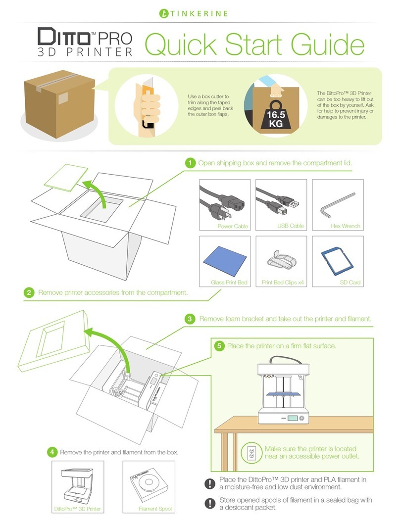
Congratulations on receiving your Ditto™Pro 3D Printer! This guide is designed to walk you through the unboxing
and setup process so you can start printing your 3D creations.
Got space? Save the
shipping box and
foam brackets for
printer storage and
shipping.
The DittoPro 3D Printer
can be too heavy to lift
out of the box by yourself.
Ask for help to prevent
injury or damage to the
printer.
16
KG
Unboxing 1

Step 1
Removing the Accessory Box
The accessory box is slotted into the top foam compartment
of the printer’s packaging. Remove the accessory box and
check to see that you have all of the following accessories.
Product Warranty Registration
Visit the online printer registration page
and follow the instructions to activate
your product warranty.
Locating the Product Serial Number
You can find your product serial number
located on the bottom panel in the back
of the printer. Your printer’s serial number
is required for warranty registration.
warranty-registration.tinkerine.com
Print Surface Clips x4
Glass Print Surface
USB Cable
Power Cable
SD Card Hex Wrench Inspection Certificate Test Print
Unboxing
REV#
2

3
Airflow
Allow passive airflow around the DittoPro 3D Printer. Avoid
obstructing the cooling fan intake located on the bottom
of the DittoPro 3D Printer.
Stability
Place the DittoPro 3D Printer on a flat and firm surface.
Excessive vibrations or shaking will affect print quality.
High Temperature
The printer’s nozzle can reach upwards of 200°C during
operation. Children and pets should be kept clear of
moving parts during the printing process.
Power
Ensure the printer is placed near an accessible power
outlet. Avoid plugging the printer into an overloaded
power bar as electrical shorts may cause the printer to
reboot during printing.
Unboxing
For long term storage, cover your printer to prevent
dust from accumulating on motion components.
Step 2
Removing the Shipping Bracket and Filament
Remove the top foam shipping bracket and take out the 3D
printing filament located on the side of the box. Remove the
DittoPro 3D Printer and place it upright on a firm flat surface.

Unboxing
Step 4
Turning on the Printer
Insert the female end of the power cord into the socket located on the back panel of the printer and the male end into the power socket. Turn on
the printer by flipping the power switch to the On position ( I ).
Store the removed clips and reuse when transporting the printer for shipping.
2x
Top View
Step 3
Removing the Gantry Clips
Located near the top of the DittoPro 3D Printer are two plastic gantry clips that prevent the extruder from moving freely during shipping. You
can remove the two gantry clips securing the extruder by pushing down the tabs on each end of the clips.
4

Loading the Filament
Step 5
Loading the Filament
Remove the spool of filament from the packaging and place it on the spool holder. Take the end of the filament from the spool and insert it into
the guide tube. Make sure the filament spool spins clockwise as the filament feeds into the guide tube.
Have a frim grip on the loose end of the filament when installing or
removing the spool from the printer. Letting go of the loose end before it is
secured may cause it to coil back and become tangled. These tangles are not
easily spotted, and may cause problems during printing.
For long term storage, retract and remove the filament from the printer. PLA
filament can become brittle over time as it is exposed to UV and moisture.
Store opened spools of filament inside the original packaging or in a sealed
bag with a desiccant packet.
The use of third-party filament will void the warranty on your DittoPro 3D Printer.
Spool Holder
Guide Tube
Removing
When removing filament, thread the loose end
through the storage holes on the spool.
Loading
When installing filament, thread the loose end through
the filament guide tube.
5

Loading the Filament
Step 6
Loading the Filament (Cont.)
Thread the filament through the guide tube (1). Push the tensioner button (2) down to make it easier to thread the filament through the drive
gear and into the hotend (3). Once the filament is inserted all the way down into the hotend, insert the guide tube into the top of the extruder
cap.
1
2
3
Trim off the tip of the filament with a pair of scissors if you are having trouble feeding the filament into the hotend.
6

Installing the Glass Print Surface
Step 7
Installing the Glass Print Surface
Place the glass print surface onto the bed with the blue painter’s tape side facing upward. The taped surface will act as an adhesion material
for the PLA plastic. To secure the print surface, attach the four print surface clips as shown below.
Replace any worn or damaged blue painter’s tape as needed to ensure that your prints stick properly during the printing process.
When replacing worn print surface tape, avoid overlapping strips of tape. The overlaps create an uneven print surface, which can
result in poor print adhesion.
7

Print Surface Calibration
Step 8
Print Surface Calibration
You’ll need to perform a print surface calibration for you printer to ensure the print surface is perfectly levelled in relation to the print nozzle.
Doing so allows the molten plastic to be laid down evenly and properly adheres onto the print surface during printing. It is recommended that
you perform the calibration process everytime the printer has been transported to a new location.
This is the Main Menu. From here, you can access the printer’s many functions.
To access the surface calibration wizard, turn the LCD dial until Wizard is
highlighted and Push the dial to make the selection.
Within Wizard, select Bed Level to begin the surface calibration process. Follow
the on-screen instructions to level the print surface.
Not sure if the bed calibration was done correctly?
Watch our online bed-leveling tutorial video by
scanning in the QR code on your phone or visiting
this link: https://youtu.be/GpMtpL-FfDM
8

Starting a Print
Step 9
Starting a Print
Follw the instructions below to begin your 3D print! Before you proceed, make sure you’ve installed the filament and performed the print surface
calibration.
If you haven’t inserted the SD card into the SD card slot beside the LCD screen,
the Print icon will display No Card.
Once the SD card is inserted, the icon will now display Print. Push down on the
LCD dial to enter the print selection menu.
In the print selection menu, all printable (.G format) files will be displayed along
with their estimated print time. Use the LCD dial to navigate and select the file
you would like to print. You can return to the previous screen at any time by
selecting Main located on the top of the list.
00:22
02:25
00:01
01:30
9

Ensuring Proper Print Adhesion
Important!
Ensuring Proper Print Adhesion
Whenever you begin a print, always check that the first layer of the print is properly stuck onto the blue painter’s tape. A properly levelled print
surface should have the extruded filament a bit squished. While the printer is printing the skirt (outer perimeter), observe the deposited filament
and make micro-adjustments with the thumbscrew if necessary.
Signs of nozzle too close to print surface:
(A) Inconsistent width along extrusion.
(B) Portion of the layer appear thin or
non-existent.
(C) Squshed filament causes areas to
overfill.
Signs of nozzle levelled to print surface:
(A) Consistent width along extrusion.
(B) Thickness appears consistent across
entire layer.
(C) Infill is even and joins up neatly with
the perimeter.
Signs of nozzle too far to print surface:
(A) Filament appear stringy and doesn’t
adhere to print surface.
(B) Infill doesn’t meet up with perimeter.
(C) Infill line doesn’t stick to other infill
lines.
TOO CLOSE TOO FARLEVELLED
10

Final Step
Print Removal
When your print is completed, it’s time to remove it from the print surface. While smaller prints can sometimes be easily removed by hand, we
recommend you to use a Print Removal Knife for removing prints.
After your print has completed, remove the glass print bed from the
printer and place down on a flat surface.
Using the Print Removal Knife, slowly wedge the knife between the
print and taped surface and lift upward. Repeat the process around
the print until you can easily pop the print off the print surface.
Print Removal 11

LCD Menu Settings
Additional LCD Menu Settings
Besides using the Print and Wizard option from the main menu, the Temp, Control, and Status menu offer several features that are essential to
the operation of the printer.
Temp
In the Temp menu, select Preheat to heat the hotend to printing temperature. The
hotend will remain heated until Cooldown is selected from the same menu or until
the printer is switched off.
Uses for the Preheat function:
1. Preheating the hotend prior to printing to reduce wait time.
2. Heat up the hotend for filament removal or manual extrusion.
Exit
Preheat
Cooled Down
Temp: 24 C
Status
The Status screen is the default screen display during printing. When the printer is
idle, this screen can be accessed by selecting Status from the home screen.
(A) Progress bar and percentage of current print.
(B) Current hotend temperature in degrees Celcius.
(C) Elaspsed time on current print.
(D) Time remaining on current print (Estimation may vary).
DittoPro ready.
A
B
C
D
Control
The Control menu contains different printer functions.
(A) Printer’s firmware version.
(B) Moves the extruder to the home position.
(C) Engages / disengages printer motors [For debugging].
(D) Heats up the hotend and extrudes a small length of filament.
(E) Turns on/off print surface cooling fans [For debugging].
(F) Toggles LCD dial sensitivity.
Enable
DialFan OnExtrude
Exit
A B C
D E F
12

Slicing Software
Slicing Software
Tinkerine Suite
If Tinkerine Suite isn’t already installed onto your computer, visit the software download page
at www.tinkerine.com/tinkerine-suite. Tinkerine Suite is available on the Windows and macOS
operating systems.
Tinkerine Suite is a ‘slicing’ software. With regards to 3D printing, this means that it will take a 3D models and slice it up into multiple layers that
are essentially instructions for the 3D printer to operate. While most of this magic happens on the backend, the user interface will allow for
adjustments like resolution, dimensions, and model traying.
13

Printer Specifications
Printer Specifications
PHYSICALS
Dimensions 37 x 49 x 43.6 cm (14.6 x 15.4 x 17.2 in)
Weight 10 kg (22 lb)
PRINTING
Build Volume 21.5 x 16 x 22 cm (8.4 x 6.3 x 8.7 in)
Filament Ø 1.75mm
Layer Resolution 50-300 microns (0.05-0.3 mm)
Material PLA Filament
Nozzle Ø 0.35mm
Technology Fused Filament Fabrication (FFF)
SOFTWARE
File Type STL, OBJ
OS Compatibility Windows, Mac
Software Tinkerine Suite
MECHANICAL
Body Aluminum Composite
Print Surface Glass (Adhesive material required)
Linear Motion Linear bearings, bronze bushings
Motor 1.8° step angle, 1/16 micro-stepping
ELECTRICAL
Connectivity USB (Firmware update), SD Card (Printing)
Consumption ~15W (idle), ~70W (operational)
Electronics RAMPS 1.4, AT mega 2560, A4988 stepper driver
Power Input AC 110-220V, 50-60 Hz
Power Output DC 12V, 15A
CERTIFICATION
cULus Passed
14

Notes 15
Other manuals for Ditto Pro
4
Table of contents
Other Tinkerine Studio 3D Printer manuals

Tinkerine Studio
Tinkerine Studio Ditto Pro User manual
Tinkerine Studio
Tinkerine Studio Ditto Pro User manual
Tinkerine Studio
Tinkerine Studio Ditto User manual
Tinkerine Studio
Tinkerine Studio LITTO User manual
Tinkerine Studio
Tinkerine Studio DittoPro-R Parts list manual
Tinkerine Studio
Tinkerine Studio Ditto Pro User manual

Tinkerine Studio
Tinkerine Studio Ditto Pro User manual

