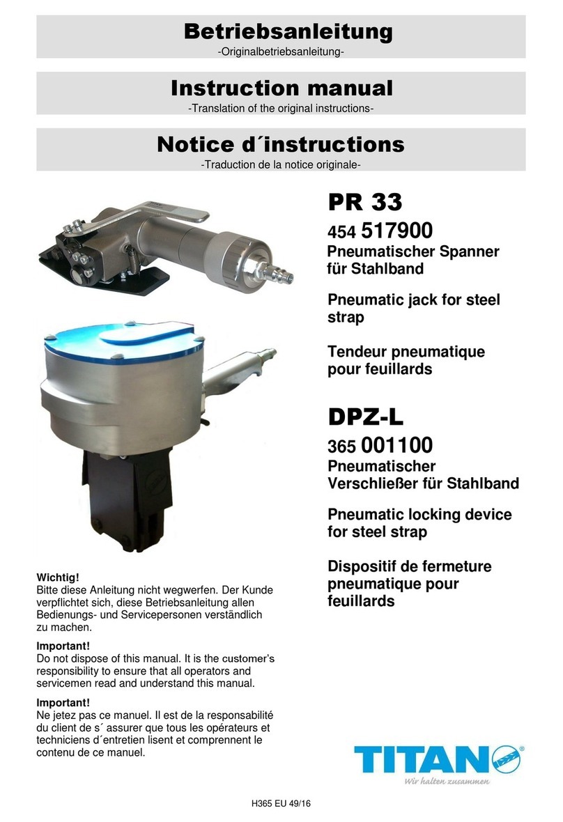
Titan sPR 33 User manual

sPR 33
454 517900
Pneumatic jack for steel
strap
DPZ-L
365 001100
32mm
Pneumatic locking device
for steel strap
Important!
Do not dispose of this manual. It is the customer‟s
responsibility to ensure that all operators and
servicemen read and understand this manual.

H365 EU 24/12
1.
General
These operating instructions are meant to facilitate becoming familiar with the units and their
intended use. These operating instructions include important notes on how the units can be
exploited safely, in a technically competent way and economically. Meeting instructions helps
avoid risks, reduce repairs and downtimes and increases the reliability and life of the units.
These operating instructions must be available at the location of the units. They must be read
and used by all persons working with the units. Those works especially include operation,
troubleshooting and maintenance.
Apart from the operating instructions and the regulations for the prevention of accidents
applicable in the user‟s country and at the place of location the acknowledged rules for
safety-related and technically competent working have to be observed.
Explanatory notes on the warning and instruction symbols:
Caution!
Is used in case of risks of life and health.
Attention!
Is used in case of risks which might cause damage to objects.
Note!
Is used for general notes as well as such whose disregard might
occur in the operational process.
1.1.
Notes on environmental protection
No substances detrimental to health, physical or chemical
substances are used for the manufacture of the units. Waste
disposal is subject to the applicable legal regulations.
PR33/DPZ-L

PR33/DPZ-L
H365 EU 24/12
2.
Technical data
2.1.
PR 33
Weight: 4,35 KG
Dimensions: l = 320 mm
b = 120 mm
h = 140 mm
Maximum air pressure: 6 bar
Tensioning force: 8000 N
Air consumption: 0.6 m³/min
Steel strap
Strap widths: 19, 25, 32 mm
Strap thickness: 0.8–1,0 mm
TITAN sealing sleeves: RSK, RSL

PR33/DPZ-L
H365 EU 24/12
2.2.
DPZ-L
Weight: 4.5 KG
Dimensions: l = 340 mm
b = 150 mm
h = 285 mm
Maximum air pressure: 6 bar
Seal: sleeve-type seal
TITAN sealing sleeves: RSK, RSL
Steel strap
Strap widths: 32 mm
Standard quality
Strap width: 0.8–1.0 mm
Tensile strength: to approx. 900 N/mm²
High-strength quality
Strap thickness: 0.8 mm
Tensile force: to approx. 1100 N/mm²

PR33/DPZ-L
H365 EU 24/12
3.
Safety Regulations
Intended Use
This device is intended for strapping round packages (profile bundles, pipes, coils, etc.).
The device was designed and built for safe operation during strapping.
The device is intended for strapping with steel packaging straps.
Possible misuse
The use of plastic straps is not allowed with this device.
Applied standards and specifications:
see EU declaration of conformity
Warranty and liability
TITAN Umreifungstechnik GmbH & Co. KG guarantees all strapping tools sold by the
company for a period of 6 months. The warranty covers all defects that can be
demonstrated to result from faulty craftsmanship or defective materials.
Wear parts are excluded from the warranty.
Warranty and liability claims shall be excluded if they are due to one or more of the following
causes:
Misuse of the tool.
Incorrect assembly, commissioning, operation and maintenance ofthe tool.
Operation of the tool with improper safety and protective devices.
Failure to comply with the information in the operating manual.
Unauthorized structural modifications to the tool.
Insufficient monitoring of tool parts that are subjectto wear.
Improper repairs.
The manufacturer reserves the right to make changes to the scope of delivery at any time for
the purpose of improving the product.

PR33/DPZ-L
H365 EU 24/12
Failure to comply with the following safety instructions, in addition to errors in
handling the device, can result in serious injuries.
Be informed!
Read the operating manual carefully before using the device
Protect yourself!
Always wear eye, face and hand protection (cut-resistant gloves)
when working.
Attention!
Strap flies outward!
When cutting the strap, hold the top part firmly and stand to the
side.
Attention!
The lower part of the strap will fly outward.
Attention!
Strap can break!
The strap can break during tightening! Do not stand in the path of
the strap. Make sure that no one else is in the working area.
Caution!
Danger of crushing!
Do not insert fingers into the pulley area.
Caution!
Strap only objects to be packed!
Make sure that no hands or other body parts are between the strap
and the goods to be packaged.
Use only original TITAN replacement parts!
The use of parts other than original TITAN replacement parts will
void the warranty and all liability.
Use only lifting gear that complies with the safety regulations!

PR33/DPZ-L
H365 EU 24/12
Use only original TITAN closure sleeves!
Do not exceed air pressure!
Never exceed the max. permissible air pressure of 6 bar.
Use original connection coupling.
Use only connection couplings that comply with the safety
regulations.
Do not use gas or compressed air cylinders!
Do not connect the tool to a gas or compressed air cylinder.
The use of straps other than those recommended can result in
broken straps during the tightening process and insufficient
strapping. Use only corresponding quality products from
TITAN!
This device may be operated only by personnel who have been
trained accordingly. Please consult your TITAN packing
consultant if you have any questions about this.
Workplace
Always maintain an orderly workplace. A disorderly workplace
can cause accidents. When operating the crimper, make sure
that you are in a well-braced position in order to maintain
optimum balance and prevent the risk of falling.
Never operate the tool in an awkward working position!
Maintenance
In order to operate safely, the tool must be properlymaintained.
Check the condition of your tool regularly for defects or worn
parts. Never use a tool that has defects or worn parts.
Modifications to the tool are strictly prohibited. Failure to comply
with this regulation can result in serious injury.
max. 6,0 bar
Original
TITAN

PR33/DPZ-L
H365 EU 24/12
4.
Description of funvtions
4.1.
Compressed air port
The maximum distance between the compressed air port and the location of the
strapping unit should not exceed 5 m.
In no case it is allowed to run the tool without oil being in the
lubricator of the maintenance unit, as this would immediately
destroy the compressed air motor.
No warranty in this case!
It is recommended that the maintenance unit comprising 2 air outputs and made by the
TITAN company is used.
4.2.
Checking machines and tools beforecommissioning
Before any new application it is required that the units and their attachments are
checked for damage and completeness. Hoses –air supply for firm seat. Exclusively
use original TITAN spare parts (also see section 3).
4.3.
Commissioning
Connect hand-held units PR 33 and DPZ-L to the compressed air network
(max. air pressure 6 bar).
Motor and compressed air cylinders are lubricated by the oil mist of the compressed
air. Faultlessly prepared compressed air is therefore a prerequisite for a problem-free
operation of the units. This can only be met by a functionally safe 3/8“ maintenance unit
comprising water separator, pressure reducing valve including pressure gauge and
oiler.
The oiler must discharge sufficient oil, approx. 1 drop per strapping. The length of the
hose should not exceed 5 m. The inner diameter of the hose should as a minimum be
8 mm. Attention should be paid that the hose does not form loops in which oil could be
collected.
Choice of the lubricating oil: resin- and acid-free lubricating oil whose viscosity is
2-4° E at 50°.
Max. operating pressure 6 bar.
Attention! Risk of tearing strap! The strap can tear when the
operating pressure of 6.5 bar is exceeded. Tearing strap can result
in injuries to the operator.

PR33/DPZ-L
H365 EU 24/12
5.
Operating
1 1
Pull steel strap out of the dispenser through the
sealing sleeve and put it around the packing item.
Again slip the beginning of the strap through the
sealing sleeve and bend it.
2 2
Take the jack (PR 33) in your right hand and
open it by pressing the lever. Then slip it on the
steel strap from the right to the left acc. to the
photo. Release the lever and tension the steel
strap by turning the turning valve to the left. The
tension of the strap desired (max. 6 bar) is
achieved by the control of the air pressure on the
pressure gauge of the maintenance unit.
3 3
Position the pneumatic sealing tongs (DPZ-L) on
the sealing sleeve (as shown in the photo) and
notch the sealing sleeve by the actuation of the
joining lever. At the same time the joining lever
snaps in automatically. Releasing is done
automatically after the notching of the seal and of
the steel strap have been completed. Interruption
of the joining process is possible at any time by
pushing the STOP key.
During the sealing operation the air feed at the
tensioning jack must not be stopped (tensioning
jack is without self-locking device).

PR33/DPZ-L
H365 EU 24/12
4 4
Upon completion of the seal deposit the locking
device and tilt the jack, as shown in the photo,
upwards until the steel strap breaks before the
sealing sleeve.
Again, the air supply must not be stopped.
Then, turn off the air feed and separate the
tension jack from the steel strap again by
pressing the lever.
5 5
Sketch
Course of strap
The following picture shows a correctly carved seal.
Check the seals regular
for crackings on the sleeve and
for neat cutting edges.

PR33/DPZ-L
H365 EU 24/12
6.
Maintenance
6.1.
Change of the tensioning wheel
Loosen the 3 fastening screws (10) and
remove the bearing plate (9). The
tensioning wheel (42/55) can be
accessed and removed from the
transport shaft.
Mounting in reverse order.
6.2.
Setting the clearance
After the installation of the new
tensioning wheel (42/55) the clearance
between wheel and guide plate (40)
must be checked and, if required,
readjusted.
Setting is performed by means of the
setting screw (38). For that purpose,
loosen the counternut (39).
The clearance between the tensioning
wheel and the guide plate should
be 0,2 mm.
6.3.
Cleaning and maintenance
Dirt and abrasion impair the function of the units.
Therefore, all units should be air-cleaned with compressed air in the area of the strap
guidance, notching cutters, tensioning wheel and joints after being used und, following
that, be wetted with resin-free thin spray oil.
Tool inspection!
Perform a daily visual inspection of the outside of the unit. The early detection of
damaged parts extends the life of the unit. Replace all damaged parts immediately
with Original TITAN spare parts.

PR33/DPZ-L
H365 EU 24/12
7.
Spare parts list
7.1.
Exploded view PR 33
Screws being secured by
adhesives have a grey
background in the spare parts list
in the column “Remarks”.
42
55

PR33/DPZ-L
H365 EU 24/12
7.2.
Spare parts list PR 33
Pos.
Order no.
Description
Dimensions
Pcs.
Remarks
1
4545179 - 1
Worm
1
2
4545179 - 2
Dowel pin
4m6 x 12
4
3
4545179 - 3
Worm wheel
1
4
4545179 - 4
Gear cover
1
5
4545179 - 5
O-ring seal
45 x 1.5 B
1
6
4545179 - 6
Deep-groove ball bearing
16003
1
7
4545179 - 7
Cheese-head screw
M6 x 16
3
Loctite 242
8
4545179 - 8
Washer
S6
3
9
4545179 - 9
Bearing plate
1
10
4545179 - 10
Cheese-head screw
M6 x 25
3
Loctite 242
11
4545179 - 11
Washer
S6
3
12
4545179 - 12
Withdrawal sleeve
3 x 20
1
13
4545179 - 13
Sealing washer
20
1
14
4545179 - 14
Conveyance shaft
1
15
4545179 - 15
Key
A6 x 6 x 20
1
16
4545179 - 16
Pintle
1
18
4545179 - 18
Distance sleeve
1
19
4545179 - 19
Tension element
1
20
4545179 - 20
Articulated rail
1
21
4545179 - 21
Leg spring
1
22
4545179 - 22
Fitted bolt
M8 x 55
1
23
4545179 - 23
Nut
M8
1
24
4545179 - 24
Sprue
1
25
4545179 - 25
Cheese-head screw
M6 x 12
2
Loctite 242
26
4545179 - 26
Washer
S6
2
27
4545179 - 27
Tension spring
1
28
4545179 - 28
Beak
G 3/8" PK 9
1
Loctite 242
29
4545179 - 29
Quick-acting coupling
ARO
1
30
4545179 - 30
Withdrawal sleeve
5 x 24
1
31
4545179 - 31
Needle bearings
NK 2616
1
32
4545179 - 32
Wave washer
WS 81104
4
33
4545179 - 33
Axial needle collar
AXK 2035
2
34
4545179 - 34
Needle bush
DLF 1212
1
35
4545179 - 35
Needle bush
DL 1312
1
36
4545179 - 36
Needle bush
DLH 1816
1
37
4545179 - 37
Circlip
18 x 1
1
38
4545179 - 38
Hexagon bolt
M6 x 20
1
39
4545179 - 39
Nut
M6
1
40
4545179 - 40
Guide plate
1
41
4545179 - 41
Counter-sunk screw
M6 x 10
1
42
4545179 - 42
Idler
1
43
4545179 - 43
Nameplate
1
44
4545179 - 44
Groove pin
2
45
4545179 - 45
Centering bush
1
46
4545179 - 46
Turning sleeve
444392
1
50
4545179 - 50
Coupling plug
ARO
1
Loctite 242
51
4545179 - 51
Cap
D - 11 x 20
1
V = Wearing part
R = Replacement parts
I = Initial equipment
B = If necessary
O = Option

PR33/DPZ-L
H365 EU 24/12
Pos.
Order no.
Description
Dimensions
Pcs.
Remarks
52
4545179 - 52
Distance washer
1
53
4545179 - 53
Operating pressure plate
1
55
4545179 –55
Tensioning Wheel (HT)
1
I
500
4545179 - 500
Gearbox
1
510
4545179 - 510
Compressed air motor
520G5 RDS
1
511
4545179 - 511
Compressed air motor
520G5 RDS
1
R
V = Wearing part
R = Replacement parts
I = Initial equipment
B = If necessary
O = Option

PR33/DPZ-L
H365 EU 24/12
7.3.
Exploded view DPZ-L
Screws being secured by
adhesives have a grey
background in the spare parts list
in the column “Remarks”.

PR33/DPZ-L
H365 EU 24/12
7.4.
Spare parts list DPZ-L
Pos.
Order no.
Description
Dimensions
Pcs.
Remarks
1
3650002 –1
Piston rod
1
V
2
3650002 –2
Turcon-Glyd Ring
PT 0301400
1
3
3650002 –3
Piston
1
4
3650002 –4
Axial washer
AS821
2
5
3650002 –5
Cylinder screw
M8 x 20
1
6
3650002 –6
O –Ring
125 x 3
1
7
3650002 –7
Oval head screw
M8 x 16
4
8
3650002 –8
Thrust washer
S8
4
9
3650002 –9
Conical spring washer
8
1
10
3650002 –10
Turcon-Glyd Ring
RT 0100160
1
11
3650002 –11
Conical Spring washer
5
12
3650002 –12
O - Ring
4 x 1,5
1
13
3650002 –13
O –Ring
9 x 2
1
14
3650002 –14
Shim ring
8 x 14 x 0,5
1
15
3650002 –15
Deactivation pin
1
V
16
3650002 –16
Cylinder screw
M8 x 55
2
17
3650002 –17
Washer
8,4
2
18
3650002 –18
Nut
M8
2
19
3650002 –19
Parallel pin
4m6 x 24
1
20
3650002 –20
Threaded pin
M5 x 6
2
Loctite 242
21
3650002 –21
Rubber protection
2
22
3650002 –22
O –Ring
25 x 2
1
23
3650002 –23
O –Ring
8 x 1,5
3
24
3650002 –24
Stop button
1
Loctite 242
25
3650002 –25
Safety plunger
1
26
3650002 –26
Turcon-Glyd Ring
PT 0000120
2
27
3650002 –27
Silencer
SD 18 F
4
Loctite 242
28
3650002 –28
Valve plunger
1
29
3650002 –29
Turcon-Glyd Ring
PT 0000120
2
30
3650002 –30
Shim ring
8 x 14 x 0,5
1
31
3650002 –31
Pressure spring
D 180 - O
1
32
3650002 –32
Haul-off shackle
1
33
3650002 –33
Parallel pin
1
34
3650002 –34
Locking washer
3,2
2
35
3650002 –35
Nipple
G ¼“
1
36
3650002 –36
Sealing ring
¼“
1
37
3650002 –37
Reducer
½“ – ¼“
1
38
3650002 –38
Sealing ring
½“
1
39
3650002 –39
Oval head screw
M5 x 20
4
40
3650002 –40
Thrust washer
S5
4
V = Wearing part
R = Replacement parts
I = Initial equipment
B = If necessary
O = Option

H365 EU 19/09
H365 EU 24/12
Pos.
Order no.
Description
Dimensions
Pcs.
Remarks
52
3650002 –52
Pivot arm 32mm
4
54
3650002 –54
Clevis pin
2
55
3650002 –55
Locking washer
8
8
56
3650002 –56
Pivot arm pin
4
59
3650002 –59
Locking washer
3,2
1
60
3650002 –60
Floating bearing
0506-035
1
68
3650002 –68
Shim ring
5 x 10 x 0,5
1
69
3650002 –69
Cap
1
70
3650002 –70
End plate 32mm
2
V
71
3650002 –71
Notching cutter 32mm
4
V
72
3650002 –72
Screw die 32mm
4
V
73
3650002 –73
Screw die pin
2
74
3650002 –74
Thrust washer
AS 1024
2
75
3650002 –75
Locking ring
10x1
2
501
3650002 –501
Cylinder complete
1
Incl. Pos.
10 u. 12
502
3650002 –502
Cover complete
1
503
3650002 –503
Handhold complete
1
V = Wearing part
R = Replacement parts
I = Initial equipment
B = If necessary
O = Option
PR33/DPZ-L

8.
Declarations of conformity of themachinery
PR33/DPZ-L H365 EU 39/12

This manual suits for next models
3
Table of contents
Other Titan Jack manuals
Popular Jack manuals by other brands

Ranger Products
Ranger Products RFJ-10TL Installation and operation manual

Matco Tools
Matco Tools MLPJ35TRF manual

Draper
Draper 78611 user manual

Halfords
Halfords TH90404 instruction manual

Cattini Oleopneumatica
Cattini Oleopneumatica Yak 214/P Operating and maintenance manual

Norco
Norco 72200 Setup, operating, maintenance instructions