Titan PowerLiner 3100 User manual

0999 © 1999 Titan Tool Inc. All rights reserved. Form No. 313-1246
REV C
Printed in the U. S. A.
Do not use this equipment before reading this manual!
PowrLiner 3100
®
Owner’s Manual
For professional use only
NOTE: This manual contains important warnings
and instructions. Please read and retain for
reference.
Model Number:
Pump Complete 759-300

2©Titan Tool Inc. All rights reserved.
¤
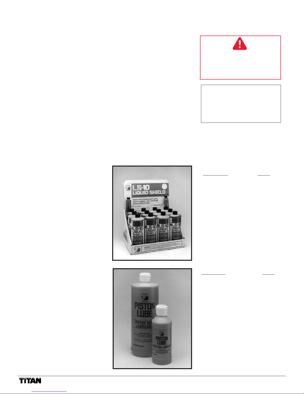
PISTON SEAL LUBRICANT
Specially formulated to prevent materi-
als from adhering to the piston rod,
which becomes abrasive to the upper
seals. Piston Lube will break down
any material that may accumulate in
the wet cup and keep it from drying.
8 oz individual........................700-925
1 qt individual.........................700-926
8 oz, case of 12 .....................700-911
1 qt, case of 12.....................700-912
AIRLESS HOSE
I.D.x Length Part #
1/4" x 50'..............................316-505
3/8" x 50'..............................690-375-50
3/16" x 3'..............................550-220
3/16" x 9'..............................550-222
3/16" x 15'............................550-221
HIGH PRESSURE SWIVELS
Pressure Rated at 5000 psi
Gun-to-Hose
1/4” NPS (F) x 1/4” NPS (M).....500-428
Hose-to-Hose
1/4” NPS (M) x 1/4” NPS(M) ....500-424
FITTINGS
Description Part #
1/4" x 1/4" Hose Coupling.........490-012
1/4" x 3/8" Hose Coupling.........490-016
3/8" x 3/8" Hose Coupling.........490-014
T-Fittings 1/4" x 1/4" .................490-036
Gun Manifold ............................500-056
Tip Filter Retainer .....................520-046
1/4" Mx1/4"F Swivel Union .......490-005
1/4" Mx3/8"F Swivel Union .......490-032
Retaining Nut Adapter ..............490-007
High Pressure Fl. Gauge ..........730-394
Parts Drawings and
Repair Information..........................15-25
Frame Assembly..............................15
Replacement Labels........................16
Engine Assembly.............................18
Maintenance ....................................19
Gear Box Assembly.........................20
Clutch Rotor & Gear Repair ............21
ON/OFF Switch................................21
Filter Block Assembly ......................22
Pressure Switch...............................23
Prime Relief Valve ...........................23
Filter Replacement...........................23
Fluid Section Assembly ...................24
Syphon Assembly............................24
Pump Repair....................................25
Equipment Job History.........................26
Specifications.......................................27
Warranty ..............................................28
Table of Contents
Accessories ............................................2
General Repairs/Service ........................3
Maintenance/Service Record .................4
Warnings ................................................5
Aviso (En Español).................................6
Attention (En Français) ..........................7
Notice: Fire or Explosion Hazards ...8–10
Start-up Procedure ...............................11
Application Techniques ........................12
Cleaning Procedure..............................13
Flushing Specifications.........................14
Airless Tip Selection.............................13
Troubleshooting..............................13–14
Airless Gun .......................................13
Spray Pattern....................................13
Airless Pump.....................................14
Accessories
LIQUID SHIELD
Cleans and protects spray systems
against rust, corrosion and premature
wear.
Case of 12 (1 quart bottles) ...700-888
1 quart ....................................700-889
WARNING: The Engine Exhaust
from this product contains chemicals
known to the State of California to
cause cancer, birth defects, or other
reproductive harm.
U.S. Patents: 3,936,002; 4,220,286;
4,457,472; 4,508,268; 4,494,697;
4,500,119; 4,626,004; 4,611,758;
4,744,571; 4,728,213; 4,768,932;
4,755,638; 4,768,929; 4,840,543;
4,908,538; 5,074,467; 5,425,506

©Titan Tool Inc. All rights reserved. 3
When transporting a unit with a gas
engine, make sure to shut the fuel off.
WARNING: Before proceeding, follow the Pressure
Relief Procedure outlined in the “Warning” section of
this manual. Additionally, follow all other warnings to
reduce the risk of an injection injury, injury from mov-
ing parts or electric shock. Always unplug the sprayer
before servicing!
CAUTION: For detailed engine maintenance and specifi-
cations, refer to the separate engine manual supplied.
Routine Maintenance:
Daily: Check and fill the gas tank. After the first 20 hours of
operation: Drain the oil and refill with clean oil.
Daily: Check the engine oil level and fill as necessary.
Weekly: Remove the cover of the air filter and clean the
element. Replace the element if necessary. If operating in
an unusually dusty environment, check the filter daily and
replace if necessary.
Replacement elements can be purchased from your local
TITAN Dealer.
Weekly: Check the level of the Piston Seal Lubricant (PSL)
in the displacement pump packing cup. Fill it if necessary.
Keeping PSL in the cup helps lubricate the packings and
piston.
After each 50 hours of operation: Change the engine oil.
Spark Plug: use only a (NKG) BP6ES plug. Gap the plug to
0.025 - 0.30 in. (0.7 -0.8 mm). Be sure to use a spark plug
wrench when installing and removing the plug.
If you have any further questions concerning your
sprayer, call TITAN:
Customer Service Department 1-800-526-5362
Fax 1-800-528-4826
Outside the U.S. Call 1-201-405-7520
Outside the U.S. Fax 1-201-405-7449
Canada 1-800-565-8665
Fax 1-905-856-8496
PowrLiner Maintenance
¤

4©Titan Tool Inc. All rights reserved.
¤
MODEL # SERIAL # DATE PURCHASED COMPANY NAME
Titan Tool is in the business of designing and manufacturing spray systems and accessories that make today’s Painting Professional
become more efficient and profitable. We feel that if you accurately track the maintenance of your equipment on this chart it will improve
the performance of this valuable tool to help you get the most out of your investment.
The chart is easy to follow and to use. The Maintenance Schedule allows for the recording of all your service work and will help you
make sure your unit is always running at peak performance.
Make sure to fill in the boxes at the top of this record with the model number, serial number, date purchased and your company name.
This information will be needed to validate your warranty.
Maintenance Schedule
Check Piston Seal Lubricant Level WEEKLY.
PowrLiner 3100
Change Engine Oil
Every 50 Hours
Date Date Date Date Date Date Date Date Date Date
Clean Air Filter Daily
It is extremely important to clean the air filter daily. Consult the Honda Engine Manual supplied with your unit for proper
cleaning instructions.
Air Filter
Replaced
Date Date Date Date Date Date Date Date Date Date
Service Record
Service Performed
Date Service Center
Cost of Repair
Months in Service
Service Performed
Date Service Center
Cost of Repair
Months in Service
Service Performed
Date Service Center
Cost of Repair
Months in Service
Service Performed
Date Service Center
Cost of Repair
Months in Service
Service Performed
Date Service Center
Cost of Repair
Months in Service
Warranty
Repair
❏ Yes
❏ No
Warranty
Repair
❏ Yes
❏ No
Warranty
Repair
❏ Yes
❏ No
Warranty
Repair
❏ Yes
❏ No
Warranty
Repair
❏ Yes
❏ No
May Be Copied For Field Use

©Titan Tool Inc. All rights reserved. 5
DO NOT USE EQUIPMENT BEFORE READING THIS SECTION
WARNING
HIGH PRESSURE SPRAY
CAN CAUSE SERIOUS INJURY
Maximum Working Pressure 3200 psi, 221 bar
An airless spray gun requires that fluid be introduced to it at very high pressure. Fluids under high pressure, from
spray or leaks, can penetrate the skin and inject substantial quantities of toxic fluid into the body. If not promptly and
properly treated, the injury can cause tissue death or gangrene and may result in serious, permanent disability or
amputation of the wounded part. Therefore, extreme caution must be exercised when using any airless spray equip-
ment. IF YOU ARE INJECTED, SEE A PHYSICIAN IMMEDIATELY. DO NOT TREAT AS A SIMPLE CUT!
NOTE TO PHYSICIAN: Injection into the skin is a serious, traumatic injury. It is important to treat the injury surgi-
cally as soon as possible. Do not delay treatment to research toxicity. Toxicity is a concern with some exotic coatings
injected directly into the bloodstream. Consultation with a plastic surgeon or a reconstructive hand surgeon may be
advised.
1) Handle the spray gun carefully. Keep clear of the nozzle. NEVER point the gun at yourself or anyone else.
NEVER permit any part of your body to come in contact with the fluid stream of either the gun or any hose
leak. ALWAYS keep the gun trigger safety lever in a locked position when not spraying. ALWAYS use a tip
safety guard.
2) NEVER attempt to force the flow of fluid backward through the gun with your finger, hand or hand-held
object against the gun nozzle. THIS IS NOT AN AIR SPRAY GUN.
3) NEVER attempt to remove tip, disassemble or repair equipment without first doing the following:
4) Before flushing system, always remove spray tip and adjust fluid pressure to lowest possible setting.
5) Tighten all fluid connections before each use. NEVER exceed 3200 psi, (221 bar) with this unit. Make sure
that all accessory hoses, connections, swivels and so forth can withstand the high pressures which develop.
NEVER exceed the pressure rating of any component in the system.
6) WARNING: The paint hose can develop leaks from wear, kinking, abuse, etc. A leak is capable of injecting
fluid into the skin, therefore the paint hose should be inspected before each use. NEVER attempt to plug a
hose with any part of your body, adhesive tape or any other makeshift device. Do not attempt to repair a
spray hose. Instead, replace it with a new grounded hose. Use only with hoses that have spring guards.
NEVER use less than 50' (7,5m) of hose with this unit.
7) Be sure that the airless equipment being used and the object being sprayed are properly grounded to pre-
vent static discharge or sparks which could cause fire or explosion. WARNING: ALWAYS hold the gun
against metal container when flushing system with tip removed, to prevent static discharge. CAUTION: To
reduce the risk of electrical shock, do not expose to rain. Store indoors.
8) ALWAYS keep the working area around the pump well ventilated. Additionally, the pump itself should be a
minimum of 25' (7,5m) from the spray area. If these instructions are not followed, there is the possibility of fire
or explosion with certain materials. ALWAYS follow the coating or solvent manufacturer's safety precautions
and warnings. Never spray flammable material near open flames, pilot lights or any source of ignition.
9) ALWAYS wear spray masks and protective eyewear while spraying. Additional personal protective equip-
ment may be required depending on the type of material being sprayed and conditions of ventilation. Always
contact supplier of material being sprayed for recommendation.
10) Keep all extension poles clear of electrical wires.
11) NEVER alter or modify any part of this equipment; doing so could cause it to malfunction.
12) NEVER leave equipment unattended. Keep away from children or anyone not familiar with the operation
of airless equipment.
PRESSURE RELEASE PROCEDURE
A. Set trigger safety in a locked position.
B. Shut off pump and unplug electrical cord.
C. Release fluid pressure from entire system and trigger gun.
¤

6©Titan Tool Inc. All rights reserved.
¤
NO USE EL EQUIPO ANTES DE LEER ESTA SECCION
ADVERTENCIA
LA ROCIADURA A PRESION ALTA
PUEDE CAUSAR LESION GRAVE.
Presión de Trabajo Máxima 3200 libras por pulgada cuadrada (psi), 221 bar
Una pistola rociadora sin aire requiere que se le introduzca líquido a presión muy alta. Los líquidos bajo presión alta, de la
rociadura o de las fugas, pueden penetrar en la piel e inyectar en el cuerpo cantidades considerables de líquido tóxico. Si no se
atiende rápida y apropiadamente, la lesión puede causar muerte del tejido o gangrena, y puede resultar en incapacidad seria y per-
manente o en la amputación de la parte lesionada. Por lo tanto, hay que emplear precauciones estrictas al usar cualquier equipo de
rociadura sin aire. SI USTED HA ESTADO EXPUESTO A LA PENETRACION DE TOXICOS POR INYECCION, CONSULTE
INMEDIATAMENTE AL MEDICO. ¡NO TRATE LA HERIDA COMO SI FUERA UNA MERA CORTADURA!
NOTA PARA EL MEDICO: La penetración de tóxicos en la piel es una herida seria y traumática. Es importante tratar la herida
quirúrgicamente lo más pronto posible. No demore el tratamiento para investigar la toxicidad. La toxicidad es asunto serio cuando se
trata de la penetración de ciertos revestimientos tóxicos en la corriente sanguínea. Puede que sea necesaria la consulta con un ciru-
jano plástico o un cirujano especialista en la reconstrucción de la mano.
1) Maneje la pistola de rociadura con cuidado. Manténgase alejado de la boquilla. JAMAS apunte la pistola hacia usted u
otra persona. NUNCA permita que parte alguna de su cuerpo se ponga en contacto con el chorro de líquido de la pistola o
de alguna fuga de la manguera. SIEMPRE mantenga trabado el seguro de la pistola mientras no esté rociando. SIEMPRE
utilice el protector de seguridad de la boquilla.
2) JAMAS intente forzar el flujo del líquido por la pistola hacia atrás con el dedo, la mano o un objeto sostenido con la
mano contra la boquilla de la pistola, ya que NO SE TRATA DE UNA PISTOLA DE ROCIADURA DE AIRE.
3) JAMAS intente quitar la boquilla ni desarmar o reparar el equipo sin haber cumplido antes con los pasos siguientes:
4) Antes de lavar el sistema, siempre quite la boquilla de rociadura y ajuste la presión del líquido al valor más bajo posible.
5) Ajuste todas las conexiones antes de cada uso. JAMAS supere 3200 (221 bar) libras por pulgada cuadrada con esta
unidad. Asegúrese de que todas las mangueras, conexiones, articulaciones giratorias y demás elementos accesorios estén
en condiciones de tolerar las altas presiones que se presentan. JAMAS exceda la clasificación de presión de cualquier
componente del sistema.
6) ADVERTENCIA: La manguera de pintura puede presentar fugas como resultado del desgaste, retorcimiento, abuso, etc.
Las fugas pueden inyectar líquido a través de la piel, por lo que la manguera de pintura debe ser inspeccionada antes de
cada uso. JAMAS intente obturar la manguera con una parte de su cuerpo o con tela adhesiva o cualquier otro elemento
improvisado. No intente reparar una manguera de rociadura; en cambio reemplácela con una manguera nueva conectada a
tierra. Utilice solamente mangueras con protector de resorte. JAMAS use una manguera de menos de 15,2 m con esta
unidad. Almacenar bajo techo.
7) Asegúrese de que el equipo sin aire que esté empleando y el objeto que se intenta rociar estén correctamente conecta-
dos a tierra para evitar descargas estáticas o chispas que podrían ocasionar incendio o explosión. ADVERTENCIA:
Sostenga SIEMPRE la pistola contra el receptáculo de metal al limpiar el sistema con la boquilla desprendida, para evitar la
descarga estática. ADVERTENCIA: Para reducir riesgo de descarga eléctrica, no exponer a la lluvia.
8) SIEMPRE mantenga el lugar de trabajo alrededor de la bomba bien ventilado. Además, la bomba en sí debe estar ubica-
da a no menos de 7,5 m de la operación de rociadura. Si no se observan estas instrucciones, existe el riesgo de incendio o
explosión con ciertos materiales. SIEMPRE observe las precauciones y advertencias de los fabricantes sobre revestimien-
tos y solventes. Nunca rocíe material inflamable cerca de llamas expuestas, llamas piloto o cualquier fuente de ignición.
9) SIEMPRE use máscaras apropiadas y anteojos de protección durante la operación de rociadura. Según el tipo de materi-
al que se está rociando y las condiciones de ventilación puede ser necesario usar equipo personal protector adicional.
Siempre comuníquese con el proveedor del material para conseguir recomendaciones.
10) Mantenga todas las varas de extensión fuera del alcance de cables eléctricos.
11) JAMAS altere o modifique parte alguna de este equipo, ya que ello puede causar deficiencias de funcionamiento.
12) JAMAS deje al equipo solo. Manténgalo fuera del alcance de los niños o de cualquier persona no familiarizada con la
operación de equipo sin aire.
PROCEDIMIENTO DE DESCOMPRESION
A. Coloque el seguro de la pistola en posición trabada.
B. Apague la bomba y desconecte también el cable de electricidad.
C. Descargue la presión del líquido de todo el sistema y de la pistola.
D. Vuelva a trabar el seguro.

©Titan Tool Inc. All rights reserved. 7
NE PAS UTILISER LE MATERIEL AVANT D’AVOIR LU CETTE SECTION
ATTENTION!
LES PULVERISATEURS A HAUTE PRESSION PEUVENT
PROVOQUER DE SERIEUSES LESIONS
Pression de travail maximale: 3200 psi — 221 bar
Le liquide introduit dans un pistolet pulvérisateur sans air doit l’être à pression extrêmement élevée. Les liquides à haute pression, en prove-
nance du pulvérisateur ou d’une fuite quelconque, sont capables de pénétrer la peau et d’injecter d’importantes quantités de liquide toxique
dans l’organisme. Si elle n’est pas traitée promptement et avec toute l’attention voulue, la lésion causée de la sorte peut provoquer la nécrose
des tissus ou la gangrène et donner lieu à de sérieux handicaps permanents, voire à l’amputation du membre atteint. Une prudence extrême
s’impose donc lors de l’utilisation de matériel de pulvérisation sans air. EN CAS D’INJECTION, CONSULTEZ UN MEDECIN IMMEDIATE-
MENT. NE TRAITEZ PAS LA BLESSURE COMME S’IL S’AGISSAIT D’UNE SIMPLE COUPURE!
REMARQUE A L’INTENTION DU MEDECIN : Une injection pénétrant la peau constitue une lésion traumatique grave qu’il est important de
traiter chirurgicalement aussitôt que possible. Ne perdez pas de temps à rechercher la toxicité de l’injection. Il s’agit là d’un risque à envisager
en cas d’injection directe dans le circuit sanguin de certains revêtements exotiques. La consultation d’un chirurgien plasticien ou d’un spécial-
iste de la chirurgie reconstructive de la main peut être conseillée.
1) Maniez le pistolet avec soin. Maintenez-vous à l’écart de la buse. N’en dirigez JAMAIS la buse vers aucune partie de votre corps
ou vers aucune autre personne. Ne laissez JAMAIS aucune partie de votre corps entrer en contact avec le flux de liquide s’échap-
pant du pistolet ou d’une fuite quelconque au niveau du flexible. Verrouillez TOUJOURS le levier de sûreté de la détente lorsque
vous n’êtes pas occupé à pulvériser. Veillez à TOUJOURS utiliser un dispositif de sûreté à la buse du pistolet.
2) N’essayez JAMAIS de refouler le flux de liquide dans le pistolet au moyen de votre doigt, de votre main ou d’un objet maintenu
contre la buse du pistolet. CET APPAREIL N’EST PAS UN PISTOLET PULVERISATEUR A AIR. N’utilisez aucune pièce de
matériel sans air avec une pompe non équipée d’une soupape de surpression.
3) N’essayez JAMAIS d’enlever la buse, de démonter ou de réparerl’appareil avant d’avoir accompli la procédure suivante :
4) Avant de procéder au rinçage du système, enlevez toujours la buse de pulvérisation et réglez la pression au niveau le plus faible
possible.
5) Serrez bien tous les raccords du système hydrodynamique avant chaque emploi. Ne dépassez JAMAIS, avec cet appareil, une
pression de 3200 psi. Assurez-vous que tous les flexibles accessoires, raccords, articulations, etc. sont bien capables de résister aux
hautes pressions prévues. Ne dépassez JAMAIS la capacité de pression nominale d’aucun composant du système. DANGER : Afin
de réduire tout risque d’électrocution, n’exposez pas à la pluie.
6) ATTENTION : Des fuites risquent de se produire le long du flexible de peinture sous l’effet de l’usure, des torsions, des rudes
traitements, etc. auxquels il est éventuellement soumis. Les injections de liquide dans la peau sont possibles par la voie de telles
fuites. Il est donc important d’inspecter le flexible avant chaque usage. N’essayez JAMAIS d’obturer une fuite à l’aide de votre doigt
ou de tout autre membre de votre corps, de ruban adhésif ou de tout autre moyen de fortune. N’essayez pas non plus de réparer un
flexible de pulvérisation ; remplacez-le plutôt par un nouveau flexible mis à la terre. Veillez à n’utiliser que les flexibles munis de dis-
positifs de sécurité à ressort. N’utilisez JAMAIS moins de 15,2 m de flexible avec cet appareil.
7) Assurez-vous que le matériel sans air utilisé et que l’objet à peindre sont adéquatement mis à la terre, de façon à éviter toute
décharge d’électricité statique ou toute étincelle susceptible de provoquer un incendie ou une explosion. ATTENTION : Tenez TOU-
JOURS le pistolet contre un récipient en métal lors du rinçage du système, après en avoir ôté la buse. Ne vaporisez JAMAIS de sub-
stances inflammables à proximité de flammes nues, lampes témoin ni d’aucune source d’allumage. Rangez à l’intérieur.
8) Le moteur électrique de cet appareil n’est pas protégé contre les explosions. Il est donc essentiel d’assurer une bonne ventilation
de la zone de travail et des alentours de la pompe. Il est également important de maintenir la pompe à une distance minimale de 7,6
m de la zone de pulvérisation. Certains matériaux présentent, à défaut de suivre ces consignes, un risque d’incendie ou d’explosion.
Suivez TOUJOURS les précautions et avertissements du fabricant de chaque solvant ou revêtement utilisé.
9) Portez TOUJOURS un masque et des lunettes de protection lors de vos travaux de pulvérisation. D’autres articles de protection
personnelle peuvent être nécessaires suivant le type de produit pulvérisé et les conditions d’aération. Demandez toujours ses recom-
mandations à votre fournisseur.
10) Maintenez toutes les tiges de rallonge à distance des fils électriques.
11) N´altérez ou ne modifiez JAMAIS une partie quelconque de cet appareil, ce qui pourrait causer des défaillances.
12) Ne laissez JAMAIS le matériel sans surveillance. Gardez-le hors de portée des enfants et de toute personne inexpérimentée
quant à l’usage de matériel sans air.
PROCEDURE DE DELESTAGE DE PRESSION
A. Verrouillez la sûreté de la détente.
B. Arrêtez la pompe et débranchez le cordon électrique.
C. Délestez la pression dans tout le système et appuyez sur la détente du pistolet.
D. Reverrouillez la sûreté de la détente.
¤

8©Titan Tool Inc. All rights reserved.
¤
FIRE OR EXPLOSION HAZARD
Static electricity is created by the high velocity of fluid through the pump, hose and tip. If every part of the spray element
is not properly grounded, sparking may occur and the system may become hazardous. Sparking may also occur when
plugging in or unplugging a power supply cord, or starting a gas engine. Sparks can ignite fumes from solvents or the
fluids being sprayed. Always plug the sprayer into an outlet at least 25' (7,5) away from the spray area.
WARNING: Always flush the unit into a separate metal container with the spray tip removed and the gun held
firmly against the side of the container to assure proper grounding and prevent static discharge which could
cause serious bodily injury.
If you experience any static sparking or slight shock while using this equipment, stop spraying immediately. Check the
entire system for proper grounding. Do not use the system again until the problem has been corrected.
ELECTRIC MOTOR
The electric motors used by TITAN are not explosion proof. Therefore, it is essential to keep the working area
around the pump well ventilated. Additionally, the pump itself should be a minimum of 25' (7,5) from the spray
area.
WARNING: Always keep pump outside of any enclosed spray area. Never clean the exterior of the pump with
any flammable solvents.
GAS ENGINE (Where Applicable)
Always keep pump outside of any enclosed spray area. Keep area around pump well ventilated. Keep all sol-
vents away from engine exhaust. (Never fill the fuel tank while the engine is running or hot. Fuel spilled on a
hot surface can ignite and cause a fire.) Always attach ground wire located on rear of engine to a grounded
object, i.e. water pipe. NOTE: Refer to engine owner's manual for additional safety and service information.
FLUID SECTION—SOLVENTS
Halogenated Hydrocarbon solvents can cause an explosion when used with aluminum or galvanized components in a
closed (pressurizable ) fluid system (pumps, heaters, filters, valves, spray guns, tanks, etc.). The explosion could cause
serious injury, death and/or substantial property damage. Cleaning agents, coatings, paints, etc. may contain
Halogenated Hydrocarbon solvents. Titan Tool Inc. spray equipment includes aluminum or galvanized components
and will be affected by Halogenated Hydrocarbon solvents. DO NOT USE HALOGENATED HYDROCARBONS IN THE
PowrLiner 3100.
EXPLANATION OF THE HAZARD
There are three key elements to the Halogenated Hydrocarbon (HHC) solvent hazard. These elements are:
1. The presence of HHC solvents.
2. Aluminum or galvanized parts.
3. Equipment capable of withstanding pressure.
When all three elements are present, the result can be an extremely violent explosion. The reaction can be sustained
with very little aluminum or galvanized metal: any amount of aluminum is too much. The reaction is unpredictable.
Prior use of an HHC solvent without incident (corrosion or explosion) does NOT mean that such use is safe.
PELIGRO DE INCENDIO O EXPLOSIÓN
La alta velocidad del líquido a través de la bomba, manguera y la boquilla produce electricidad estática. Si algún com-
ponente del equipo de rociadura no está conectado a tierra correctamente pueden producirse chispas y el sistema se
vuelve peligroso. También pueden producirse chispas al enchufar o desenchufar cables eléctricos o al poner en fun-
cionamiento un motor a gasolina. Las chispas pueden encender los vapores provenientes de los solventes o de los
líquidos rociados. Siempre conecte el rociador a un enchufe ubicado a no menos de 7,5m de distancia de la zona de
rociadura.
ADVERTENCIA: Lavar siempre la unidad en un recipiente metálico separado, habiendo quitado la boca del roci-
ador y teniendo la pistola firmemente contra el lado del recipiente para asegurar una puesta a tierra correcta y
evitar la descarga estática que podría causar lesión corporal grave.
Si ocurren chispas de electricidad estática o si sufre un shock eléctrico ligero mientras usa el equipo, deje de rociar de
immediato. Verifique que el sistema en su totalidad esté conectado a tierra correctamente. No vuelva a usar el sistema
hasta que el problema haya sido resuelto.
MOTOR ELÉCTRICO:
Los motores eléctricos utilizados por TITAN no son a prueba de explosión. Por lo tanto, es esencial mantener
el área de trabajo alrededor de la bomba bien ventilada. Además, la bomba misma debe estar a una distancia
minima de 7,5m del area de rociadura.
ADVERTENCIA: Mantener siempre la bomba afuera de cualquier área de rociadura cerrada. Nunca limpie el
exterior de la bomba con solventes inflamables.

©Titan Tool Inc. All rights reserved. 9
MOTOR A GASOLINA: (Si fuera aplicable)
Siempre mantenga la bomba afuera de cualquier zona de rociadura cerrada. Mantenga el área alrededor de la
bomba bien ventilada. Mantenga todos los solventes lejos del escape del motor. (Nunca liene el tanque de
combustible cuando el motor esté funcionando o caliente. El combustible derramado sobre una superficie
caliente puede encenderse y producir un incendio). El cable a tierra que está ubicado en la parte de atrás del
motor debe estar siempre adherido a un objeto conectado a tierra, por ejemplo, una cañería de agua. NOTA:
Vea el manual de uso del motor para información adicional sobre seguridad y mantenimiento.
SECCION FLUIDO—SOLVENTES
Los solventes a base de hidrocarburos halogenados pueden provocar explosión cuando se usan con componentes gal-
vanizados o de aluminio en un sistema líquido cerrado (sujeto a presión) (bombas, calefactores, filtros, válvulas, pistolas
de rociadura, tanques, etc.) La explosión podría causar lesiones serias e inclusive la muerte, así como daños materi-
ales de consideración. Los líquidos de limpieza, revestimientos, pinturas, etc. pueden contener solventes a base de
hidrocarburos halogenados. El equipo de rociadura ofrecido por Titan Tool Inc. tiene componentes galvanizados o de
aluminio y será afectado por solventes a base de hidrocarburos halogenados. NO USE HIDROCARBUROS HALOGE-
NADOS EN EL EQUIPO PowrLiner 3100.
EXPLICACION DEL RIESGO
Hay tres elementos fundamentales que condicionan el riesgo de los hidrocarburos halogenados, a saber:
1. Presencia de solventes de hidrocarburos halogenados.
2. Componentes galvanizados o de aluminio.
3. Equipo capaz de tolerar presión.
Cuando todos estos elementos están presentes, el resultado puede ser una explosión sumamente violenta. La reacción
puede tener lugar aun cuando la cantidad de aluminio o metal galvanizado sea muy pequeña: cualquier cantidad de alu-
minio es excesiva. La reacción no puede predecirse. El hecho de que un solvente a base de hidrocarburos halogena-
dos haya sido usado anteriormente sin accidentes (corrosión o explosión) NO significa que dicho uso no es peligroso.
DANGER!
RISQUE D'INCENDIE OU D'EXPLOSION
La vitesse du liquide à travers la pompe le flexible et la buse produit de l'électricité statique. Si tous les éléments du
matériel de pulvérisation ne sont pas mis à la terre de manière adéquate, ils risquent de favoriser la production d'étincelles
et de rendre le système dangereux. Des étincelles peuvent également se produire lors de branchement ou débranchement
d'un cordon d’alimentation électrique ou lors de la mise en marche d'un moteur au gaz. De telles étincelles sont suscepti-
bles d'enflammer les vapeurs des solvants ou les liquides pulvérisés. Veillez donc toujours à brancher le pulvérisateur
dans une prise située à au moins 7,5m du pulvérisateur et de la zone de travail.
MISE EN GARDE: Toujours rincer l’appareil dans un récipient métallique distinct après avoir enlevé le bec de pul-
vérisation et en tenant fermement le pistolet contre le côté du récipient afin d’assurer une mise à la terre appro-
priée et de prévenir une décharge statique susceptible de causer des blessures graves.
Si vous remarquez la formation d'étincelles sous l'effet de la présence d'électricité statique ou que vous ressentez une
légère décharge électrique en cours d'utilisation du matériel, arrêtez immédiatement la pulvérisation. Assurez-vous que
tous les éléments du système sont bien mis à la terre. Ne remettez pas le système en marche avant d'avoir résolu le prob-
lème.
MOTEUR ÉLECTRIQUE
Les moteurs électriques utilisés par TITAN ne sont pas protégés contre les explosions. Il est donc essentiel d'as-
surer une bonne ventilation de la zone de travail et des environs de la pompe. Il est également important de main-
tenir la pompe à une distance minimale de 7,5m de la zone de pulvérisation.
ATTENTION: N'introduisez jamais la pompe dans une zone de pulvérisation fermée. Ne nettoyez jamais nettoyer
l'extérieur de la pompe à l'aide de solvants inflammables.
MOTEUR AU GAZ (le cas échéant)
N'introduisez jamais la pompe dans une zone de pulvérisation fermée. Veillez à ce que les environs de la pompe
soient toujours bien aérés. Ne placez aucun solvant à proximité du système d'échappement du moteur. (Ne rem-
plissez jamais le réservoir à carburant lorsque le moteur tourne ou s'il est chaud. Renversé sur une surface
chaude, le gaz pourrait s'enflammer et provoquer un incendie.) Veillez à toujours bien raccorder le fil de terre
situé à l'arrière du moteur à un objet mis à la terre (par exemple, une conduite d'eau). REMARQUE: Pour plus de
détails sur les mesures de sécurité et d'entretien pertinentes, consultez le manuel fourni avec le moteur.
SECTION HYDRODYNAMIQUE—SOLVANTS
Les solvants à hydrocarbure halogéné sont explosifs en présence de pièces galvanisées ou en aluminium dans un sys-
tème hydrodynamique fermé (pressurisable) (pompes, radiateurs, filtres, soupapes, pistolets pulvérisateurs, réservoirs, etc.)
L'explosion provoquée pourrait donner lieu à des lésions corporelles graves ou même mortelles et/ou à de sérieux dégâts
matériels. Certains produits d'entretien, revêtements, peintures et autres liquides contiennent des solvants à hydrocarbure
halogéné. Les appareils pulvérisateurs de la Titan Tool Inc. comportent des pièces en aluminium et des composants gal-
vanisés sensibles aux solvants à hydrocarbure halogéné. N’EMPLOYER PAS D’HYDROCARBURES HALOGÉNÉS
DANS LE MATÉRIEL PowrLiner 3100.
¤

10 © Titan Tool Inc. All rights reserved.
¤
EXPLICATION DU RISQUE
Le danger que présentent les solvants à hydrocarbure halogéné se caractérise par trois éléments clés:
1. La présence de solvants à hydrocarbure halogéné
2. La présence de pièces en aluminium ou galvanisées
3. Un matériel capable de supporter des pressions élevées
La combinaison de ces trois éléments peut donner lieu à une explosion extrêmement violente. La réaction peut se produire
en présence d'une quantité minime d'aluminium ou de métal galvanisé. En fait, la moindre trace d'aluminium en constitue
déjà trop.
La réaction est imprévisible. Toute utilisation antérieure de solvant à hydrocarbure halogéné n'ayant donné lieu à
aucun incident (corrosion ou explosion) NE CONSTITUE NULLEMENT un signe de sécurité.
HALOGENATED SOLVENTS
DEFINITION -- Any hydrocarbon solvent containing any of the elements as listed below:
Consult your material supplier to determine whether your solvent or coating contains Halogenated Hydrocarbon Solvents.
SOLVENTES HALOGENADOS
DEFINICION -- Cualquier solvente a base de hidrocarburos que contenga cualquiera de estos elementos:
EJEMPLOS (lista parcial):
Consulte la información suministrada por su proveedor de materiales para determinar si un solvente o revestimiento
contiene solventes de Hidrocarburos Halogenados.
SOLVANTS HALOGÉNÉS
DÉFINITION -- Tout solvant à hydrocarbure contenant l'un des éléments suivants:
EXEMPLES (liste incomplete):
Pour déterminer si vos solvants ou revêtements contiennent des solvants a hydrocarbure halogéné, consultez votre
fournisseur.
Fluorine (F) "-fluor-" Chlorine (CI) "-chloro-"
Bromine (Br) "-bromo-" Iodine (I) "-Iodo-"
EXAMPLES
(not all-inclusive):
FLUOROCARBON SOLVENTS:
Dichlorofluoromethane
Trichlorofluoromethane
BROMINATED SOLVENTS:
Ethylene dibromide
Methylene chlorobromide
Methyl bromine
IODINATED SOLVENTS:
N-butyl iodide
Methyl iodide
Ethyl iodide
Propyl iodide
CHLORINATED SOLVENTS:
Carbon tetrachloride
Chloroform
Ethylene dichloride
METHYLENE CHLORIDE or
DICHLOROMOETHANE
Monochlorobenzene
Orthodichlorobenzene
Perchloroethylene
TRICHLOROETHANE
Trichloroethylene
Monochlorotoluene

©Titan Tool Inc. All rights reserved. 11
Startup Procedure
WARNING: High pressure device, thoroughly read and understand the warning section located in the owner's manual and
the label on the sprayer.
IMPORTANT: Whenever starting or cleaning this sprayer, always reduce engine or motor speed. Additionally, never operate
this sprayer for more than 10 seconds without fluid, this can cause unnecessary wear to the packings.
Do not operate dry.
Step 1: Before you plug in the power cord to the electrical outlet or start the gas engine, do the following:
A. Tighten suction and return hoses, then install a minimum of 50' (15,2 m) of nylon airless spray hose and airless
gun. Do not install tip yet, or remove if installed.
WARNING: If you are supplying your own hoses and spray gun, be sure they are electrically grounded and rated for at least
3200 psi (221 bar) working pressure, and that the gun has a tip guard. This is to reduce the risk of serious bodily injury
caused by static sparking and fluid injection or over-pressurization, causing a component rupture.
B. Preset pressure control by turning the pressure control knob counterclockwise to lowest setting.
C. Place on-off switch in the off position.
D. Be sure to fill the Wet Cup 1/3 full with Piston Seal Lubricant.
Step 2: GAS ENGINE
A. Check the engine oil level. For instructions refer to the engine manual
supplied.
B. Fill the gas tank. Be sure the engine is cool. Refueling a hot engine
could cause a fire. Close the black fuel shut off lever located under the
air cleaner. Use unleaded high quality gasoline.
C. If a secondary hose and gun is not installed, be sure the plug is secure.
D. Place the suction tube into container containing mineral spirits.
E. Open the fuel shut off lever by pushing it in the direction of the arrow.
F. Move the throttle lever away from fuel tank.
G. Close the engine choke lever, located beneath the air cleaner.
H. Turn the engine switch on. Turn pressure relief prime valve down to
prime position.
I. Pull the starter rope. Holding the frame with one hand, pull the rope
rapidly and firmly. Continue to hold the rope as you let it return. Pull
and return rope until engine starts.
Step 3: Flush oil out of new paint pump: Oil is used by the factory for testing and protection. It is necessary to flush out with
mineral spirits before you begin to spray.
A. Pour 1/2 gallon mineral spirits into a metal container and insert syphon and return tube.
B. Turn pressure relief prime valve down to prime position and turn unit on. Increase pressure slightly. Let solvent
cycle for approximately 30 seconds. Then tilt syphon tube above container and let the sprayer pump itself dry.
Then turn unit off. If you are going to use water based paints, repeat procedure using water.
Step 4: Prepare the paint according to manufacturer's recommendations. Remove any skin that may have formed and stir.
Strain the paint through a fine nylon mesh bag to remove particles that could clog spray tip.
Step 5: Place syphon and return tubes into paint container. Turn pressure relief priming knob, located on side of pump,
down for priming.
Step 6: Turn sprayer on and turn up pressure slightly. Let circulate on prime until no bubbles filter up through the paint.
Step 7: Hold gun firmly against a metal container, disengage trigger lock and trigger gun against side of container. Then,
while gun is triggered, turn the pressure relief valve to the spray position. Keep the gun triggered until all the air is
forced out of the system and the paint flows freely. Release the trigger and engage gun safety lock; set gun down
while unit pressurizes.
Step 8: Check for leaks. If any leaks occur, follow the proper pressure relief procedure before tightening.
Step 9: Turn off sprayer and relieve pressure by turning pressure relief prime knob to prime.
Step 10: With gun trigger lock engaged, install tip and guard as instructed in separate tip or gun manual.
Step 11: Turn sprayer on and rotate the pressure relief prime valve to the spray position.
Step 12: Test on cardboard to check spray pattern. Adjust pressure just until the spray from gun is completely atomized.
¤

12 © Titan Tool Inc. All rights reserved.
¤
Application Techniques
WARNING: Before changing gun position or
adjusting gun angle, follow pres-
sure relief procedure outlined on
page 5 of this manual.
The spray tip should be a distance of 6” from the sur-
face to maintain correct spray pattern.
The spray tip is in the shape of an arrow. It should
always point at your work. If you are spraying a curb,
aim spray tip at the top corner of the curb.
1) Always spray with water rather than paint to confirm
gun position.
2) Adjust pressure to achieve proper atomization. Using
too much pressure will result in excessive overspray.
3) Always be sure that the Powrliner 3100 is in motion
before triggering and releasing the gun. This will apply
at cleaner more uniform line.
4) Always check gun position on paper or cardboard
before proceeding.
5) When applying parking lot lines, position the spray tip
so it is beyond the front end of frame. This will allow the
line to end at the curb.
6) Applying markings or lines that do not meet a curb,
adjust gun so it is parallel with front caster. This will
lessen the effects of bumps on spray pattern.
7) To adjust gun position loosen clamps A and C; this
will allow the gun to move up, down, forward or back
and out and in.
8) Should hose be removed for general painting or
stenciling, make sure when winding hose back up on
brackets, not to make the coil too tight. A tight coil will
transmit pump vibration to spray gun. This effect will
result in a wavy pattern.
9) When returning gun to gun mount assembly, make
sure that gun is as far forward as possible before tight-
ening knob B.

©Titan Tool Inc. All rights reserved. 13
Cleaning Procedure
WARNING: High pressure device --
Follow all safety warnings located on
sprayer and in the owner's manual.
Always clean using low pressure,
with the spray tip removed. Always
flush into a separate metal container
away from the sprayer. Never clean
the exterior of the pump while the
pump is plugged in or operating.
PRESSURE RELEASE PROCEDURE:
Step 1: Engage trigger safety lock on
gun.
Step 2: Turn off pump and release fluid
pressure by turning the pressure relief
prime valve located on the side of pump
down.
LOW PRESSURE CLEANING PRO-
CEDURE:
Step 3: Remove tip and let soak clean,
in a small container of solvents or
water. Adjust fluid pressure to lowest
possible setting.
Step 4: Turn the pump on. Tilt syphon
tube above paint container, allowing the
sprayer to pump itself dry through the
return tube.
Step 5: Have available container of hot
soapy water if spraying latex (or suit-
able solvent for oil base paints). Do not
clean with mineral spirits if using latex
paint as this will make jelly.
Step 6: Place syphon tube into contain-
er with hot soapy water or solvents. Let
circulate for 2-3 minutes, then turn unit
off.
Step 7: To save paint still in spray
hose, turn prime valve up to spray posi-
tion, then carefully trigger gun into and
against side of metal paint container.
Be careful of splashing. When cleaning
solution appears, shut off gun and place
gun in a separate metal container.
Repeat process if spraying with two
guns.
Step 8: Trigger gun and let cleaning
solution circulate for approximately 2-3
minutes, then turn unit off.
Step 9: Turn prime valve down and
remove suction tube from cleaning con-
tainer. Turn unit on and allow sprayer to
pump dry.
Step 10: Take a clean container of
water or solvent and using low pressure
pump through system until clear. If
cleaning with water, pump a small
amount of mineral spirits or TITAN LS-
10 solution through pump. This will
protect against corrosion.
Step 11: Take suction tube out of con-
tainer and let sprayer run itself dry.
Step 12: Check filter on pump and gun.
Clean or replace.
Step 13: Remove spray tip from sol-
vent, clean with a soft bristle brush and
store in a dry place.
PROBABLE CAUSE
1. Inadequate fluid delivery
2. Fluid not atomizing
3. Insufficient velocity
4. Material too cohesive
5. Tip worn past pump capacity
1. Worn tip
2. Tip may be chipped
1. Plugged, worn or chipped tip
1. Leak in suction tube
2. Not enough hose
3. Tip too large or worn
PROBLEM
Tails
Heavy centered pattern
Distorted pattern
Pattern expanding and
contracting (Surge)
REMEDY
1. Increase pressure
2. Change to smaller tip
3. Clean gun & pump filters
4. Reduce viscosity
5. Replace
1. Replace
2. Replace
1. Clean or replace
1. Tighten
2. Use a minimum of 50'
(15m) of 1/4" high
pressure hose
3. Replace with a new or
smaller tip
TROUBLESHOOTING SPRAY PATTERNS
REMEDY
1. Inspect connections for
air leaks
2. Disassemble and clean
3. Inspect and adjust
4. Inspect and replace
1. Replace
2. Adjust
3. Clean
1. Check fluid supply
2. Clean
3. Replace
PROBABLE CAUSE
1. Air in system
2. Dirty gun
3. Needle assembly out of adjustment
4. Broken or chipped seat
1. Worn or broken needle & seat
2. Needle assembly out of adjustment
3. Dirty gun
1. No paint
2. Plugged filter or tip
3. Broken needle in gun
PROBLEM
Spitting gun
Gun will not shut off
Gun does not spray
TROUBLESHOOTING AIRLESS GUN
Tips are selected by the orifice size and fan width at 6” from the sur-
face. (1704 is .017 orifice and a 4” wide pattern.)
Recommendations:
Application Tip
Parking Lot Lines . . . . . . . . . . . . . . . . . . . . . .645-1704*
Side Marks Long . . . . . . . . . . . . . . . . . . . . . .645-2304
Athletic Lines . . . . . . . . . . . . . . . . . . . . . . . . .645-1502
Crosswalks . . . . . . . . . . . . . . . . . . . . . . . . . .645-1910
Stencilling . . . . . . . . . . . . . . . . . . . . . . . . . .641-317
Curbs . . . . . . . . . . . . . . . . . . . . . . . . . .645-1706
General Painting . . . . . . . . . . . . . . . . . . . . . . .641-517*
* Packaged with unit.
AIRLESS TIP SELECTION
¤

14 © Titan Tool Inc. All rights reserved.
¤
Flushing
Specifications
1. New Sprayer: Oil is used by the
factory for testing and protection. It
is necessary to flush unit before
spraying.
A. If spraying water-base paint, flush
with mineral spirits followed by
water.
B. If spraying oil-base paint, flush
with mineral spirits only.
2. Changing from water-base to
oil base: Flush with water, then
mineral spirits.
3. Changing from oil-base to
water-base: Flush with mineral spir-
its, then water.
4. Changing colors: Flush with a
compatible solvent such as water or
mineral spirits.
5. Storage: To assure proper per-
formance and long life, always clean
the sprayer thoroughly before stor-
ing.
A. Water-Base Paint: Flush with
water, then mineral spirits and leave
the pump, gun and hose filled with
mineral spirits. Shut off and unplug
the sprayer and turn pressure relief
prime valve to prime to relieve pres-
sure. Return prime valve to spray
position.
B. Oil-Base Paint: Flush with min-
eral spirits. Shut off and unplug the
sprayer, turn the pressure relief
prime valve to prime to relieve pres-
sure and leave open. Return prime
valve to spray position.
• During storage the power cord
must be coiled around cord holder
to avoid damage.
6. Start-Up After Storage:
A. Water-Base Paint: Flush out
mineral spirits with water.
B. Oil-Base Paint: Flush out the
mineral spirits with the material to be
sprayed.
Always dispose of mineral spirits in
a proper way.
PROBLEM
Electric motor won't run
Gas engine won't start
Pump won’t prime
Insufficient material flow
Pump will not maintain
pressure
Not enough pressure
Excessive surge at
spray gun
Paint leaks into oil cup
PROBABLE CAUSE
1. Unit unplugged or circuit fuse
blown
2. Pressure setting too low
3. Brushes on motor are worn
4. Electric motor burned out
5. Switch defective
6. Fuse in pump blown
1. Engine switch not on
2. Engine oil level low
3. Out of gas
4. Spark plug cable disconnect-
ed or bad plug
1. Air leak in syphon hose.
2. Insufficient pressure
3. Clutch worn or damaged
(Gas models)
1. No paint
2. Syphon strainer clogged
3. Pump/gun filter clogged
4. Pump will not prime, material
too heavy
5. Engine not tuned properly
(Gas)
6. Worn clutch (Gas models)
1. Air leak in system
2. Air leak in syphon tube
3. Inlet valve not seating
4. Worn packings
5. Dirty or worn ball valves
6. Worn valve seats
7. Worn prime valve
1. Pressure setting too low
2. Plugged filters
3. Spray tip too big or worn
4. Engine or motor rpm too low
(Gas)
1. Wrong type of hose
2. Spray tip too big or worn
3. Excessive pressure
1. Worn out packings
REMEDY
1. Check
2. Increase
3. Replace
4. Replace
5. Replace
6. Replace
1. Turn on
2. Try starting engine. If light
on rear glows, add oil
3. Fill
4. Connect or replace
1. Check syphon tube O-
Ring and/or let paint cir-
culate in prime position
2. Increase pressure
3. Replace
1. Check supply
2. Clean
3. Clean & replace
4. Thin material
5. Tune engine
6. Service
1. Tighten connections
2. Tighten, check for leaks
3. Service or clean
4. Replace
5. Clean or replace
6. Reverse
7. Replace
1. Increase
2. Clean or replace
3. Change or replace
4. Increase throttle
1. Replace with a minimum
50' grounded nylon braid
high pressure hose
2. Change or replace
3. Decrease pressure and
engine speed
1. Replace
TROUBLESHOOTING AIRLESS PUMP

©Titan Tool Inc. All rights reserved. 15
1
2
3
4
5
6
7
8
9
10
11
12
13
14
16
17
18
19
20
21
22
23
24
26
25
27
15
28
29
30
31
10
32
11
35
42
43
44
45
46
47
64
63
59
60
61
37
10
62
65
68
66
67
48
49
50
51
52
53
54
55
56
57
58
36
37
39
41
40
33
34
38
Frame Assembly
Item Part # Description Quantity
1 757-092 Screw ......................................................4
2 759-035 Strap........................................................2
3424-245 Grip, Handle ............................................2
4 756-136 Lever .......................................................2
5 226-001 Nut...........................................................4
6759-008 Cable, Caster Lock..................................1
7424-247 Cable Clip................................................4
8759-020 Handle.....................................................1
9 756-154 Screw ......................................................6
10 862-001 Washer .................................................16
11 862-410 Nut.........................................................14
12 756-067 12" Wheel/Tire.........................................2
13 756-079 Cotter Pin ................................................2
14 756-078 Nut...........................................................2
15 756-080 Spring Washer ........................................2
16 710-058 Axle Washer............................................2
17 756-056 Plug .........................................................2
18 756-029 Block, Slide .............................................1
19 761-405 Ring, Snap ..............................................2
20 424-226 Clamp, Cable ..........................................1
21 756-045 Bracket, Sliding .......................................1
22 424-224 Arm, Support ...........................................1
23 424-201 Holder, Gun.............................................1
24 756-035 Clamp......................................................1
25 858-912 Screw, Shoulder......................................1
26 858-636 Screw ......................................................2
27 858-002 Washer, Lock ..........................................2
28 759-011 Cable, Trigger Pull ..................................1
Item Part # Description Quantity
29 770-413 Screw, Self Tapping................................2
30 770-737 Ground wire.............................................1
31 756-062 Plate, Engine...........................................1
32 862-468 Screw ......................................................2
33 757-042 Mount, Vibration ......................................3
34 756-122 Grommet .................................................3
35 759-005 Axle Weldment ........................................1
36 756-130 Clamp......................................................2
37 862-002 Washer....................................................3
38 757-022 Rod, Clamp .............................................2
39 759-110 Screw ......................................................2
40 862-436 Screw ......................................................1
41 756-087 Spring......................................................1
42 759-013 Block, Guide............................................1
43 759-012 Pin, Caster Lock......................................1
44 759-014 Cover, Block............................................1
45 700-784 Screw ......................................................4
46 759-016 Screw ......................................................1
47 759-057 Spring holder (long).................................1
48 858-637 Screw ......................................................1
49 759-058 Spring......................................................1
50 759-056 Spring holder (short) ...............................1
51 424-202 Lever .......................................................1
52 860-936 Screw, Shoulder......................................1
53 424-248 Brg. Flange..............................................2
54 858-603 Nut...........................................................1
55 424-249 Brg. Sleeve..............................................1
56 858-653 Screw ......................................................1
57 858-601 Nut...........................................................1
58 424-229 Fitting, Grease.........................................2
59 756-034 Knob, Clamp ...........................................2
60 756-157 Screw ......................................................4
61 756-154 Screw ......................................................2
62 759-004 Frame, Base............................................1
63 313-1245 Label Powrliner 3100 ..............................1
64 313-174 Label Warning .........................................1
65 424-281 Caster (includes item 67) ........................1
66 866-004 Washer....................................................4
67 866-210 Nut...........................................................4
68 424-280 Wheel (only) ............................................1
¤

PowrLiner 3100 Assembly
16 © Titan Tool Inc. All rights reserved.
¤
WARNING: Before proceeding, follow the Pressure Relief
Procedure found previously in this manual. Additionally,
follow all other warnings to reduce the risk of an injection
injury, injury from moving parts or electric shock. Always
unplug the sprayer before servicing!
When transporting a unit with a gas engine, make sure to
shut fuel off.
Figure 5
Replacement Labels
Part # Description Quantity
759-040 Front Plate (front cover label)......................1
313-1245 PowrLiner 3100............................................1
313-191 Warning Label (in English) ..........................1
313-201 Warning/Attention Label (in French)...........1

©Titan Tool Inc. All rights reserved. 17 ¤

18 © Titan Tool Inc. All rights reserved.
¤
1
7
8
9
10
2
3
4
5
6
11
12
14
15
13
Item Part # Description Quantity
1 750-042 Gasket .............................................1
2750-086 Engine Mount (includes items 3 & 4).1
3750-044 Engine Bearing ................................1
4750-043 Engine Seal .....................................1
5700-722 Terminal ..........................................1
6 730-158 Dipstick ............................................1
7750-051 Screw...............................................6
8755-209 Clutch Plate ....................................1
9763-550 Bushing (Incl. #74)...........................1
10 763-566 Screw...............................................2
11 700-652 Screw...............................................6
12 755-117 Engine Assembly
(includes items 1-7, 11, & 14)..........1
13 750-018 Screw...............................................2
14 730-184 Electrical Connector.........................1
15 755-150 Clutch Plate & Bushing....................1
Figure 6
Engine Assembly

©Titan Tool Inc. All rights reserved. 19
WARNING: When transporting a unit with a gas engine,
make sure to shut the fuel off.
The Powrliner 3100 contains a clutch that engages when the
unit is pumping. The pump’s pressure control device engages
and disengages the clutch to control pressure. To prevent
unnecessary wear to the clutch, it is advisable to adjust your
engine speed and pressure setting so as to limit the amount of
times the clutch engages and disengages. This can be accom-
plished as follows:
Example
Operating one gun with .019 tip: To reduce clutch wear,
reduce engine speed by adjusting the throttle to a low or medi-
um setting and increase pressure only until heavy ends of spray
pattern have been eliminated.
Example
Operating one gun with .023 tip: Increase engine speed to a
high setting and increase pressure until heavy ends of spray
pattern have been eliminated.
Example
Spraying light-bodied materials at low pressure. To reduce
surging at the gun and to decrease clutch wear, reduce engine
speed to idle and reduce pressure until desired spray pattern is
achieved.
Important Facts Concerning Your PowrLiner 3100
WARNING: Before proceeding, follow the Pressure Relief
Procedure outlined on Page 5. Additionally, follow all other
warnings to reduce the risk of an injection injury, injury
from moving parts or electric shock. Always unplug the
sprayer before servicing!
Caution: For detailed engine maintenance and specifica-
tions, refer to the separate engine manual supplied.
Routine Maintenance
Daily: Check and fill the gas tank. After the first 20 hours of
operation: Drain the oil and refill with clean oil.
Daily: Check the engine oil level and fill as necessary.
Weekly: Remove the cover of the air filter and clean the ele-
ment. Replace the element if necessary. If operating in an
unusually dusty environment, check the filter daily and replace if
necessary.
Replacement elements can be purchased from your local TITAN
Dealer.
Weekly: Check the level of the Piston Seal Lubricant (PSL) in
the displacement pump packing cup. Fill it if necessary.
Keeping PSL in the cup helps lubricate the packings and piston.
After each 50 hours of operation: Change the engine oil.
Spark Plug: use only a (NKG) BP6ES plug. Gap the plug to
0.025 - 0.030 in. (0.7 - 0.8 mm). Be sure to use a spark plug
wrench when installing and removing the plug.
Maintenance
WARNING: Before proceeding, follow the Pressure Relief
Procedure outlined on Page 5. Additionally, follow all other
warnings to reduce the risk of an injection injury, injury
from moving parts or electric shock. Always unplug the
sprayer before servicing!
1. Remove (4) screws #54 located on page 20.
2. Inspect clutch plate #8 for wear.
3. If worn, remove 2 screws #10 and pull clutch from engine
shaft.
4. To reinstall new clutch, slide clutch plate assembly #8 on
engine shaft.
5. Install clutch gap tool 755-221 behind clutch plate and push
clutch against tool till tool touches the engine mount #2.
6. Tighten screws #10.
7. Reassemble engine assembly #12 with allen screws #54 on
page 20.
NOTE: All service work on the Engine must be done
by a Honda Authorized Service Center. To
locate one in your area call Titan Customer
Service at 1-800-526-5362.
Service / Replacement of Clutch Assembly
¤

20 © Titan Tool Inc. All rights reserved.
¤
Item Part # Description Quantity
19 763-551 Washer ............................................3
20 755-218 Screws .............................................3
21 755-203 Clutch Rotor.....................................1
22 755-216 Coil...................................................1
25 755-201 Drive Shaft & Pinion ........................1
26 700-771 Adjustment Knob .............................1
27 700-784 Screw...............................................2
28 763-525 Screw...............................................4
29 730-390 Connector ........................................1
30 730-151 Connector ........................................1
32 700-811 O-Ring .............................................1
40 730-260 Screw.............................................11
41 759-040 Cover .............................................. 1
42 700-681 Screw.............................................. 4
43 750-008 Pump HSG Ass’y............................ 1
44 700-680 Thrust Washer ............................... 1
45 730-360 Crank Shaft..................................... 1
46 730-088 Thrust Washer ................................ 1
47 700-688 Thrust Washer ................................ 1
48 730-167 Output Pinion Ass’y ........................ 1
Gear Box Assembly
Item Part # Description Quantity
49 700-514 Thrust Washer .................................1
50 730-144 Snap Ring ........................................1
51 750-016 Snap Ring ........................................1
52 750-015 Ball Bearing .....................................1
53 755-211 Gear Box HSG Ass’y .......................1
54 730-148 Screw...............................................4
56 710-127 Set Screw ........................................1
57 730-145 Screw...............................................2
58 763-557 Clutch Starter...................................1
59 730-146 5 AMP Fuse.....................................1
60 761-132 Switch Cover Plate ..........................1
61 765-072 Switch to Starter .............................1
Wire
62 700-646 On/Off Switch...................................1
63 700-775 On /Off Plate....................................1
64 700-645 Rubber Boot.....................................1
66 761-192 Insulator Plate..................................1
70 700-791 Safety Plate .....................................1
72 730-172 Clutch Seal ......................................1
Figure 7
Table of contents
Other Titan Pressure Washer manuals

Titan
Titan Performance 650e Series User manual

Titan
Titan TTB669PRW User manual

Titan
Titan TTM2700PRW User manual

Titan
Titan TTB2700PRW User manual

Titan
Titan 1800M User manual

Titan
Titan TTI855PRW User manual

Titan
Titan TTB2200PRW-DSS User manual

Titan
Titan Compact 190 User manual

Titan
Titan TPW-2200 User manual

Titan
Titan PowrTwin Plus 0290032 User manual
Popular Pressure Washer manuals by other brands

North Star
North Star M157305G Installation, operation and maintenance manual

Ryobi
Ryobi HydroSurge RPW130HS Operator's manual

Kärcher
Kärcher G 2600 OR Operator's manual

Kärcher
Kärcher AP 50 M instruction manual

Bosch
Bosch AQT 42-13 Original instructions

Parkside
Parkside PHD 150 B2 translation of original operation manual